The figures show the installation of a steel HB profile rail of size HB150S. The installation of larger or smaller HB profile rails or aluminium HB profile rails does not differ significantly from this.
|
|
The figures show the installation of a steel HB profile rail of size HB150S. The installation of larger or smaller HB profile rails or aluminium HB profile rails does not differ significantly from this. |
|
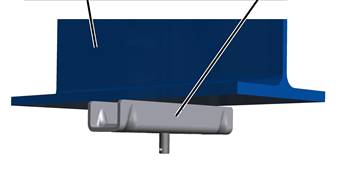
Supporting structure |
Ceiling-mounted bracket 2LP/M16 or M20 |
|
| |
─ First, all 2LP/M16 or M20 ceiling-mounted brackets are assembled on the supporting structure.
There are eight different versions for assembling the ceiling-mounted brackets. The supporting structure will determine which version is used:
o With flange clamp on I-beam: see Installing the ceiling-mounted bracket 2LP/M16 or M20: Flange clamp on I-beam.
o With weld-on block on steel section: see Installing the ceiling-mounted bracket 2LP/M16 or M20: Weld-on block.
o With dowel plate on concrete ceiling: see Installing the ceiling-mounted bracket 2LP/M16 or M20: Dowel plate.
o With anchor connection on concrete element: see Installing the ceiling-mounted bracket 2LP/M16 or M20: Anchor connection on concrete element.
o On anchor bar: see Installing the ceiling-mounted bracket 2LP/M16 : Anchor bar (Halfen channel).
o On wooden beam: see Installing the ceiling-mounted bracket 2LP/M16 or M20: clasping the wooden beam.
o With rib nut: see Installing the ceiling-mounted bracket 2LP/M16 or M20: bolting on with rib nuts.
o With rib screw: see Installing the ceiling-mounted bracket 2LP/M16 or M20: bolting on with rib screw.
|
|
This product manual describes ceiling-mounted brackets 2LP/M16 or M20 A, B and C. To install the ceiling-mounted bracket 4LP/M20 on the supporting structure, see product manual "Installing the ceiling-mounted bracket 4LP/M20 and craneway suspension M20". |
|
| |
|
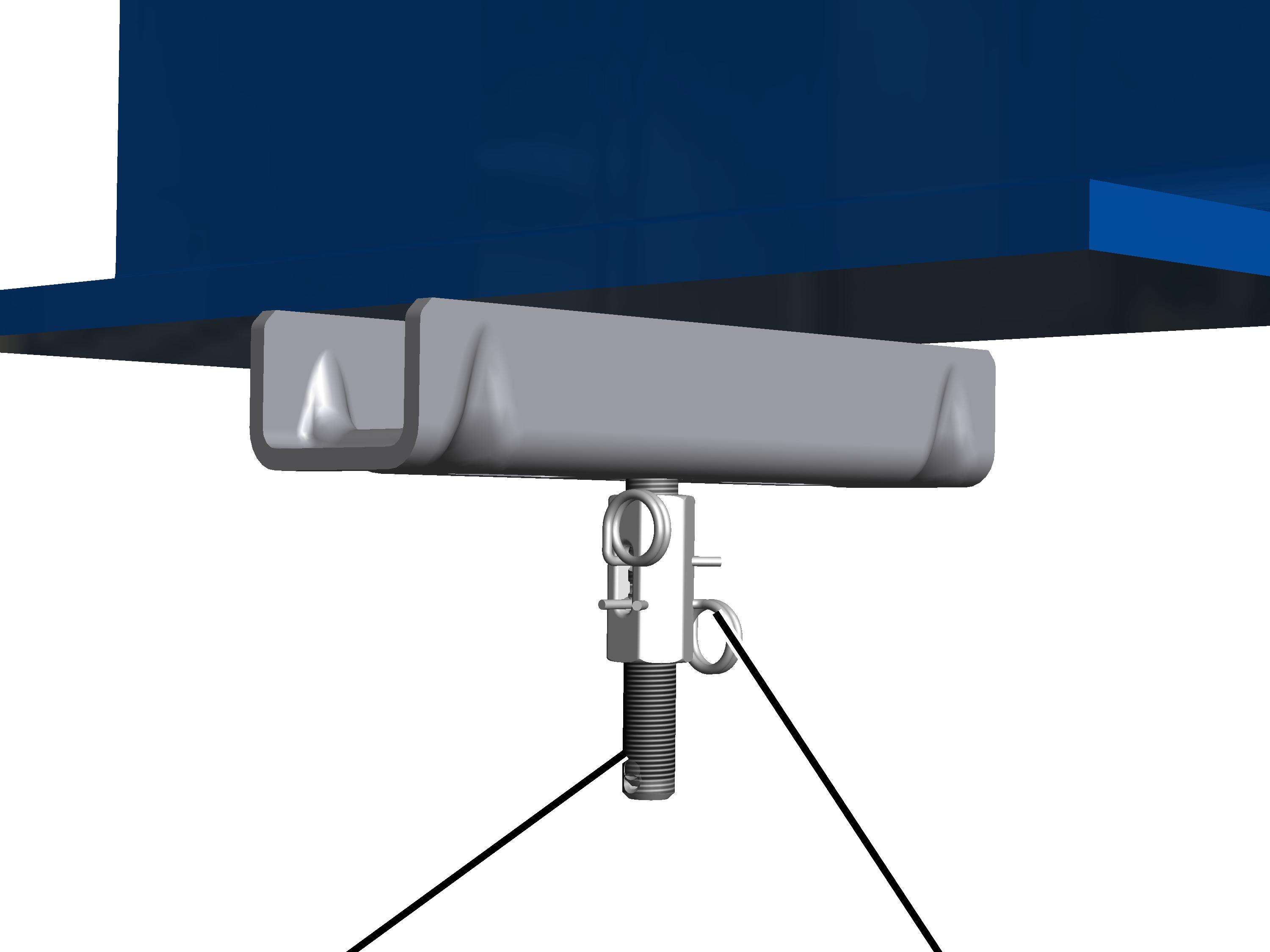
Threaded rod (shortened or lengthened according to version) |
Suspension |
─ The threaded rods with which the crane track is later hung on the ceiling-mounted brackets are then shortened or lengthened. See Shortening or lengthening threaded rods.
─ Next, the suspension is installed on the ceiling-mounted brackets.
There are six different suspensions. Which version is used is in part determined by the supporting structure and the suspension height of the HB crane installation.
o Normal suspension: see Craneway suspension M16: Installing a normal suspension.
o Short suspension: see Craneway suspension M16: Installing a short suspension.
o Inclined suspension: see Craneway suspension M16: installing an inclined suspension.
o Normal stiffener: see Craneway suspension M16: installing a normal stiffener.
o Inclined stiffener: see Craneway suspension M16: installing an inclined stiffener.
o V-suspension: see Craneway suspension M16: installing the V-suspension.
|
|
This product manual describes the suspension on ceiling-mounted brackets 2LP/M16 A, B and C. To install the suspension on ceiling-mounted brackets 2LP/M20 or 4LP/M20, see product manual "Installing the ceiling-mounted bracket 4LP/M20 and craneway suspension M20". |
|
| |
|
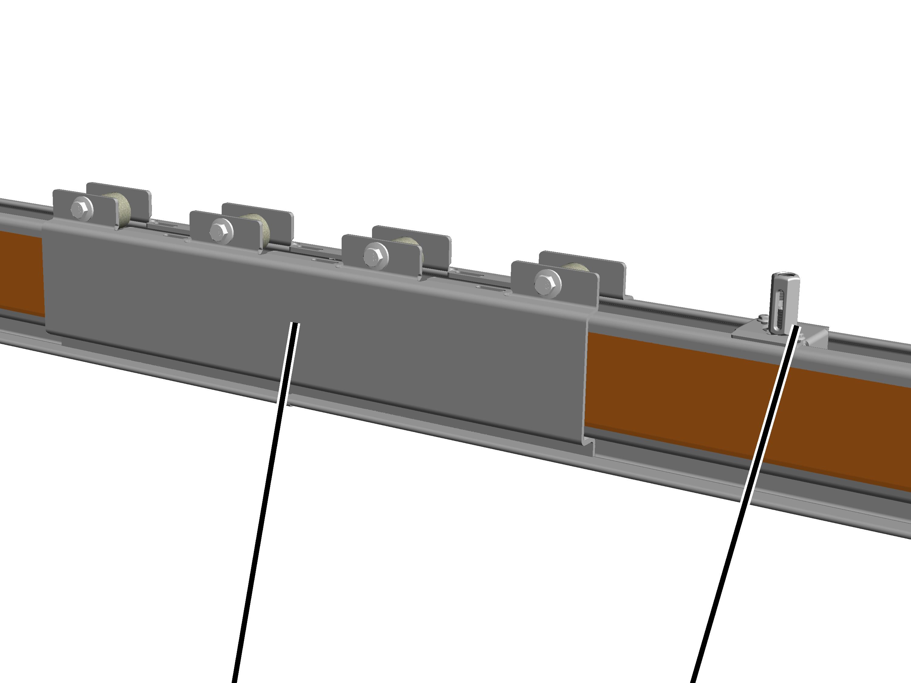
HB profile rail with clamping plates |
Profile connection |
─ Next, the individual profile rail sections are joined together for the crane track. See Connecting steel profile rail sections.
─ Especially with reconstructions, it may be necessary to shorten the profile rail sections on-site.
See Sawing profile rail sections.
─ The profile connections are then laid loosely in the HB profile rails. The profile connections are not bolted on so that they can later be moved freely for installation. See Installing profile connections for craneway suspension M16.
The connected profile rail sections must be able to be raised and brought underneath the suspensions safely and without posing additional hazards.
If this is not possible, the profile rail sections must first be fixed individually or partially joined to the suspension and then afterward fully joined with each other. When doing this, it must be ensured that there is adequate space underneath the suspensions, especially in the case of short suspensions.
|
|
This product manual describes the laying of profile connections for M16 suspensions. To lay profile connections for M20 suspensions: see product manual "Installing the ceiling-mounted bracket 4LP/M20 and craneway suspension M20". |
|
|
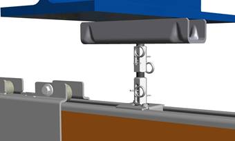
─ The crane track is then bolted to the suspension together with the profile connections. See Installing the HB crane runway on the M16 craneway suspension.
─ Next, the crane track is aligned. See Aligning the crane track.
─ Finally, the crane track is tightly bolted and secured. See Bolting on and securing the crane track to the craneway suspension.
|
|
This product manual describes the installation of the crane track on M16 suspensions. To install the crane track on M20 suspensions: see product manual "Installing the ceiling-mounted bracket 4LP/M20 and craneway suspension M20". |
|
| |
|
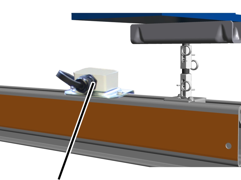
Terminal box |
|
─ A terminal box is mounted on the power line on the crane track. See Installing the terminal box.
|
|
Whether and at which point a terminal box is to be mounted is specified in the planning documents. |
─ The travel mechanisms for crane (EHB, ZHB) or trolley (ESK, ZSK) are then inserted in the crane track. See Inserting the trolleys.
─ If necessary, the HBF drives are then installed. See Installing the HBF drive.
─ If necessary, the anti-collision devices are next inserted in the crane track. See Installing the anti-collision device.
─ The mains power supply is then installed on the crane track.
|
|
Which side and position is intended for the mains power supply is specified in the planning documents. |
There are three different versions of the mains power supply.
|
| |
|
|
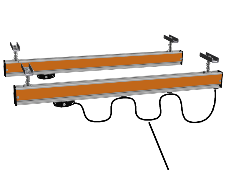
Mains power supply as festoon cable system |
o Festoon cable system: the mains power supply consists of a flat cable which is fastened to cable sliders. These cable sliders are then pulled along by the HB crane. See Installing the festoon cable system.
|
| |
|
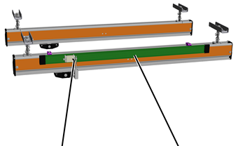
Mains power carrying fork |
Mains power supply as conductor system VKL |
o Conductor system VKL (not with HB240): the mains power supply consists of a conductor system which is mounted on the crane track. In the conductor system, a current collector is pulled along by the HB crane. See Installing the conductor system VKL.
|
| |
|
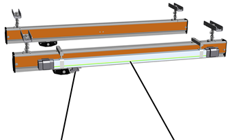
Mains power carrying fork |
Mains power supply as conductor system KBH |
o Conductor system KBH: the mains power supply consists of a conductor system which is mounted on the crane track. In the conductor system, a current collector is pulled along by the HB crane. See Installing the conductor system KBH.
o For the double-rail trolley ZSK there is a further variant of the mains power supply available. This is described in the product manual “Installing the HB crane ZHB or ZSK”.
─ Finally, the mains power supply is connected. See Hauptstromzuführung anschließen.