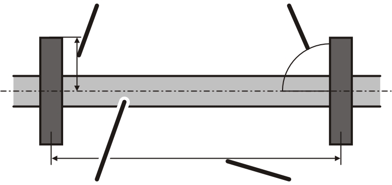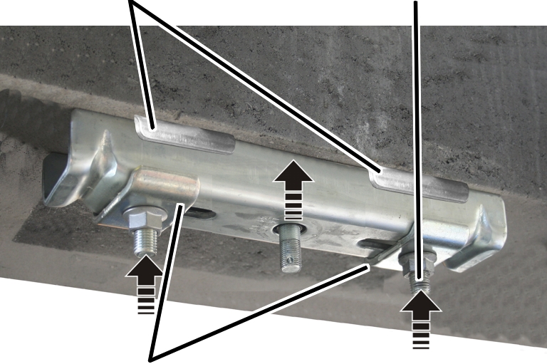
Threaded rod
Articulated girder
The ceiling-mounted bracket 2LP/M16 or M20 is bolted onto two cup square bolts. The cup square bolts are inserted through holes in a concrete element and secured on the other side with counter plates.
|
| |
|
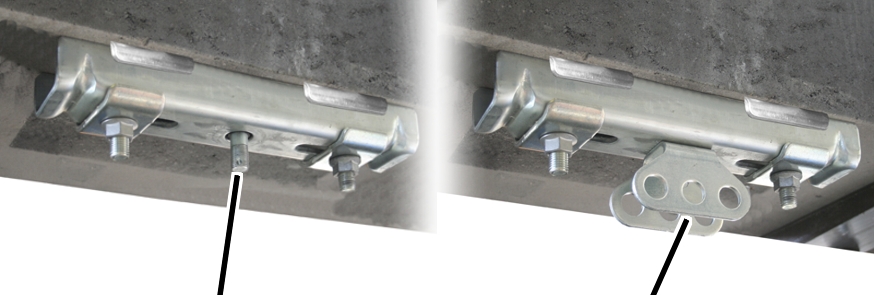
Threaded rod |
Articulated girder |
|
|
The figures show the installation of a ceiling-mounted bracket 2LP/M16 or M20 with projecting threaded rod (with normal suspension, short suspension and normal stiffener). The installation of a ceiling-mounted bracket 2LP/M16 with bolted-on articulated girder (with normal stiffener, inclined suspension, inclined stiffener and V-suspension) does not differ significantly from this. |
|
|
The figures show the installation of a ceiling-mounted bracket 2LP/M16 with bolted-on articulated girder. The installation of ceiling-mounted bracket 2LP/M20 does not essentially differ. |
|
|
The installation of the ceiling-mounted bracket 4LP/M20 is described in the product manual "Installing the ceiling-mounted bracket 4LP/M20 and craneway suspension M20". |
On every ceiling-mounted bracket 2LP/M16 or M20:
|
|
Where and at what intervals the ceiling-mounted brackets are fixed to the supporting structure is specified in the planning documents. |
The specified dimensions, positions and clearances must be followed exactly.
|
Ceiling-mounted bracket centred in relation to HB profile rail |
Ceiling-mounted bracket perpendicular to HB profile rail |
|
| |
|
Later-installed HB profile rail |
Suspension distance LB |
 Position the drilled holes so that the
ceiling-mounted bracket will later be exactly centred in relation to the
later-installed HB profile rail.
Position the drilled holes so that the
ceiling-mounted bracket will later be exactly centred in relation to the
later-installed HB profile rail.
This is necessary so that the HB profile rail can later be aligned.
|
Drilled hole spacing |
Drilled hole diameter |
|
| |
|
Ceiling-mounted bracket |
HB profile rail |
 On the other side of the concrete
element, press a wooden beam (for example) against the exit point of the drill.
This ensures the concrete element does not crumble as much during the
drilling.
On the other side of the concrete
element, press a wooden beam (for example) against the exit point of the drill.
This ensures the concrete element does not crumble as much during the
drilling.
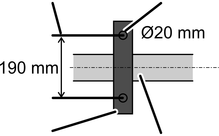
Observe occupational safety
regulations and use a suitable impact drill (appropriate for the material of the
concrete element) to drill two thru-holes in the concrete element:
─ Drilled hole diameter: 20 mm
─ Drilled hole spacing: 190 mm
On every ceiling-mounted bracket 2LP/M16 or M20:
|
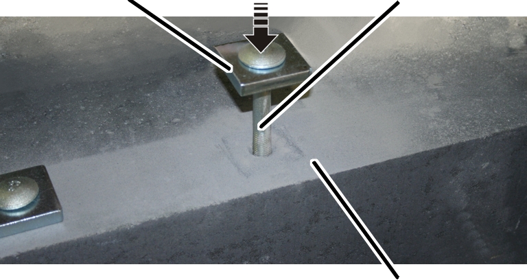
Counter plate |
Cup square bolt |
|
| |
|
|
Concrete element |
Insert cup square bolts (2x) with
counter plate (1x each) through the concrete element from above.
This section only applies to the ceiling-mounted bracket 2LP/M16 with bolted-on articulated girder (with normal stiffener, inclined suspension, inclined stiffener and V-suspension)
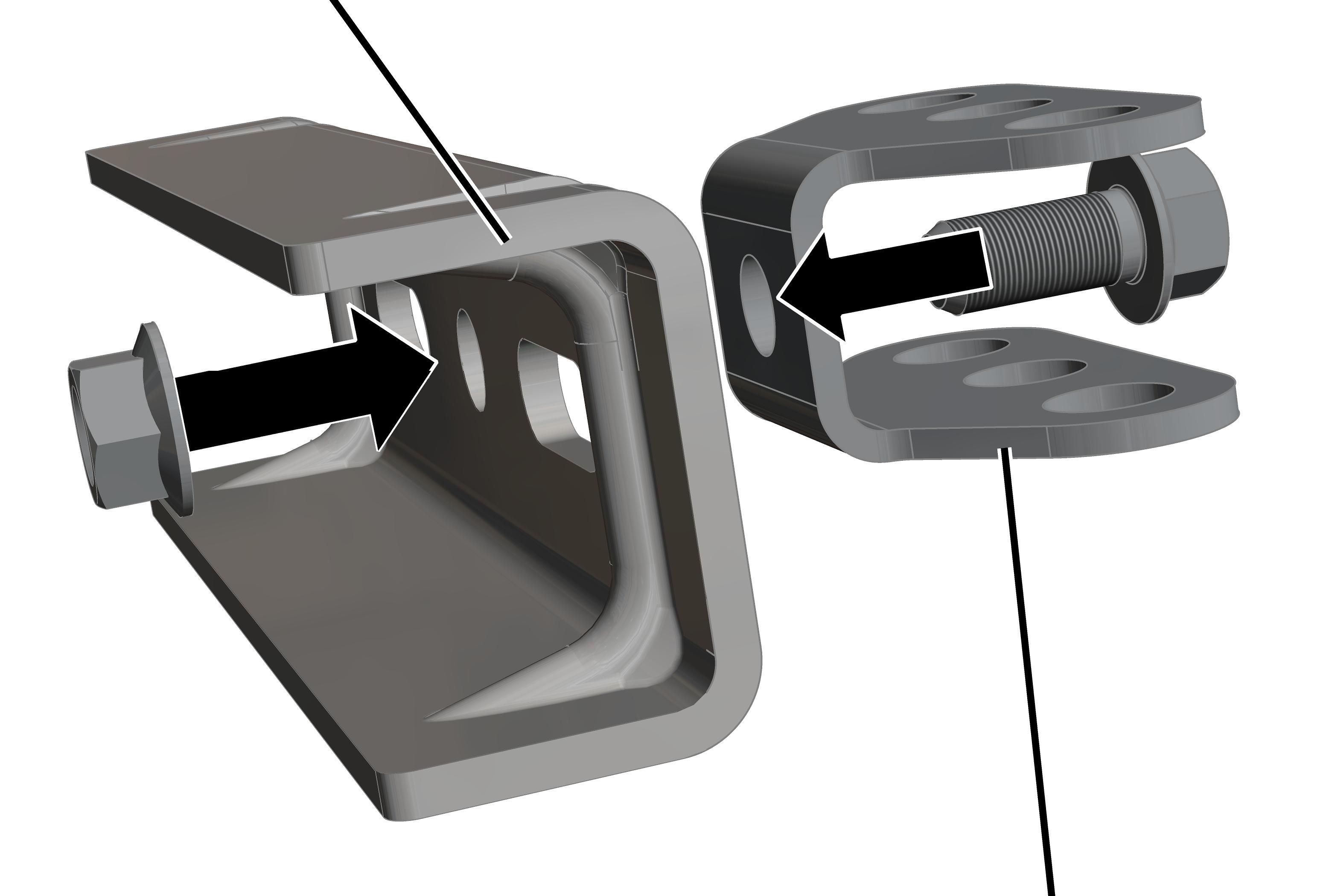
On every ceiling-mounted bracket 2LP/M16 with articulated girder:
The articulated girders can be mounted lengthwise or crosswise to the ceiling-mounted bracket 4LP/M20 as appropriate for the alignment of the supporting structure.
|
Ceiling-mounted bracket |
|
|
| |
|
|
Articulated girder |
Insert M16x35 rib screw through
articulated girder.
Insert articulated girder with rib
screw in ceiling-mounted bracket.
Screw the M16 rib nut loosely onto the
rib screw from the back.
Shift the articulated girder
lengthwise or crosswise to the ceiling-mounted bracket as necessary.
Screw the rib nut on. 300 Nm.
On every ceiling-mounted bracket 2LP/M16 or M20:
|
Retaining plates |
Cup square bolt |
|
| |
|
Clamping plates |
|
Insert retaining plates (2x),
ceiling-mounted bracket (1x) and clamping plates (2x) on the cup square bolt
from below.
Loosely screw on the ceiling-mounted
bracket with the M16 rib nuts (2x).
Position the ceiling-mounted bracket
so that it is exactly centred in relation to the later-installed HB profile
rail.
This is necessary so that the HB profile rail can later be aligned far enough to the left or right. The ceiling-mounted bracket can later be shifted 12 mm to the left or right.
Screw on the M16 rib nuts (2x)
initially hand-tight.
The rib nuts will later be tightened to the correct torque (after aligning the HB profile rail).
If final alignment of the ceiling-mounted bracket 2LP/M16 or M20 can now be done:
Screw the rib nuts tight.
90 Nm.