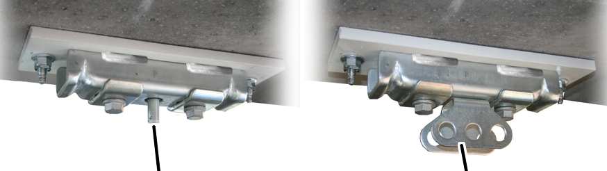
Threaded rod
Articulated girder
The ceiling-mounted bracket 2LP/M16 or M20 is bolted to a dowel plate, which in turn is dowelled with anchor rods to a concrete ceiling.
|
| |
|
Threaded rod |
Articulated girder |
|
|
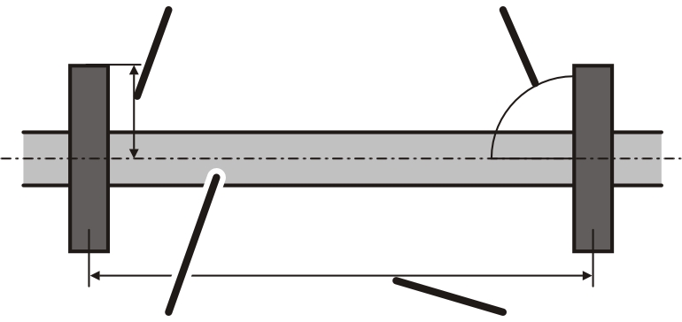
The figures show the installation of a ceiling-mounted bracket 2LP/M16 or M20 with projecting threaded rod (with normal suspension, short suspension and normal stiffener). The installation of a ceiling-mounted bracket 2LP/M16 with bolted-on articulated girder (with normal stiffener, inclined suspension, inclined stiffener and V-suspension) does not differ significantly from this. |
|
|
The figures show the installation of a ceiling-mounted bracket 2LP/M16 with bolted-on articulated girder. The installation of ceiling-mounted bracket 2LP/M20 does not essentially differ. |
|
|
The installation of the ceiling-mounted bracket 4LP/M20 is described in the product manual "Installing the ceiling-mounted bracket 4LP/M20 and craneway suspension M20". |
|
|
Where and at what suspension intervals the ceiling-mounted brackets are fixed to the supporting structure is specified in the planning documents. |
|
|
In addition, all dowel dimensions such as drilled hole depths, edge clearances etc. are specified in the planning documents. |
The specified dimensions, positions and clearances must be followed exactly.
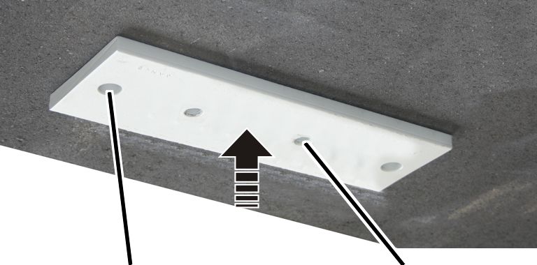
First, only one of the holes is drilled, the anchor rod is fixed within it and, after the injection mortar hardens, the dowel plate is bolted on. The other drilled holes are only drilled afterwards through the hole in the tightly bolted-on dowel plate. Otherwise the drilled holes could go astray during the drilling and no longer align.
|
Ceiling-mounted bracket centred in relation to HB profile rail |
Ceiling-mounted bracket perpendicular to HB profile rail |
|
| |
|
Later-installed HB profile rail |
Suspension distance LB |
 Position the dowel plate as specified in the
planning documents.
Position the dowel plate as specified in the
planning documents.
Align the dowel plate so that it is
lengthwise exactly perpendicular to the later-installed HB profile rail.
Position the dowel plate so that it is
exactly centred in relation to the later-installed HB profile rail.
This is necessary so that the HB profile rail can later be aligned.
|
| |
|
Drilled hole |
Dowel plate |
Thoroughly sweep and clean the entire
assembly area.
 Mark a hole of the dowel plate on the
supporting structure.
Mark a hole of the dowel plate on the
supporting structure.
Depending on the load capacity, the dowel plate as two or four holes.
|
| |
|
|
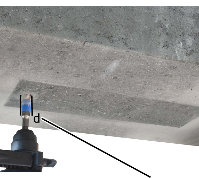
Drilled hole diameter |
Clamp the carbide masonry drill bit
with the correct diameter in the hammer drill.
Only use drill bits that bear the inspection mark of the appropriate testing authority (in Germany: Remscheid).
|
Anchor rod |
Drilled hole diameter d |
|
M12 |
14 mm |
|
M16 |
18 mm |
This section only applies if the HB crane installation is to be dowelled to pre-fabricated, fully cast or other concrete elements.
|
Concrete cover |
|
|
| |
|
Drilled hole depth |
|
All dimensions for the dowelled anchor rods such as drilled hole depths, edge clearances etc. are specified in the planning documents. These specifications must be followed exactly.
|
Anchor rod |
Drilled hole depth from lower edge of supporting structure h |
Concrete cover (drilled hole base to top edge of concrete ceiling) |
|
M12 |
min. 105 mm |
min. 25 mm |
|
M16 |
min. 130 mm |
min. 30 mm |
Drill holes.
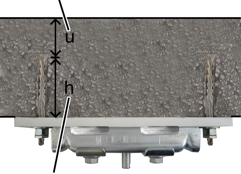
This section only applies if the anchor rod is to be dowelled in composite decks (e.g. filigree deck slabs).
|
Concrete cover |
Drilled hole depth, in-situ concrete | |
|
| ||
|
Drilled hole depth |
Drilled hole depth, semi-precast element | |
The anchor rod must therefore be fully anchored in the in-situ concrete for “Drilled hole depth, in-situ concrete”.
Observe the drilled hole depth in the
in-situ concrete and concrete cover.
All dimensions for the dowelled anchor rods such as drilled hole depths, edge clearances etc. are specified in the planning documents. These specifications must be followed exactly.
|
Anchor rod |
Drilled hole depth, in-situ concrete (ho) |
Concrete cover (drilled hole base to top edge of concrete ceiling (u)) |
|
M12 |
min. 105 mm |
min. 25 mm |
|
M16 |
min. 130 mm |
min. 30 mm |
Add the
thickness of the semi-precast element to the drilled hole depth of the in-situ
concrete.
Total drilled hole depth = Drilled hole depth in in-situ concrete + thickness of semi-precast element
The semi-precast element must not exceed a maximum thickness of 70 mm.
To compensate for the additional thickness of the non-load-bearing semi-precast element, anchor rods with a greater overall length are supplied for composite decks.
Hold the hammer drill exactly vertical
and drill the hole.
|
Drilled hole |
| |
|
| ||
|
Vacuum cleaner |
Compressed air | |
Blow out the drilled holes from the
base of the hole at least twice with a blow-out pump or with oil-free compressed
air and vacuum up the drill dust.
|
|
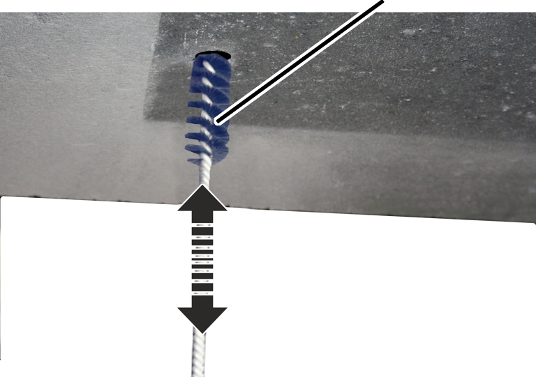
Drilled hole brush |
|
| |
 Brush out the drilled holes twice with
the drilled hole brush.
Brush out the drilled holes twice with
the drilled hole brush.
 Blow out the drilled holes and suction
out the drill dust twice more.
Blow out the drilled holes and suction
out the drill dust twice more.
|
| |
|
|
Anchor rod |
By way of a trial, insert the anchor
rods completely into the drilled holes. The shaft with the cones must be
completely in the drilled hole exactly up to the start of the thread.
If a drilled hole is not deep enough:
Re-drill and clean the hole as
previously described.
|
Static mixer | ||
|
| ||
|
Cartridge applicator gun |
| |
Unscrew the capsule seal.
Screw on the static mixer.
Place the capsule in the pressure
gun.
|
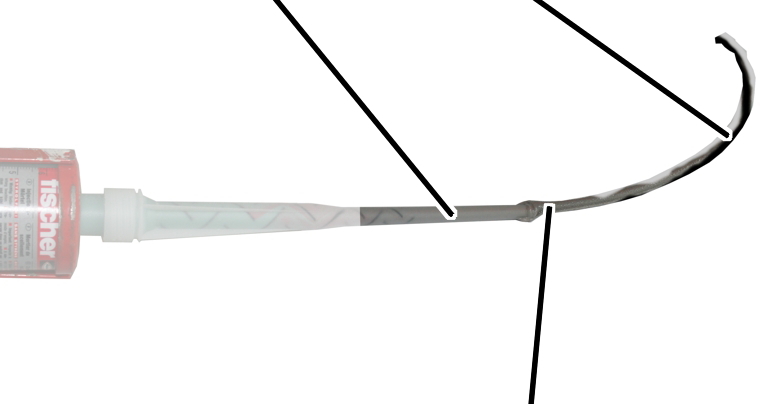
Tip of static mixer |
Unmixed injection mortar |
|
| |
|
|
Mixed injection mortar, grey |
Press injection mortar out of the
capsule until the injection mortar emerging has been uniformly mixed and is
clearly grey in colour. Do not use injection mortar that is not grey in
colour.
─ In the event of interruptions (e.g. between two dowel fittings), do not unscrew the static mixer from the capsule.
─ After each interruption, squeeze out two gun strokes of unused injection mortar and do not use.
─ After longer breaks, screw on a new static mixer and again squeeze out the injection mortar for as long as is needed until the discharged injection mortar is a clearly grey colour.
─ Injection mortar which is not grey is not mixed correctly and will not set. Do not use any injection mortar which is not grey coloured!
─ Setting time of the injection mortar:
|
Temperature of the capsule |
Setting time [min] |
|
5 °C |
15 min |
|
20 °C |
6 min |
|
+30 °C |
4 min |
|
|
Scale |
|
| |
Read off the necessary quantity of
injection mortar from the table. From the base of the drilled hole, fill the
drilled hole with injection mortar without any bubbles. Read off the quantity
used to fill the hole from the scale on the capsule.
|
Drilled hole |
Quantity of injection mortar required |
|
At least 8 scale units | |
|
M16 |
At least 10 scale units |
Continue immediately with the next
work step (see Inserting
the anchor rod in the drilled hole). Otherwise the injection mortar will
harden and become unusable.
|
| |
|
| |
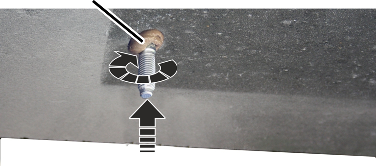
Rotate the anchor rod slightly
(without spherical washer and hexagonal nuts) and while doing so, press it into
the drilled hole. Press the anchor rod in so far that the shaft with the cones
is completely in the drilled hole exactly up to the start of the thread.
● In the process, some injection mortar will emerge from the drilled hole.
● Only with composite decks: since the anchor rod is only anchored in the in-situ concrete, but the semi-precast element still lies beneath the in-situ concrete, no injection mortar will emerge from the hole.
If no injection mortar comes out of the drilled hole:
Pull the anchor rod immediately out of
the drilled hole.
Fill up the drilled hole with
additional injection mortar.
Insert the anchor rod again as
described.
Continue immediately with the next
work step (see Wiping
off injection mortar). Otherwise the injection mortar will harden and the
dowel plate can no longer be fitted flat.
Wipe off the injection mortar that has come out
of the hole.
Otherwise the dowel plate cannot be bolted flat under the concrete ceiling later.
|
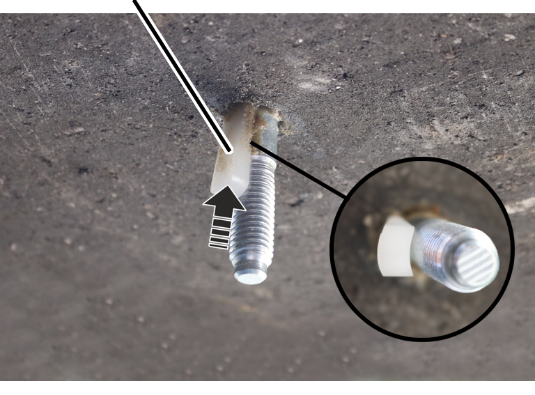
Wedge |
|
|
| |
Turn the wedge with the concave side
towards the anchor rod and push it into the drilled hole.
Push the wedge until the anchor rod is
safely in the drilled hole and does not slip out.
● The anchor rod is pushed slightly to the side by this. This is not of any significance for further installation work.
Allow the injection mortar to harden.
|
Temperature in concrete ceiling |
Hardening time [min] |
|
-5 °C to 0 °C |
360 min |
|
+1 °C to +5 °C |
180 min |
|
+6 °C to +10 °C |
90 min |
|
+11 °C to +20 °C |
35 min |
|
+21 °C to +30 °C |
20 min |
|
+31 °C to +40 °C |
12 min |
Table: Hardening times for a dry concrete ceiling. Double the times for damp or wet concrete.
Tip:
The time during which the injection mortar is hardening can be used to install the first anchor rod on other dowel plates.
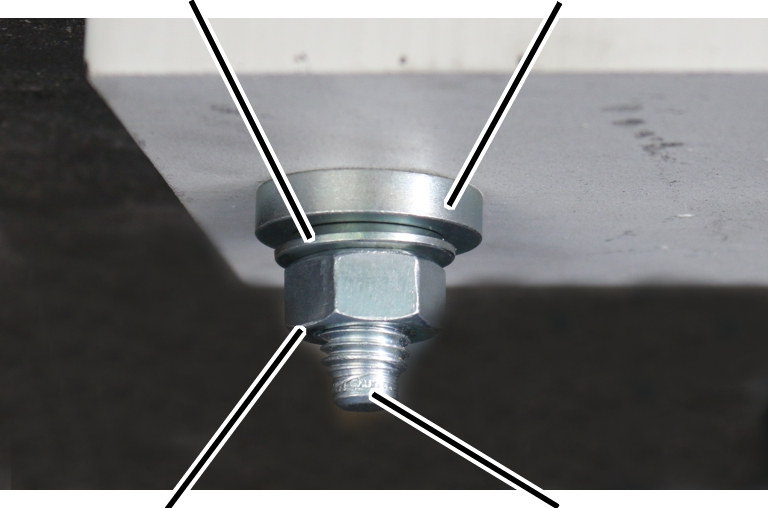
After the injection mortar has hardened around the first anchor rod:
|
|
Clamping bush |
|
| |
|
Dowel plate |
Anchor rod |
Remove the projecting part of the
wedge.
Push the dowel plate with the hole
without thread onto the installed anchor rod.
Do not use the holes with thread. The ceiling-mounted bracket is installed using these later.
Align the dowel plate as described at
the beginning.
Place the clamping bush on the anchor
rod.
Push the assembly aid on the anchor
rod.
Knock in the clamping bush using a
hammer and the assembly aid until the lower end of the clamping bush is flush
with the lower edge of the dowel plate.
|
Spherical washer |
Ball socket |
|
| |
|
Hexagonal nut |
Anchor rod |
Insert the ball socket on the anchor
rod.
Insert the spherical washer.
Screw the M12 or M16 hexagonal nut to
the anchor rod and tighten it carefully so that the dowel plate can no longer be
twisted.
● The dowel plate is located firmly under the concrete ceiling and serves as a template for the other drilled holes.
Drill through the dowel plate into the
concrete ceiling at all additional holes in the dowel plate (one or three
additional holes).
The dowel plate serves here as a template.
Clean the drilled holes, check the
drilled holes, prepare the capsule, fill the drilled hole with injection mortar,
screw the anchor rod into the drilled hole, wipe the injection mortar off, allow
the injection mortar to harden and screw the dowel plate on as described
above.
The wedge is only used for the first anchor rod.
As soon as the injection mortar has hardened:
Tighten all hexagonal nuts with the
correct torque.
|
Anchor rod |
Tightening torque |
|
M12 |
40 Nm |
|
M16 |
60 Nm |
If the hexagonal nuts cannot be tightened with the necessary tightening torque (e.g. because the anchor rod turns with them), the anchor rod is not fitted correctly.
In this case:
─ Do not continue installing the HB crane installation.
─ Call ABUS for further instructions.
|
|
Lock nut | |
|
| ||
|
|
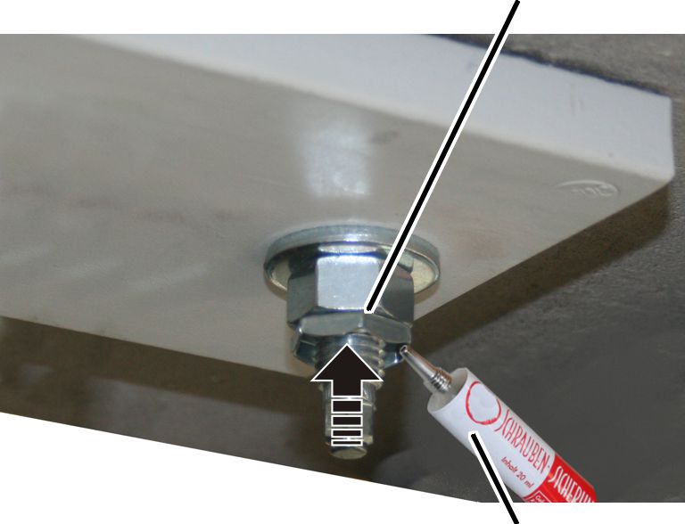
Sealing wax | |
Screw the lock nuts to the anchor
rods. Screw until hand-tight.
Seal the hexagonal nuts, lock nuts and
anchor rods with sealing wax.
Do not cut off protruding anchor rods:
Technical data is stamped on the heads of the anchor rods. This enables later identification of the anchor rods. For this reason, the protruding parts of the anchor rods should not be cut off.
Complete the dowel protocol and add it
to the crane test log book.
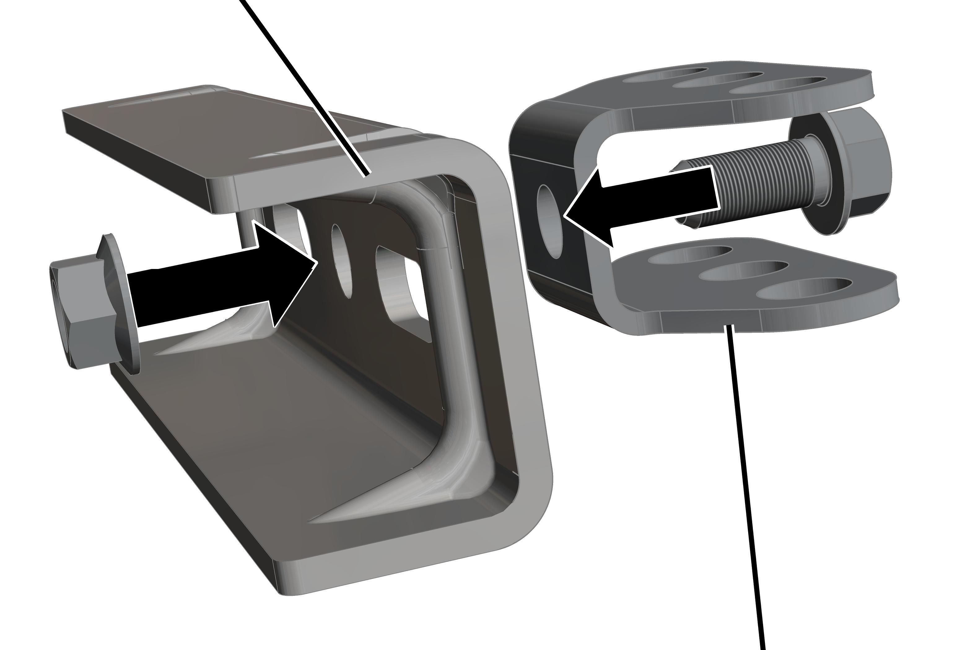
This section only applies to the ceiling-mounted bracket 2LP/M16 with bolted-on articulated girder (with normal stiffener, inclined suspension, inclined stiffener and V-suspension)
On every ceiling-mounted bracket 2LP/M16 with articulated girder:
The articulated girders can be mounted lengthwise or crosswise to the ceiling-mounted bracket 4LP/M20 as appropriate for the alignment of the supporting structure.
|
Ceiling-mounted bracket |
|
|
| |
|
|
Articulated girder |
Insert M16x35 rib screw through
articulated girder.
Insert articulated girder with rib
screw in ceiling-mounted bracket.
Screw the M16 rib nut loosely onto the
rib screw from the back.
Shift the articulated girder
lengthwise or crosswise to the ceiling-mounted bracket as necessary.
Screw the rib nut on. 300 Nm.
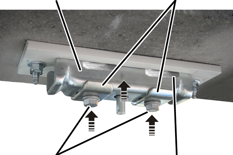
On every ceiling-mounted bracket 2LP/M16 or M20:
|
Ceiling-mounted bracket |
Clamping plate |
|
| |
|
Rib screws |
Retaining plate |
Insert the M16x70 rib screws (2x)
through the clamping plates (2x), ceiling-mounted bracket (1x) and retaining
plates (2x).
Hold the ceiling-mounted bracket under
the dowel plate and loosely screw in the rib screws.
First, screw in M16x70 rib screws (2x)
until hand-tight.
The rib screws will later be tightened to the correct torque (after aligning the HB profile rail).
If final alignment of the ceiling-mounted bracket 2LP/M16 or M20 can now be done:
Screw in the rib screws.
200 Nm.