This product manual describes the installation of an M16 suspension. To install an M20 suspension, see product manual "Installing the ceiling-mounted bracket 4LP/M20 and craneway suspension M20".
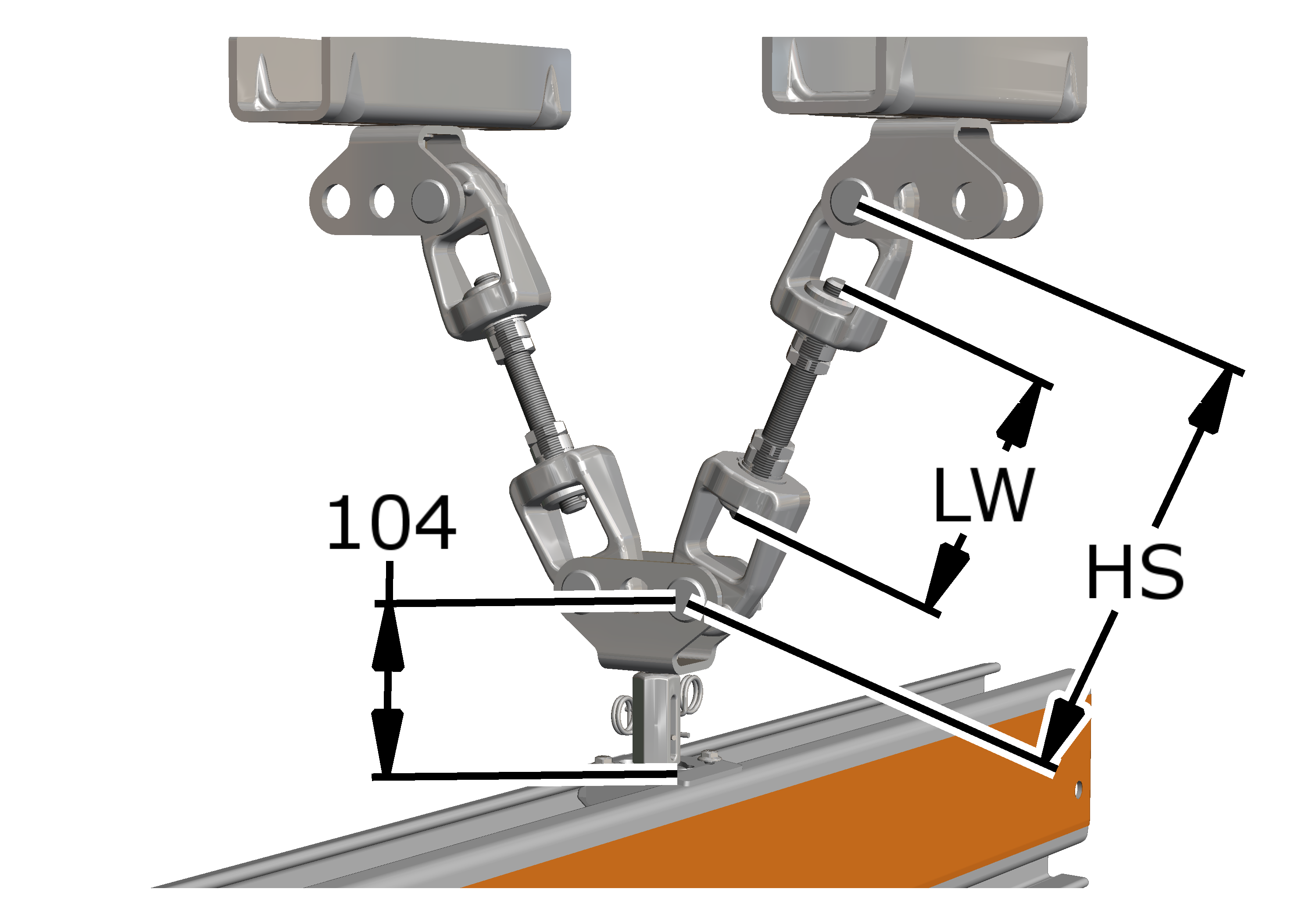
The threaded rods from which the crane track will later be hung are now fitted on the installed ceiling-mounted bracket for the V-suspension.
|
|
This product manual describes the installation of an M16 suspension. To install an M20 suspension, see product manual "Installing the ceiling-mounted bracket 4LP/M20 and craneway suspension M20". |
Overview:
|
|
|
Size |
HS |
|
HB110 |
HS = 80 + LW ± 30 mm |
|
HB150 |
HS = 80 + LW ± 30 mm |
|
HB190 |
HS = 80 + LW ± 30 mm |
|
HB240 |
HS = 80 + LW ± 30 mm |
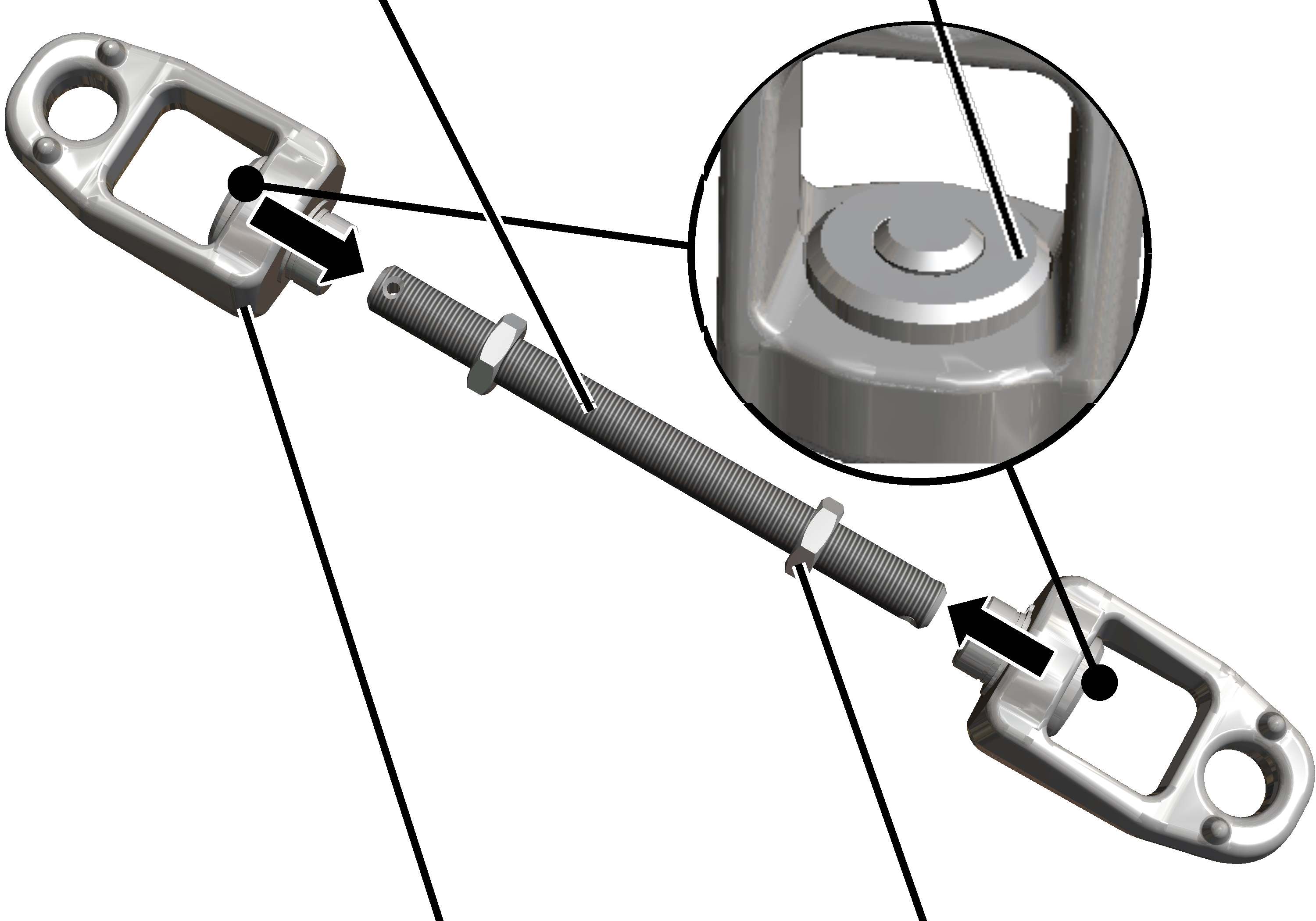
On both ends of the two threaded rods:
|
Threaded rod |
|
|
| |
|
Clamping joint |
Hexagonal nut |
 Screw the M16x1.5 hexagonal nuts (2x) onto the shortened or
lengthened threaded rod.
Screw the M16x1.5 hexagonal nuts (2x) onto the shortened or
lengthened threaded rod.
Screw the threaded rod into the tension nuts (2x) until the end of
the threaded rod is flush with the tension nut on the inside (see enlarged
section of the illustration).
 Lock with hexagonal nut.
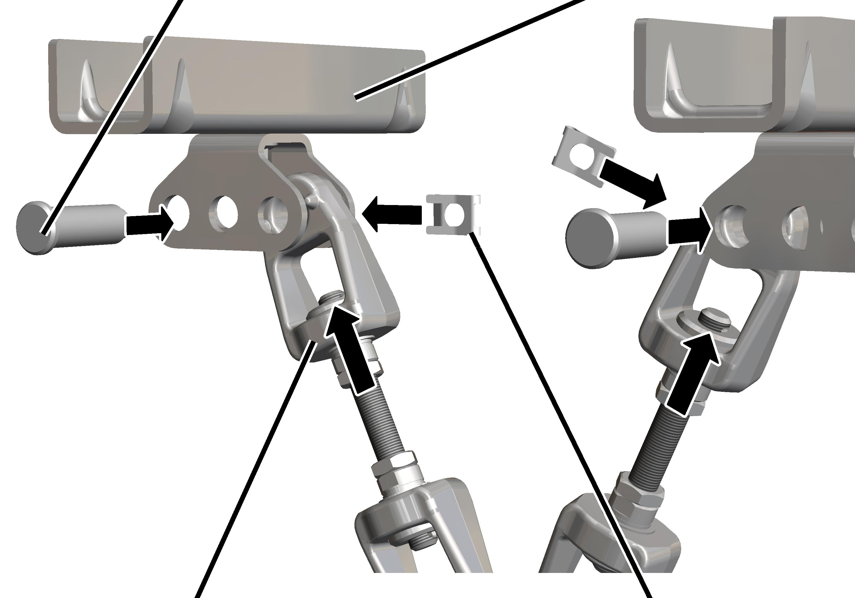
On both ceiling-mounted brackets:
|
Bolt |
Ceiling-mounted bracket |
|
| |
|
Clamping joint |
SL safety clip |
Insert the clamping joint between the articulated girders on the
ceiling-mounted bracket of the V-suspension. Always use the inner hole.
Insert bolt through articulated girder and clamping joint.
Secure bolt with SL safety clip.
A later height adjustment is not possible on the articulated girder of the V-suspension.
The height can only be altered through the length of the two inclined threaded rods.
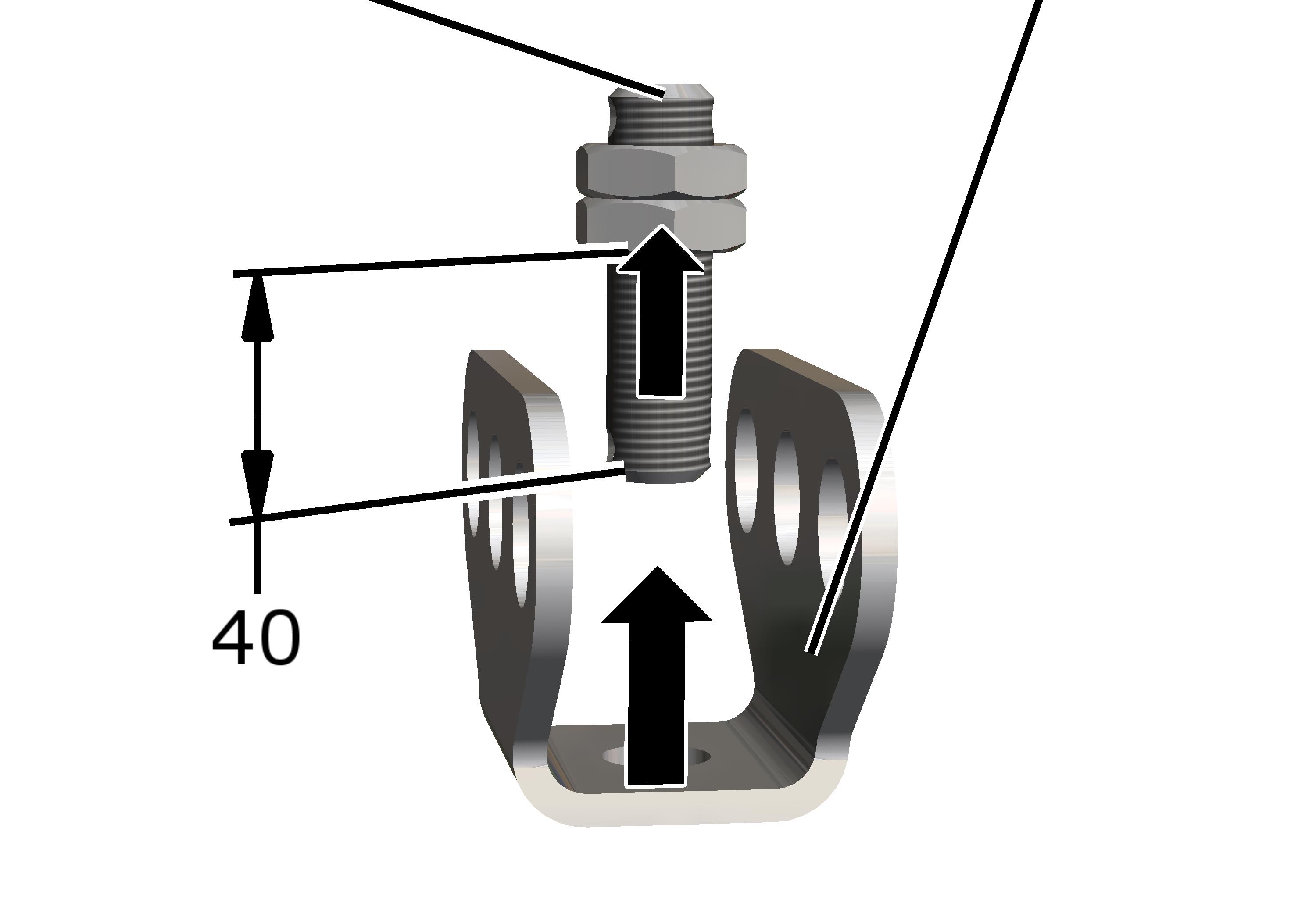
|
Threaded rod |
Articulated girder |
|
| |
Screw the M16x1.5 hexagonal nuts (2x) about 40 mm onto the
threaded rod (80 mm long).
Insert the articulated girder on the threaded rod.
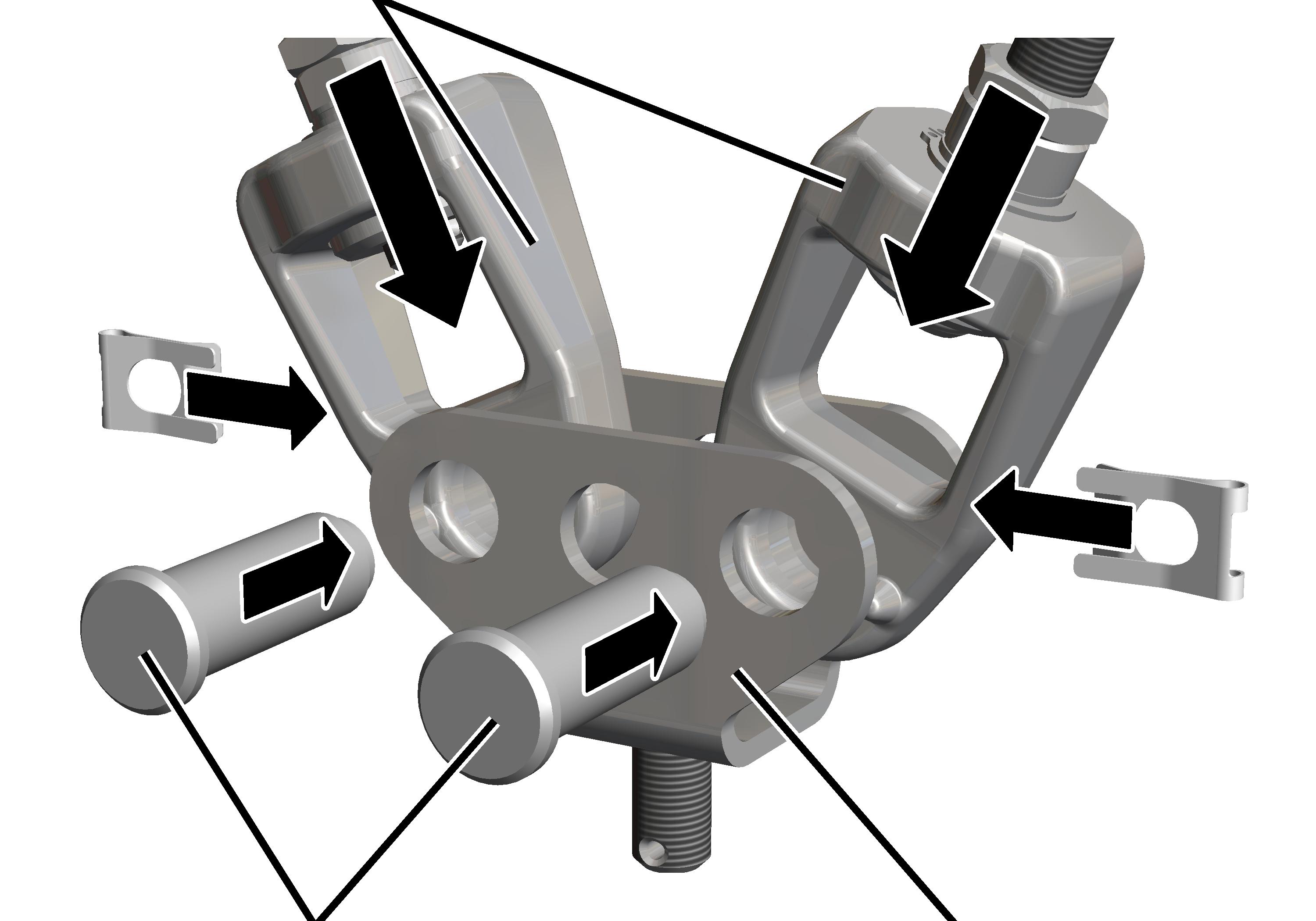
On the lower end of the threaded rods:
|
Clamping joint |
|
|
| |
|
Bolt |
Articulated girder of the V-suspension |
Insert the clamping joints between the articulated girders of the
V-suspension. Use the two outer holes.
Insert bolt through articulated girder and clamping joint.
Secure bolt with SL safety clip.
The HB crane runway will later be installed on the lower end of the threaded rod.