|
|
|
|
Material thickness |
Material quality |
|
Thru-holes and rib nuts |
Maximally 28 mm |
At least S235 |
|
Threaded hole and rib screw |
At least 16 mm |
At least S235 |
|
Ceiling-mounted bracket 2LP/M16 or M20 |
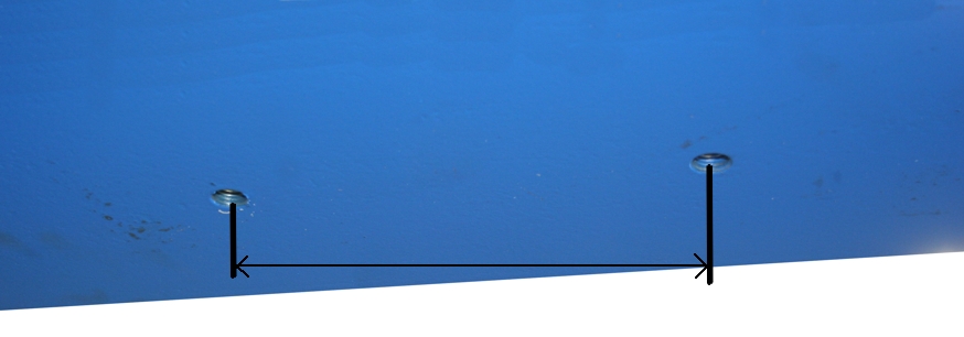
Minimum spacing of boreholes |
Maximum spacing of boreholes |
|
Ceiling-mounted bracket A |
90 mm |
140 mm |
|
Ceiling-mounted bracket B |
140 mm |
240 mm |
|
Ceiling-mounted bracket C |
240 mm |
330 mm |
|
| |
|
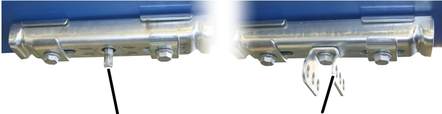
Threaded rod |
Articulated girder |
|
|
The figures show the installation of a ceiling-mounted bracket 2LP/M16 or M20 with projecting threaded rod (with normal suspension, short suspension and normal stiffener). The installation of a ceiling-mounted bracket 2LP/M16 with bolted-on articulated girder (with normal stiffener, inclined suspension, inclined stiffener and V-suspension) does not differ significantly from this. |
|
|
The figures show the installation of a ceiling-mounted bracket 2LP/M16 with bolted-on articulated girder. The installation of ceiling-mounted bracket 2LP/M20 does not essentially differ. |
|
|
The installation of the ceiling-mounted bracket 4LP/M20 is described in the product manual "Installing the ceiling-mounted bracket 4LP/M20 and craneway suspension M20". |
This section only applies to the ceiling-mounted bracket 2LP/M16 with bolted-on articulated girder (with normal stiffener, inclined suspension, inclined stiffener and V-suspension)
On every ceiling-mounted bracket 2LP/M16 with articulated girder:
The articulated girders can be mounted lengthwise or crosswise to the ceiling-mounted bracket 4LP/M20 as appropriate for the alignment of the supporting structure.
|
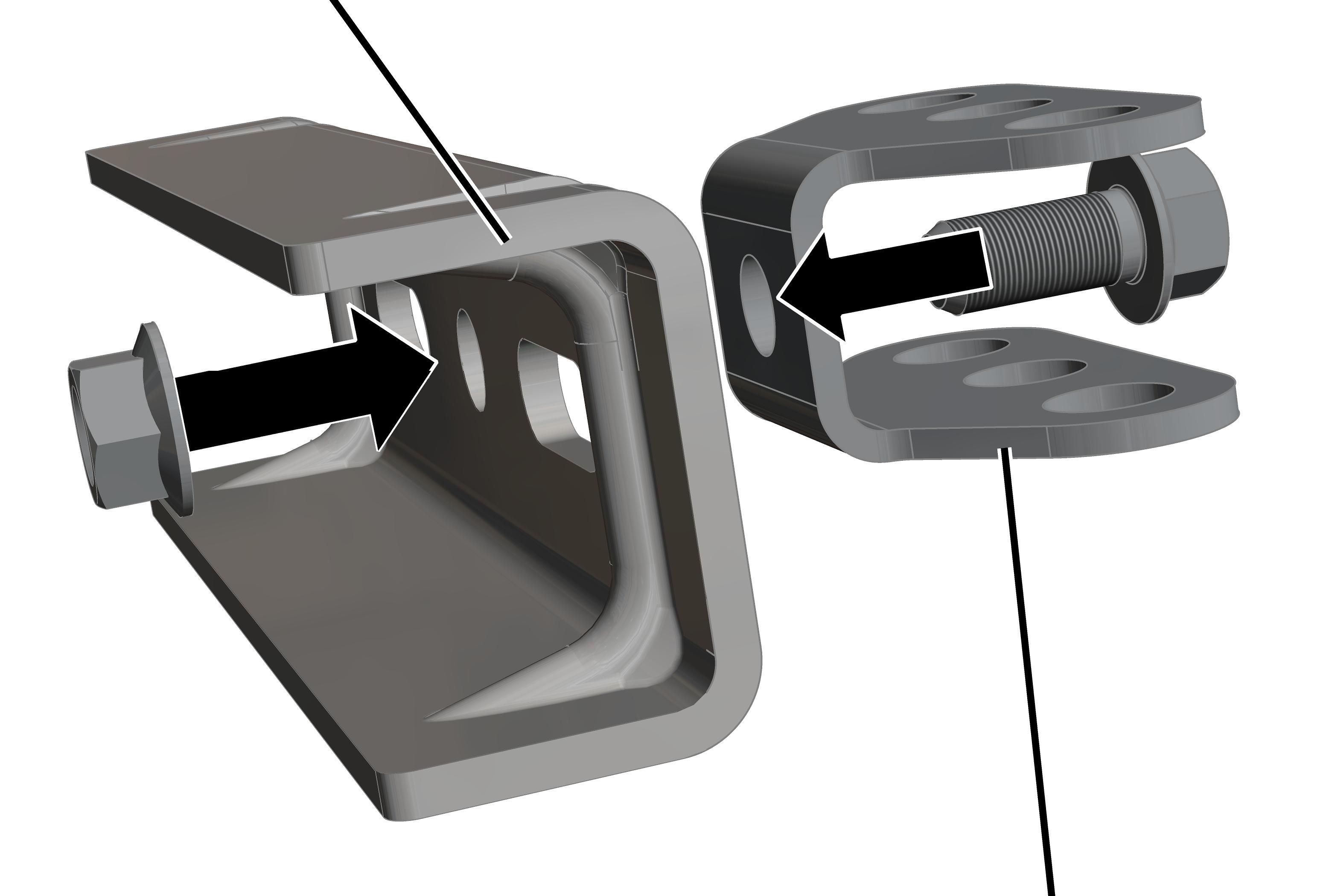
Ceiling-mounted bracket |
|
|
| |
|
|
Articulated girder |
 Insert M16x35 rib screw through
articulated girder.
Insert M16x35 rib screw through
articulated girder.
Insert articulated girder with rib
screw in ceiling-mounted bracket.
Screw the M16 rib nut loosely onto the
rib screw from the back.
Shift the articulated girder
lengthwise or crosswise to the ceiling-mounted bracket as necessary.
Screw the rib nut on. 300 Nm.
On every ceiling-mounted bracket 2LP/M16 or M20:
|
|
Where and at what intervals the ceiling-mounted brackets are fixed to the supporting structure is specified in the planning documents. |
The specified dimensions, positions and clearances must be followed exactly.
|
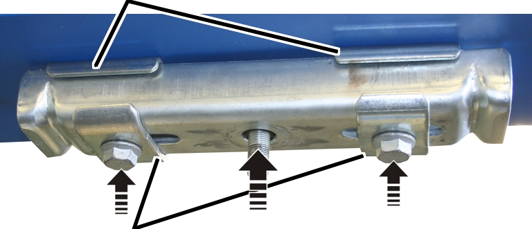
Retaining plates |
|
|
| |
|
Clamping plates |
|
Insert the rib screws (2x) through the
clamping plates (2x), ceiling-mounted bracket (1x) and retaining plates
(2x).
|
|
Rib screw |
|
Thru-holes and rib nuts |
M16x90 |
|
Threaded hole and rib screw |
M16x70 |
 Hold the ceiling-mounted bracket under
the holes and loosely screw in the rib screws.
Hold the ceiling-mounted bracket under
the holes and loosely screw in the rib screws.
|
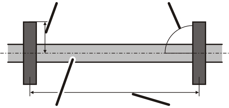
Ceiling-mounted bracket centred in relation to HB profile rail |
Ceiling-mounted bracket perpendicular to HB profile rail |
|
| |
|
Later-installed HB profile rail |
Suspension distance LB |
Align the ceiling-mounted bracket so
that it lies lengthwise exactly perpendicular to the later-installed HB profile
rail.
Position the ceiling-mounted bracket
so that it is exactly centred in relation to the later-installed HB profile
rail.
This is necessary so that the HB profile rail can later be aligned.
Screw in the rib screws (2x) initially
hand-tight.
The rib screws will later be tightened to the correct torque (after aligning the HB profile rail).
If final alignment of the ceiling-mounted bracket 2LP/M16 or M20 can now be done:
Screw in the rib screws.
The correct tightening torque depends on the bolt quality and the friction coefficient from the standards table.
Example: 200 Nm for M16, bolt quality grade 8.8 and friction coefficient 0.12.