The figures show the installation of a conductor system KBH on a steel HB profile rail. The installation on aluminium HB profile rails does not essentially differ.
Additionally observe the supplied documentation of the conductor system KBH.
|
|
The figures show the installation of a conductor system KBH on a steel HB profile rail. The installation on aluminium HB profile rails does not essentially differ. |
 Lay out the individual sections of the conductor system on the floor
as they will later be installed on the HB profile rail.
Lay out the individual sections of the conductor system on the floor
as they will later be installed on the HB profile rail.
|
|
What position is intended for the power line is specified in the planning documents. |
 Turn the sections so that the protective conductor marking
(yellow-green line) points in the same direction at all points.
Turn the sections so that the protective conductor marking
(yellow-green line) points in the same direction at all points.
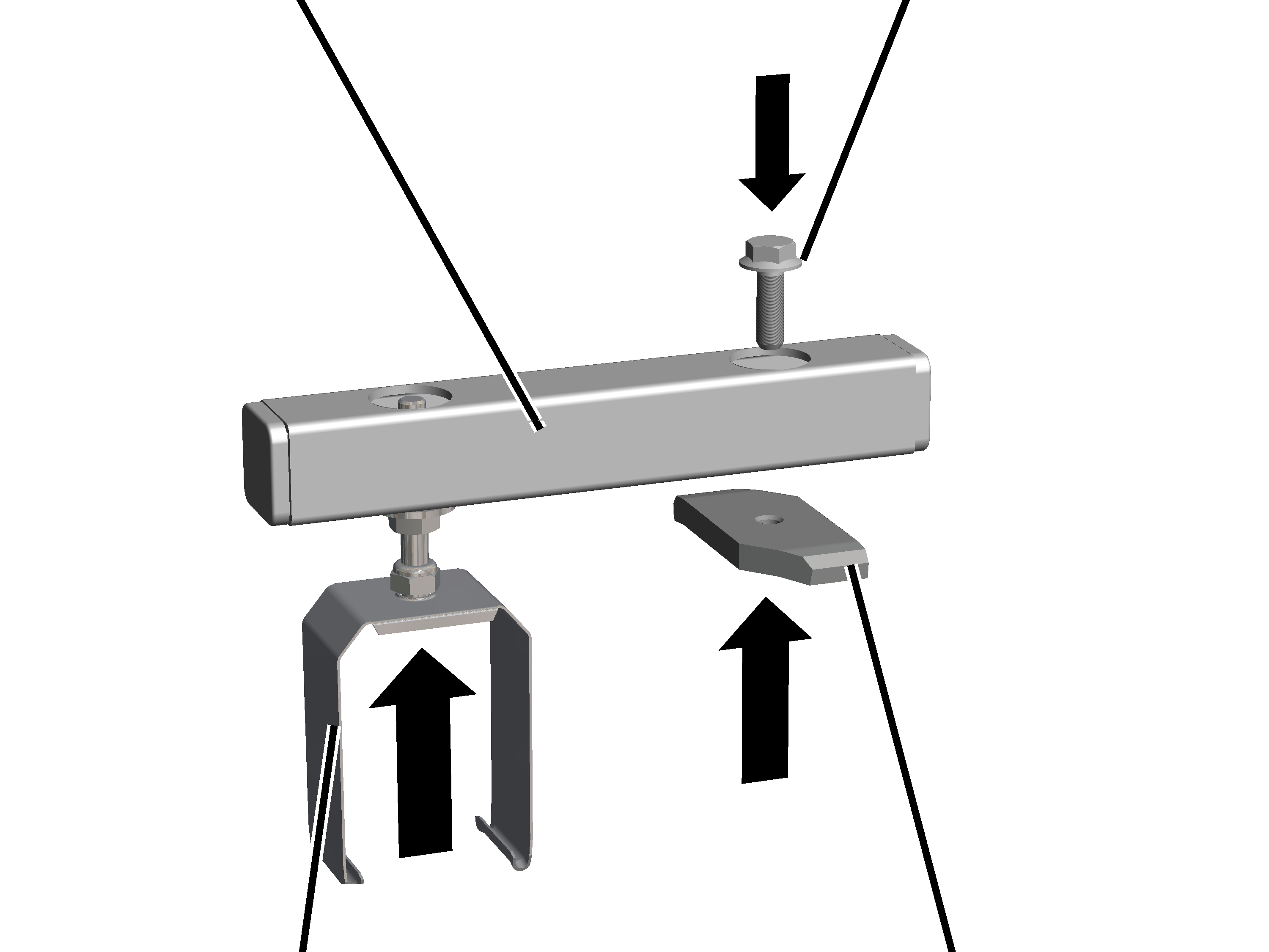
The conductor system KBH is installed on the profile head of the HB profile rail with fasteners.
|
|
Where and at what intervals the brackets are mounted is specified in the planning documents. |
On each support:
|
Support |
Rib screw M8x25 |
|
| |
|
Suspension |
Head nut |
Insert the suspension on one side of the support from below and bolt
it tight.
Insert an M8x25 rib screw on the other side of the support from
above.
Screw the head nut (2x) onto the rib screw from below.
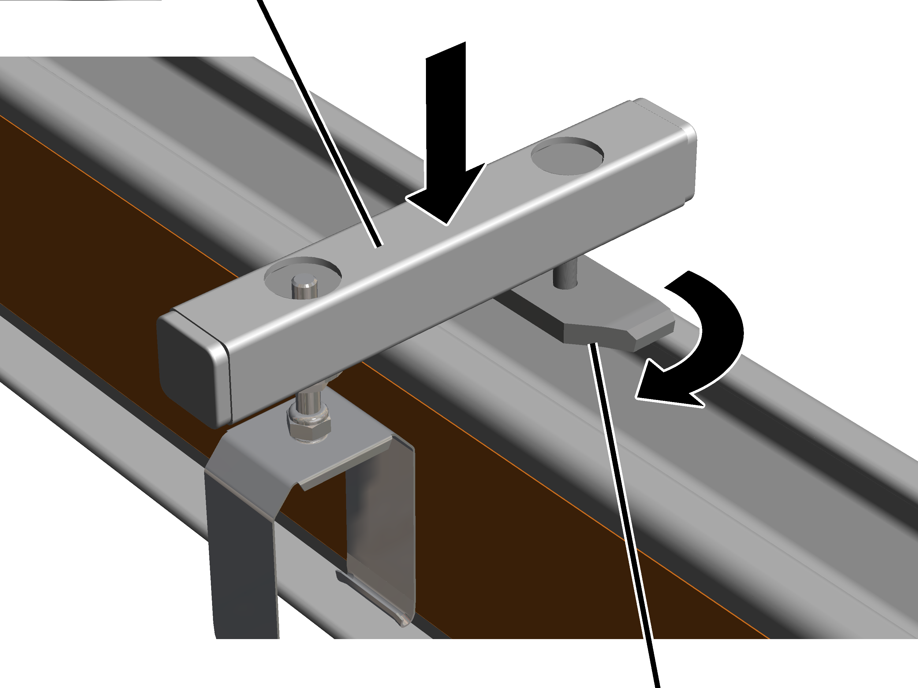
|
Support |
|
|
| |
|
|
Head nut |
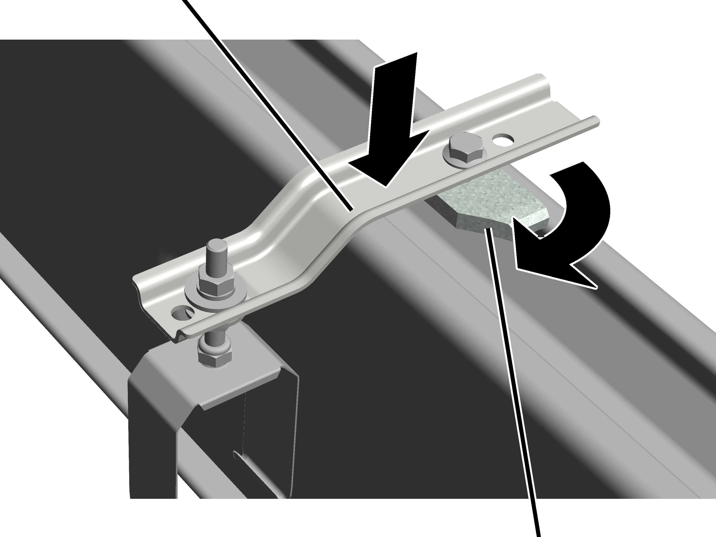
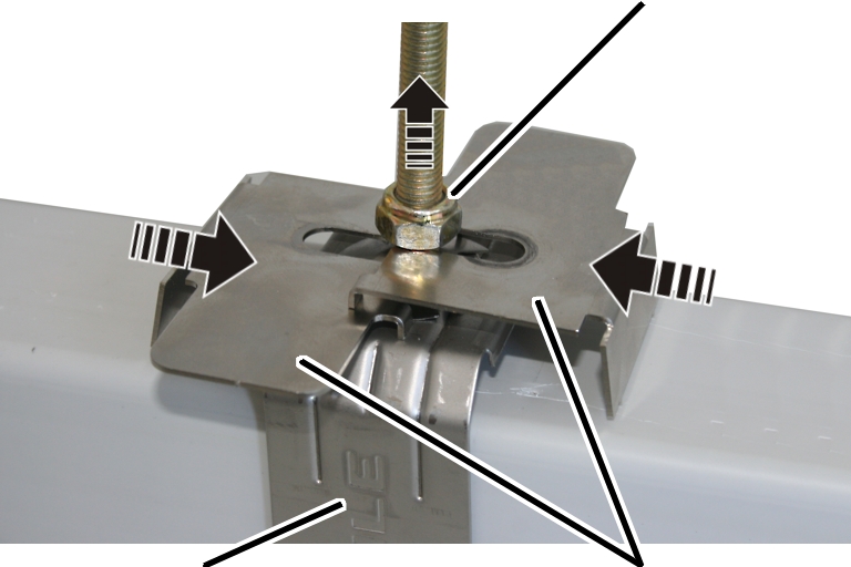
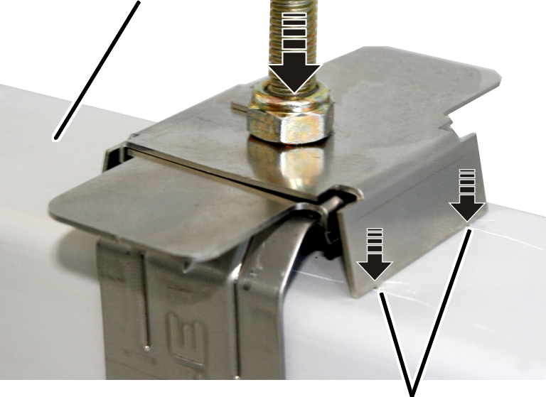
 Turn the head nut in the longitudinal direction and lay the support
on the profile head from above.
Turn the head nut in the longitudinal direction and lay the support
on the profile head from above.
● The head nut extends into the profile head.
Screw the rib screw tight. 30 Nm.
● The head nut turns during fixing in the crosswise direction and is clamped tight in the profile head.
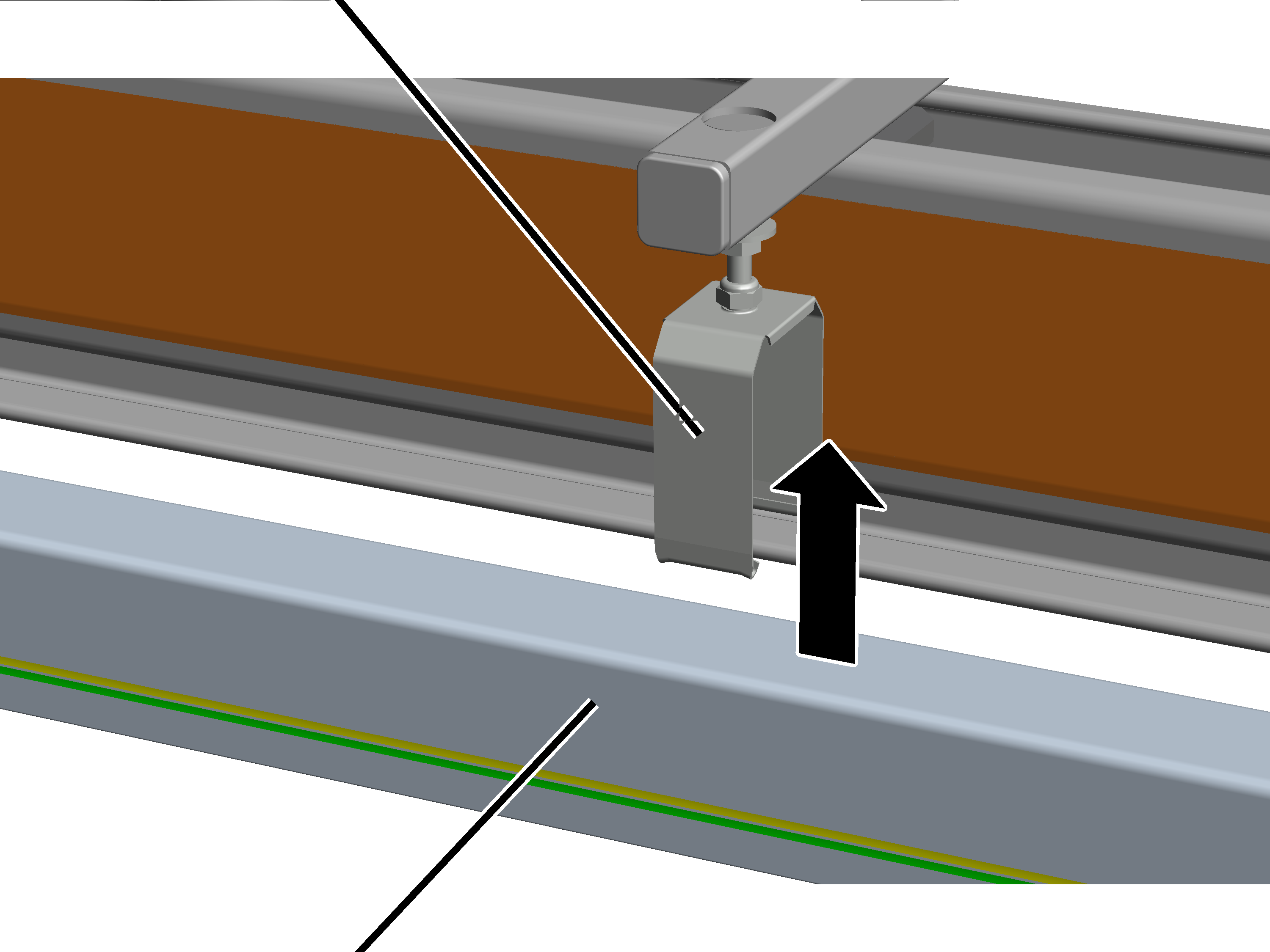
For every section:
|
Suspension |
|
|
| |
|
Section |
|
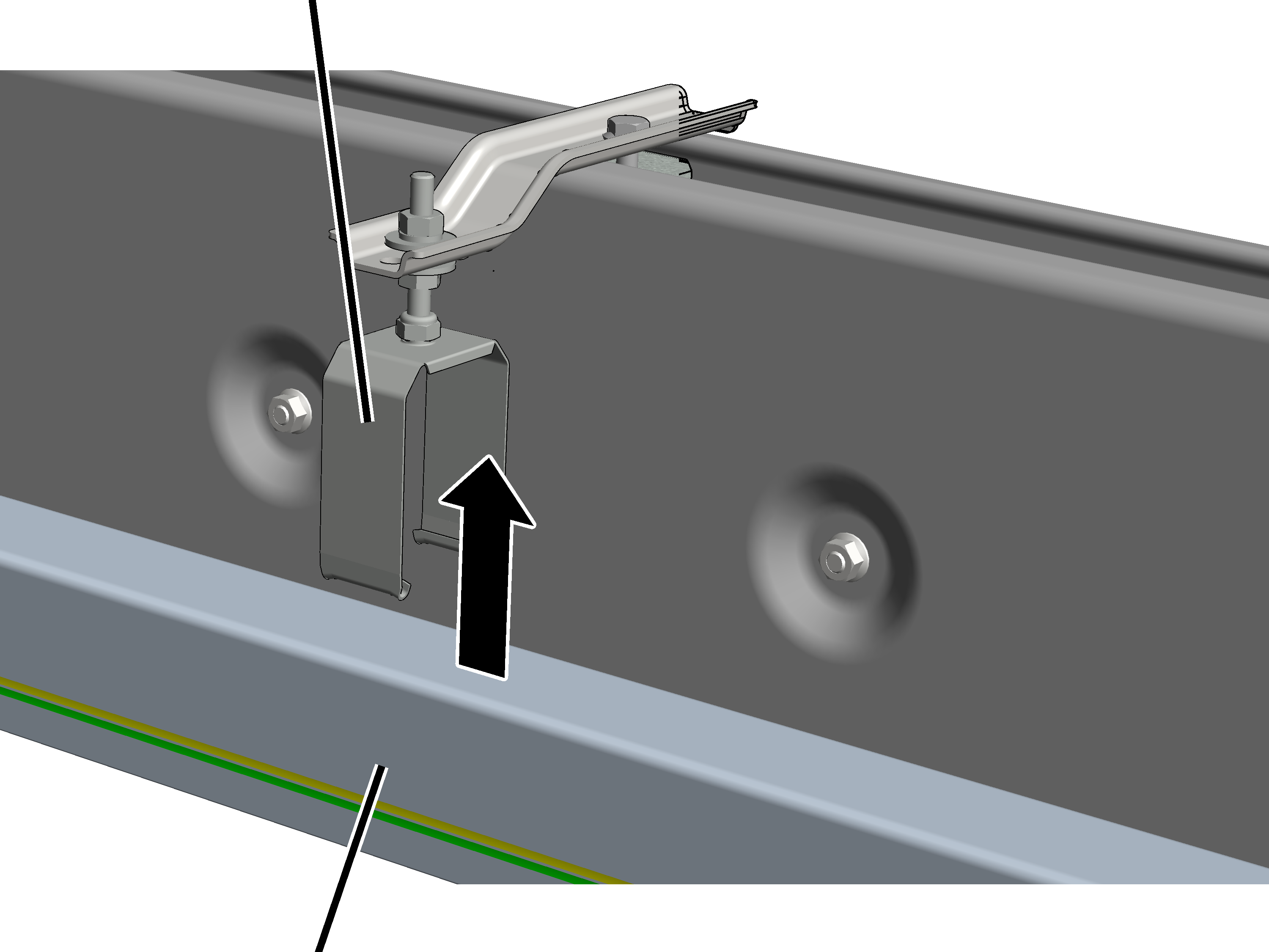
 Insert the section into the suspension from below.
Hook the suspension with the hook into the conductor system from
below.
The conductor system KBH is installed on the profile head of the HB profile rail with fasteners.
|
|
Where and at what intervals the brackets are mounted is specified in the planning documents. |
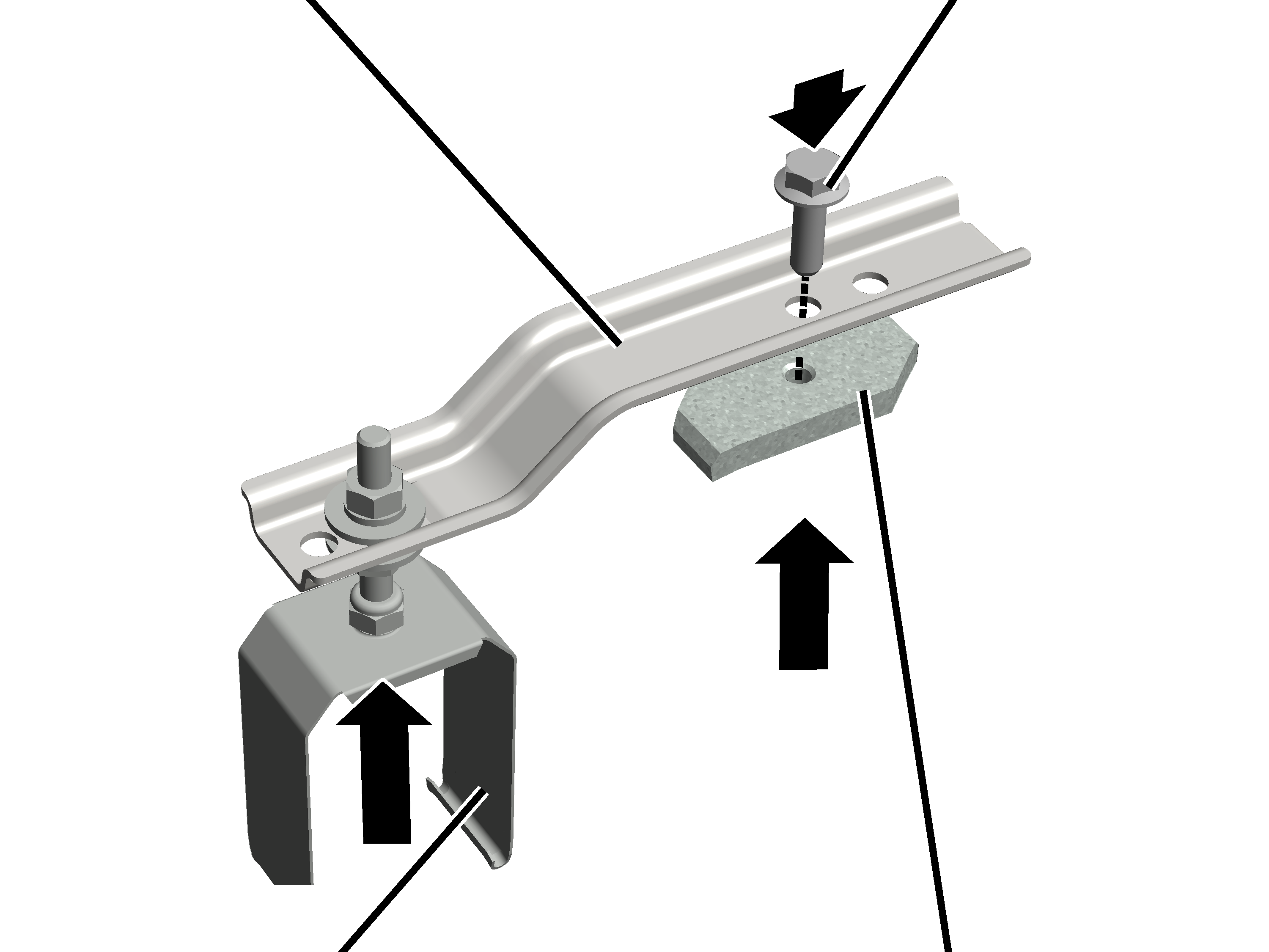
On each support:
|
Support |
Rib screw M8x25 |
|
| |
|
Suspension |
Head nut |
 Insert the suspension on the lowered side of the support from below
into the inside hole and bolt it tight.
Insert the suspension on the lowered side of the support from below
into the inside hole and bolt it tight.
Insert an M8x25 rib screw on the raised side of the support from
above into the inside hole.
Screw the head nut (2x) onto the rib screw from below.
|
Support |
|
|
| |
|
|
Head nut |
Turn the head nut in the longitudinal direction and lay the support
on the profile head from above.
● The head nut extends into the profile head.
Screw the rib screw tight. 30 Nm.
● The head nut turns during fixing in the crosswise direction and is clamped tight in the profile head.
For every section:
|
Suspension |
|
|
| |
|
Section |
|
Insert the section into the suspension from below.
Hook the suspension with the hook into the conductor system from
below.
Check whether the section hangs in the suspension on both sides and
can slide in the direction of the HB profile rail.
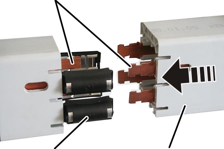
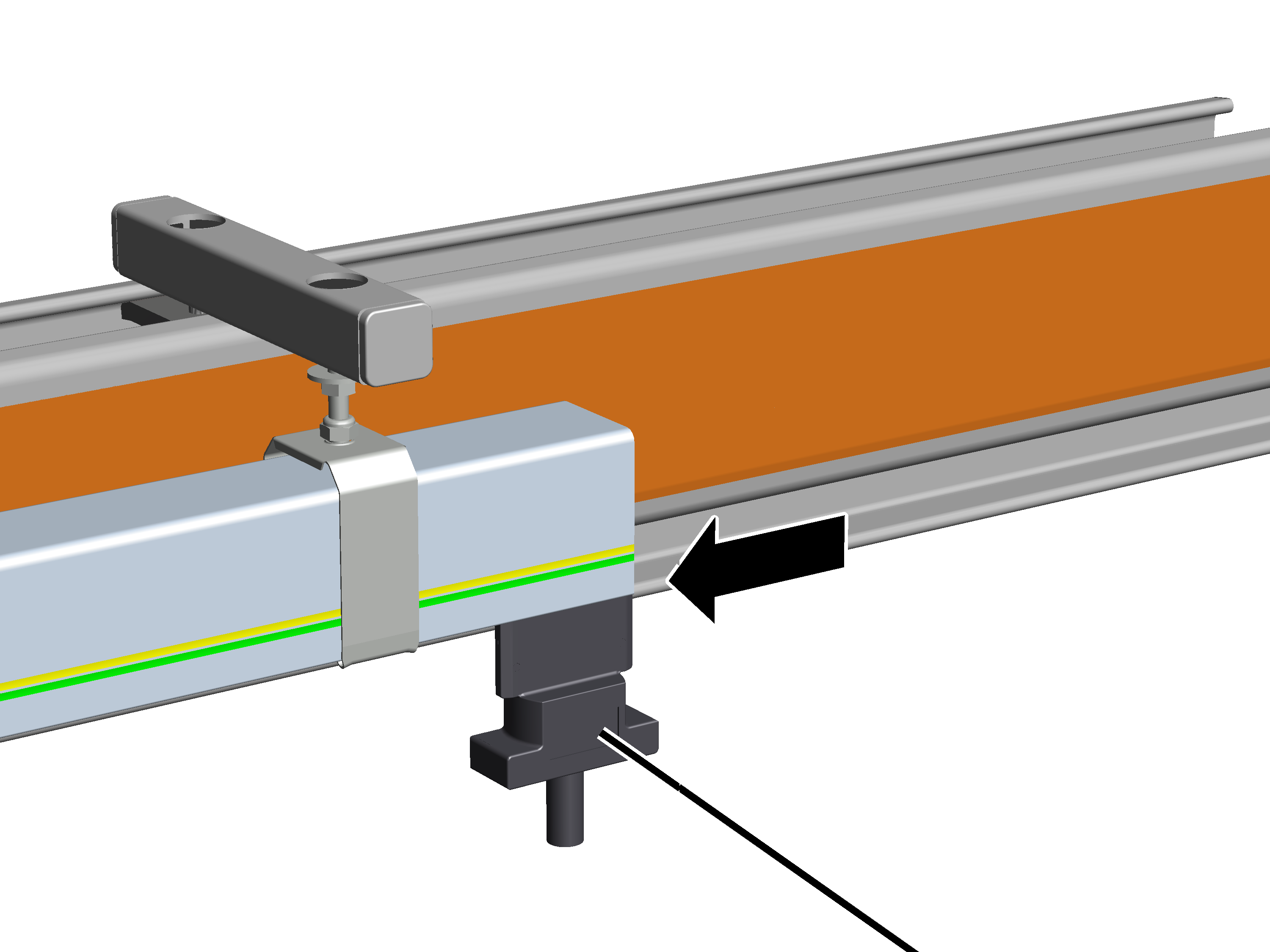
The sections are electrically connected with one another by means of connectors.
At every joint:
|
Rail |
|
|
| |
|
Connector |
Section |
● On the right end of a section there is a connector inserted on every rail.
● On the left end of a section, the rails are shaped so that they cannot slip into the conductor system.
Align the rails so that they can be inserted in the connectors.
Place a wood block between the rails at the end of a section and use
a hammer to strike the section against the previous one.
● The rail slides into the connector.
Check all rails to ensure the connectors have securely latched.
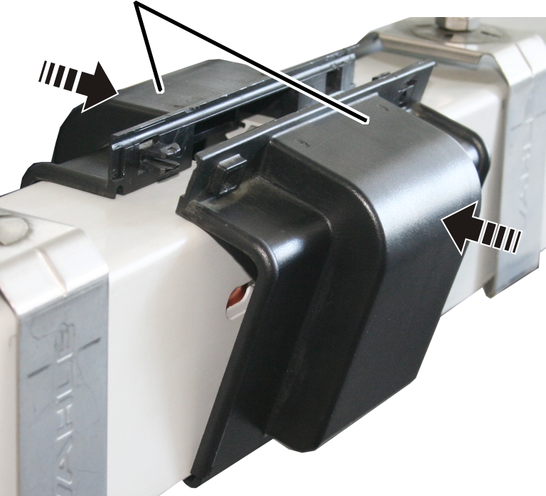
A joint cover connects the sections with each other mechanically and protects against contact with the rails.
At every joint:
|
Joint cover |
|
|
| |
Insert joint cover (2x) bottom in the conductor system.
Press joint together at top and latch it.
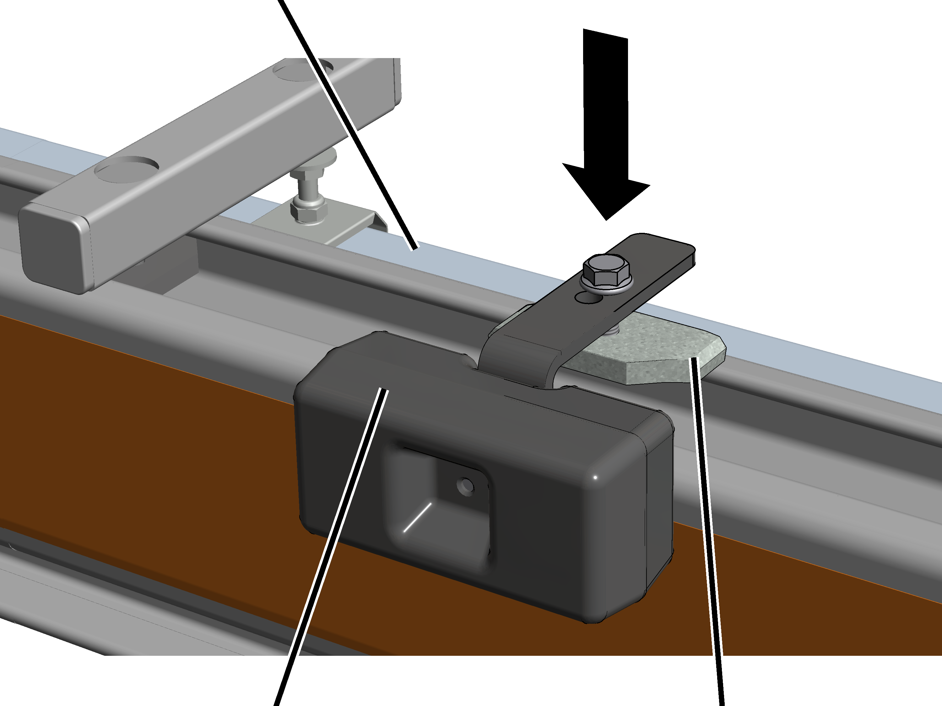
One of the sections is now fixed to the suspension. The other sections remain loosely latched. This allows the entire conductor system to freely expand or contract when temperatures change. However, due to the one fixed section, the entire conductor system cannot slide into the rest of the sliding suspension.
The section to be fixed should lie about in the middle (within the span of the conductor system).
Centred within the span of the conductor system:
|
|
Self-locking nut |
|
| |
|
Suspension |
Fixing clamp |
Release the upper self-locking nut.
Move the fixing clamps (2x) from the right and left between the
self-locking nut and the suspension.
Push the fixing clamps together so that they hook into each
other.
|
Conductor system |
|
|
| |
|
|
Claws on the fixing clamp |
Tighten the self-locking nut. 7 Nm.
● The fixing clamps fix the section by holding it in their claws.
● Check whether the conductor system can no longer slide.
This section only applies if the KBH conductor system is mounted on the HB crane EHB or EHB-I. For all other HB cranes and on the HB crane runway, this section can be skipped over.
The counterweights ensure that the HB profile rails are suspended straight. Without the counterweights, the HB profile rails would sag on the side with the KBH conductor system.
|
|
Where and at what intervals the counterweights are installed is specified in the planning documents. |
On the opposite side of the conductor system:
|
Conductor system KBH |
|
|
| |
|
Counterweight |
Head nut |
Insert the counterweight in the profile head from above.
Turn the head nut in the longitudinal direction.
● The head nut extends into the profile head.
Tighten the rib screws. 30 Nm
● The head nut turns during fixing in the crosswise direction and is clamped tight in the profile head.
|
| |
|
|
Current collector |
Slide the current collector into the conductor system.
Slide the current collector over the entire length of the conductor
system to test it.
The current collector must move smoothly and not get caught, particularly at the joints.
On the trolley:
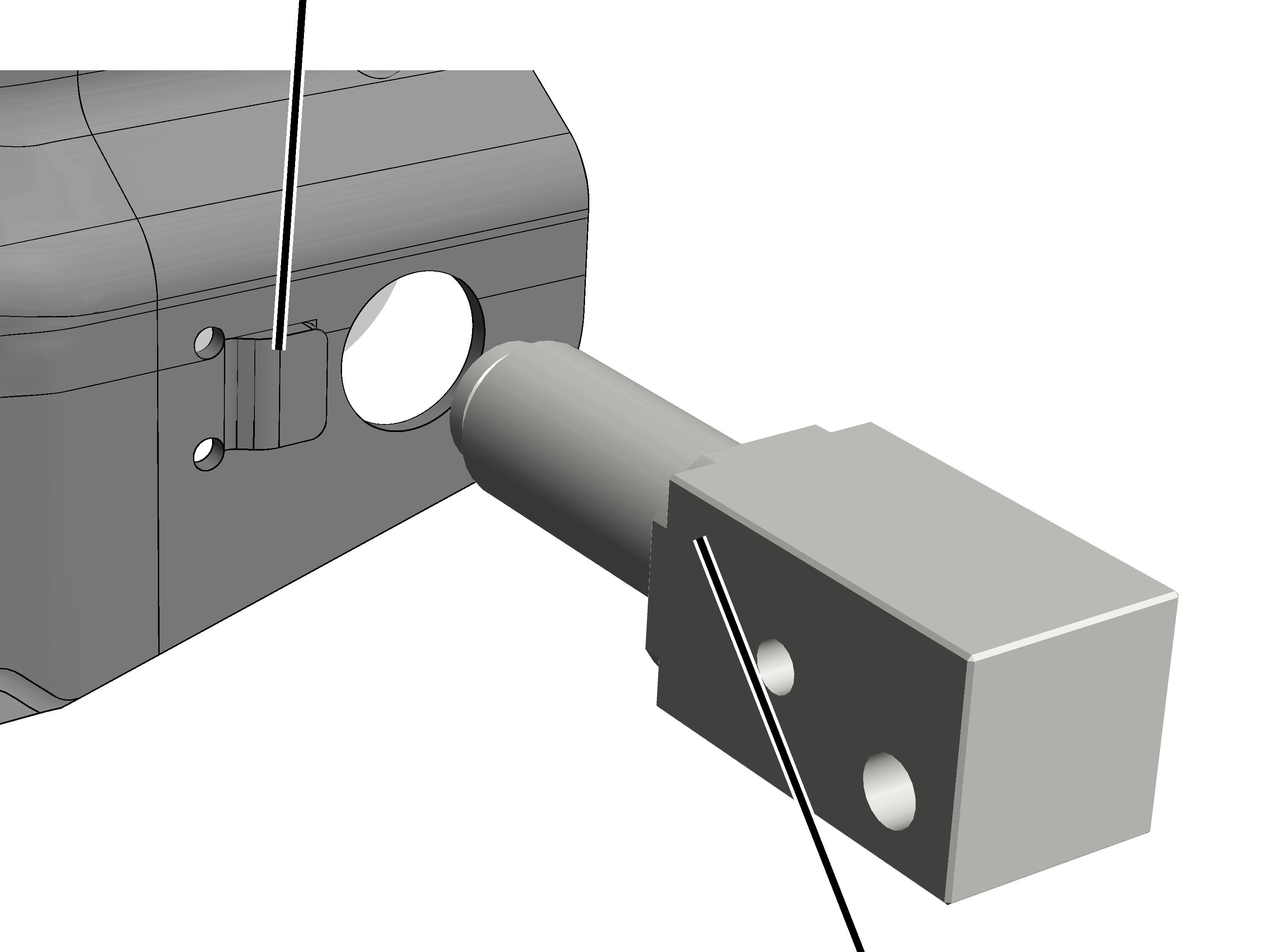
The carrier shaft can also be installed in drilled holes on which other add-on components (e.g. anti-collision device or HBF drive) have already been installed. In this case, remove the installed bolt and mount the add-on component with the carrier shaft.
This work step is only applicable if the trolley has a protruding nose next to the drilled hole as an integrated anti-rotation device.
|
Integrated anti-rotation device |
|
|
| |
|
|
Carrier shaft |
Push the carrier shaft directly into the drilled hole on the
trolley.
Do not use the included separate anti-rotation device!
● The carrier shaft is secured on the trolley by means of an integrated anti-rotation device and cannot turn.
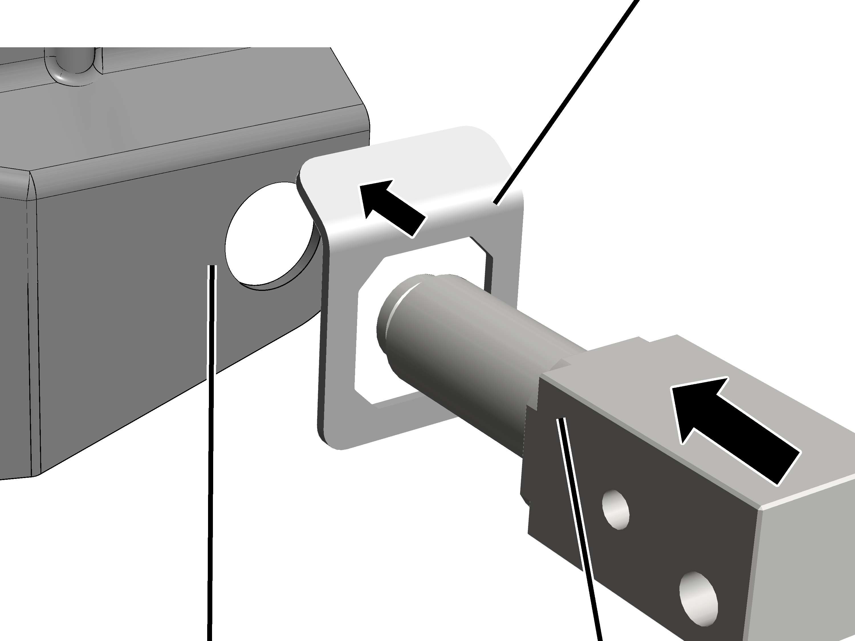
This work step is only applicable if the trolley does not have an integrated anti-rotation device.
|
|
Separate anti-rotation device |
|
| |
|
Trolley without anti-rotation device |
Carrier shaft |
Place the separate anti-rotation device over the drilled hole on the
trolley.
Push the carrier shaft through the separate anti-rotation device into
the drilled hole on the trolley.
● The carrier shaft is secured on the trolley by means of the separate anti-rotation device and cannot turn.
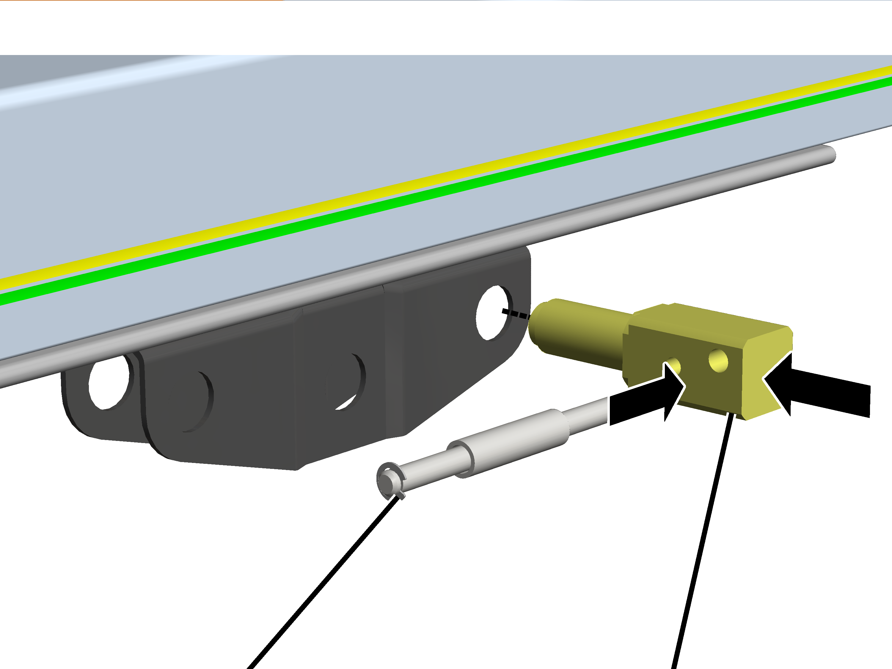
|
| |
|
Bolt |
Carrier shaft |
Push the carrier shaft through the trolley.
How the carrier shaft is inserted (outer hole up or down) makes no difference.
Insert the SL safety clip.
Insert bolt with bush through the outer drilled hole in the carrier
shaft.
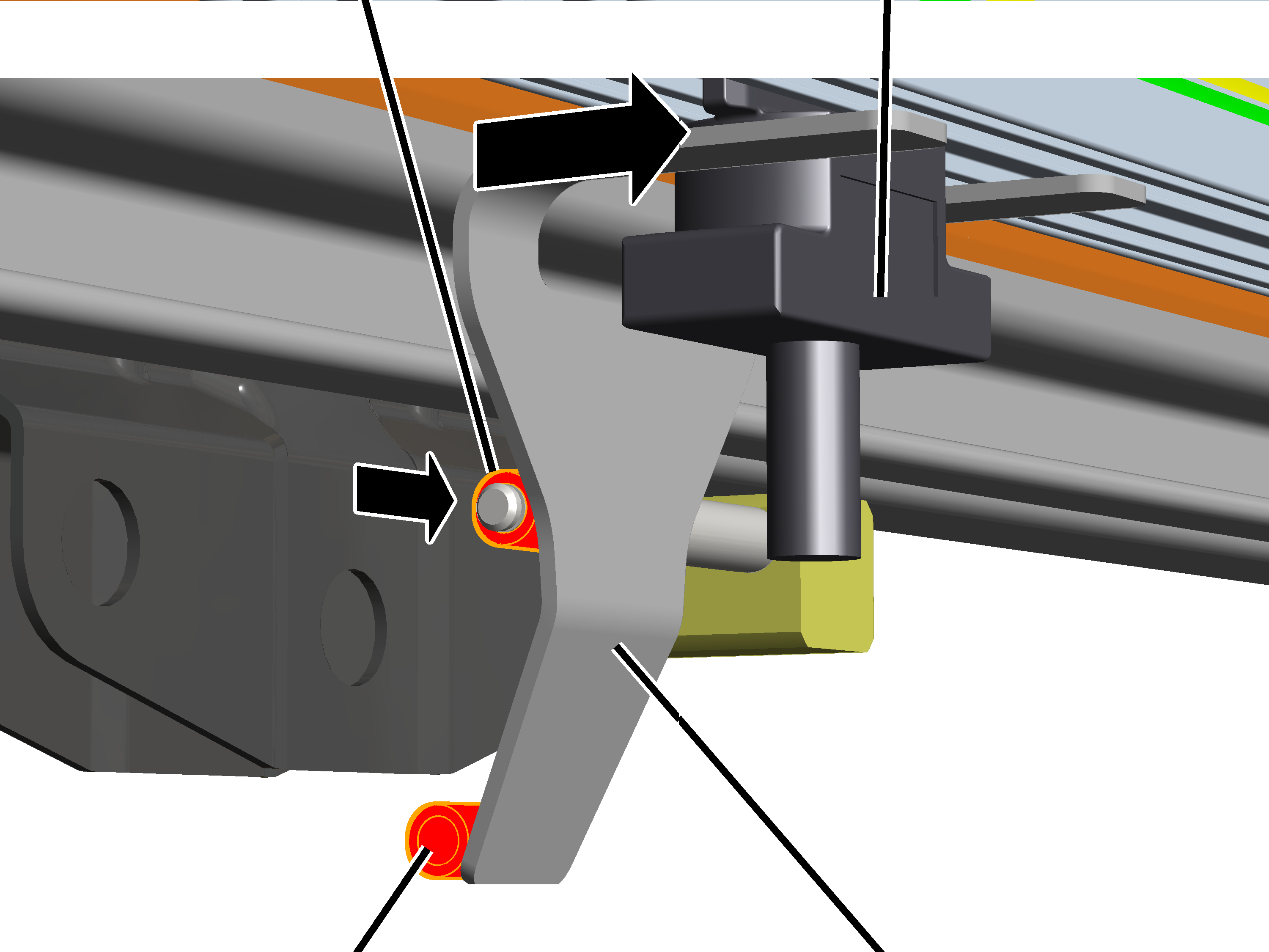
|
Top tube on carrying fork |
Current collector |
|
| |
|
Bottom tube on carrying fork |
Carrying fork |
Insert the carrying fork on the current collector.
Push the carrying fork onto the bolt on the carrier shaft.
─ For HB150 and HB190: use top tube on the carrying fork.
─ For HB240: use lower tube on the carrying fork
Secure bolt with SL safety clip.
|
|
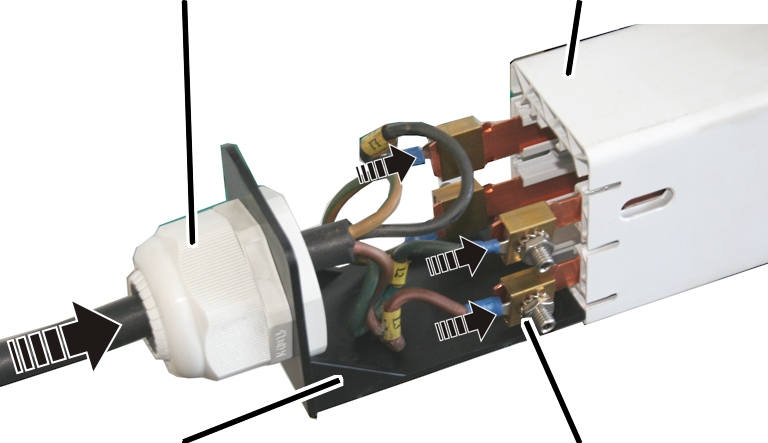
What position is intended for the feed unit is specified in the planning documents. |
|
|
The figures show the installation of a steel HB profile rail of size HB150S. The installation of larger or smaller HB profile rails or aluminium HB profile rails does not differ significantly from this. |
|
Cable fitting |
Conductor system |
|
| |
|
Base plate |
Screw terminal |
Guide the connection cable through the cable fitting of the base
plate.
Attach the connection cable to the rail with the screw terminals.
Push the base plate at the bottom into the conductor system.
If needed, the cable fitting can also be mounted so that it protrudes downward from the base plate. Depending on the particular fitting situation and spatial conditions on-site, this may enable improved guiding of the cable.
|
|
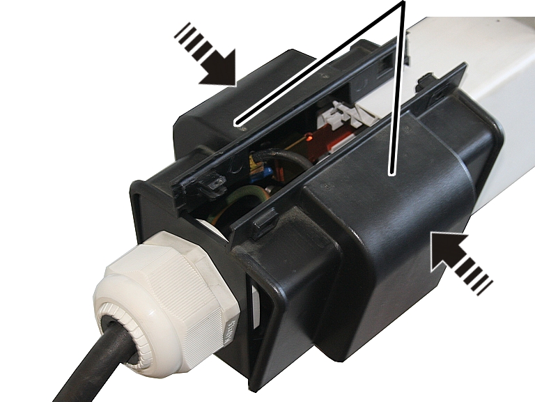
Retaining cap |
|
| |
Insert the retaining cap (2x) bottom in the conductor system and the
base plate.
Press the retaining cap together at the top and latch it.
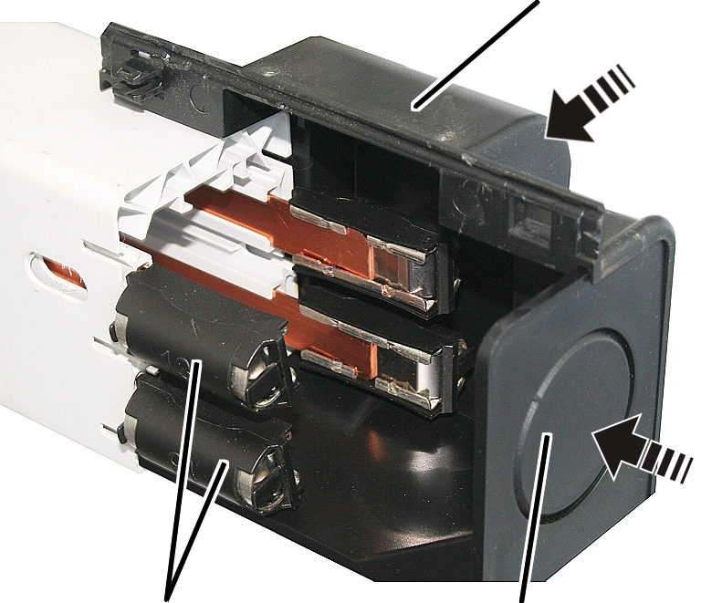
On the opposite end of the feed unit:
|
|
Retaining cap |
|
| |
|
Connector |
Base plate |
Insert the base plate in the conductor system.
Insert the retaining cap (2x) bottom in the conductor system and the
base plate.
Press the retaining cap together at the top and latch it.
● The rails and the connectors are protected against contact and dirt.
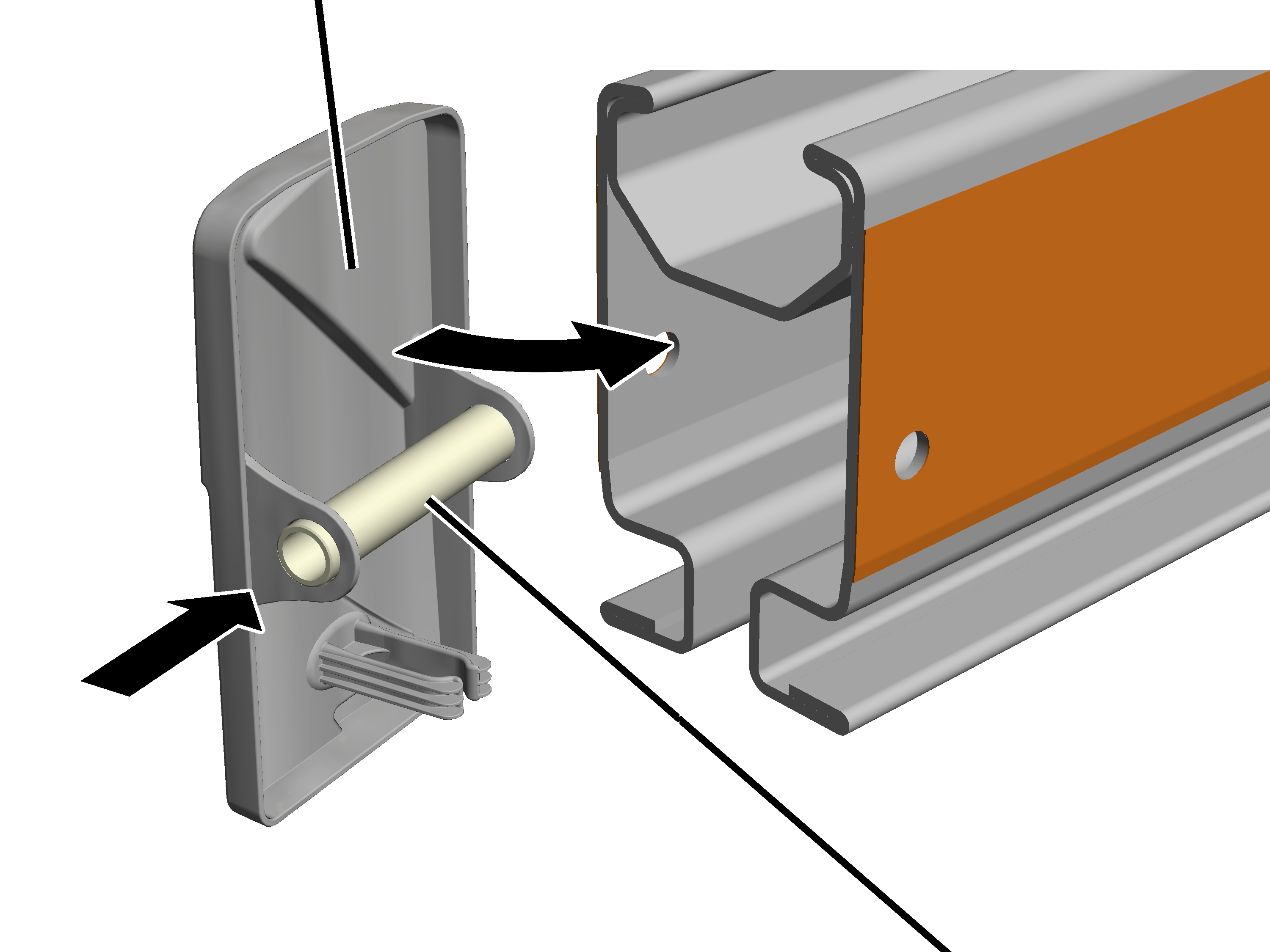
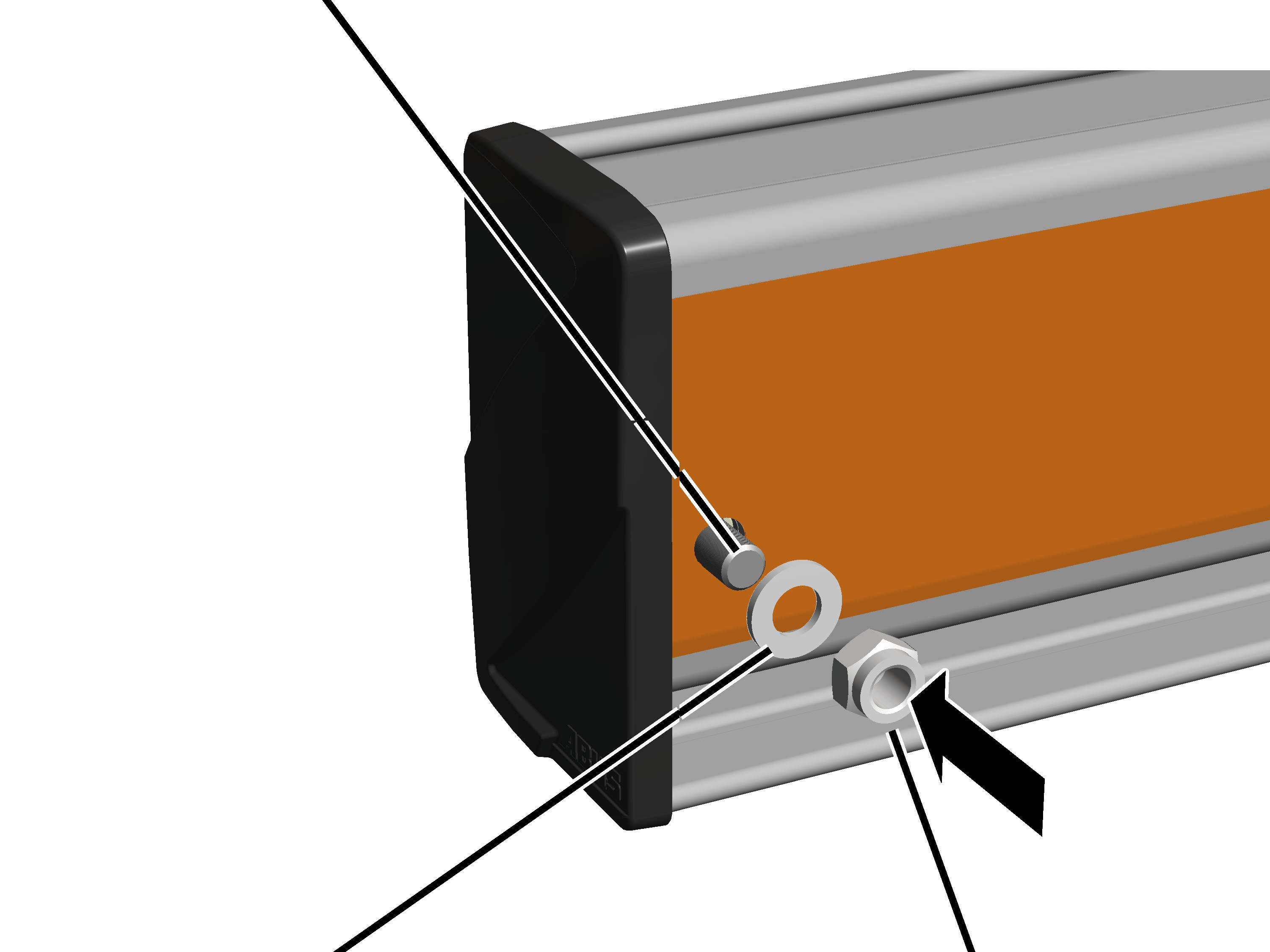
Every HB profile rail must be fitted with end caps on the profile ends. These prevent dirt from penetrating the HB profile rail and also serve as an end stopper to prevent the HB crane or trolley from falling out of the HB profile rail.
On the front and back of all HB profile rails:
|
End cap |
|
|
| |
|
|
Spacer sleeve |
Push the spacer sleeve into the end cap.
Only with HB240: use the spacer sleeve with black coating. It is slightly longer than the spacer sleeve with silver or yellow coating.
Put on the end cap.
If necessary, widen the HB profile rail slightly to enable insertion of the spacer sleeve.
|
Hexagon head screw |
|
|
| |
|
Washer |
Self-locking M12 nut |
Insert a hexagon head screw through the HB profile rail and the
spacer sleeve.
|
Size |
Hexagon head screw |
|
HB110 |
M12x85 |
|
HB150 |
M12x110 |
|
HB190 |
M12x110 |
|
HB240 |
M12x110 |
Insert washer, screw on the self-locking M12 nut. 80 Nm.