Installing the
travel stop
The cable marshalling point (the profile end on which the
festoon cable system is pushed together by the trolley) must be installed with a
travel stop. This prevents the trolley from running to the very end of the HB
profile rail and impacting the cable marshalling point with the cable
sliders.
|

|
The position for installing the travel stop is
specified in the planning documents. |
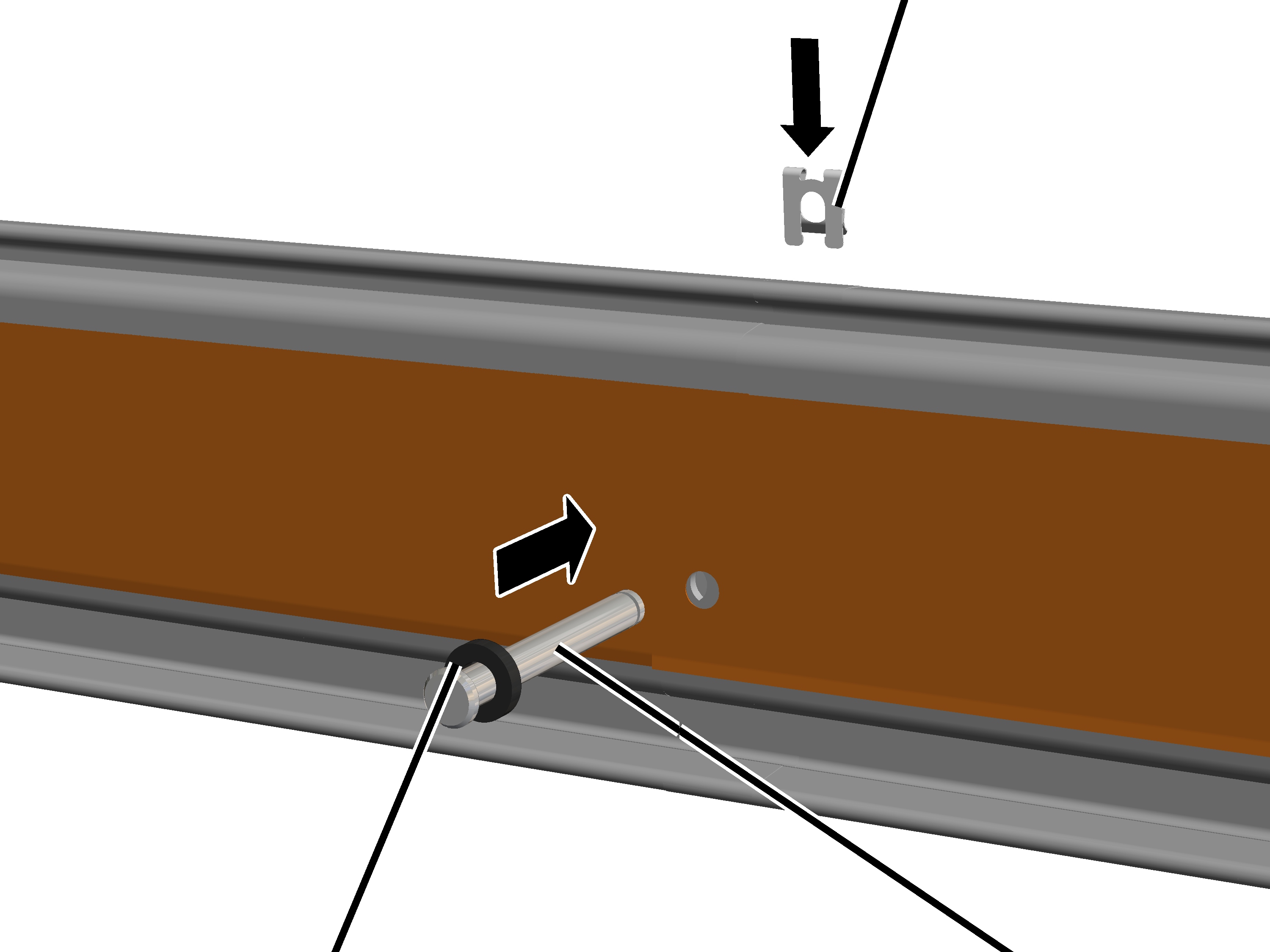
Installing the travel stop at the cable marshalling point:
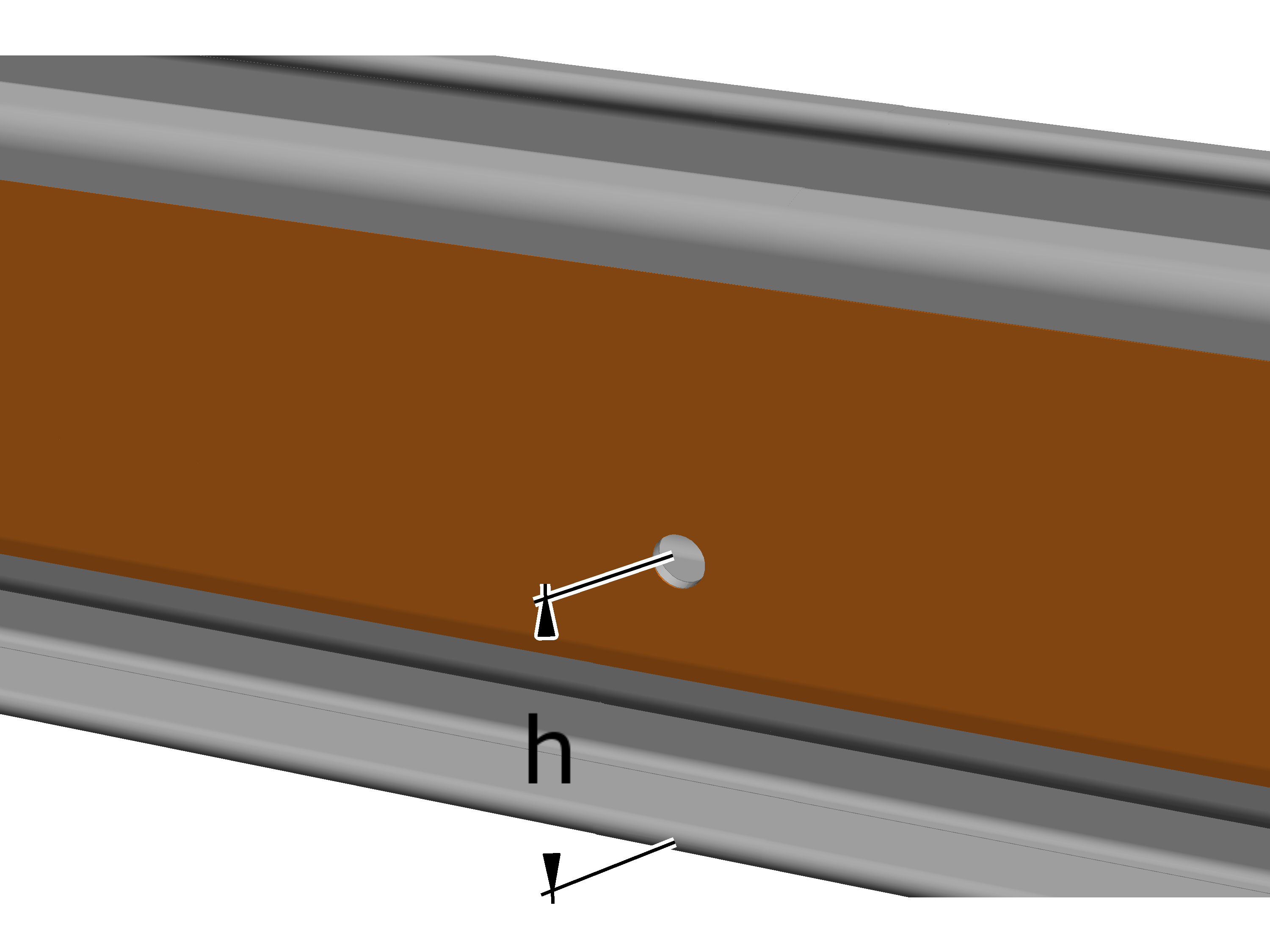
 Drill a hole in the profile rail section on both sides for the travel
stop:
Drill a hole in the profile rail section on both sides for the travel
stop:
─ Distance
from the profile end: as calculated or taken from the planning documents.
─ Diameter
12 mm.
─ Distance
to lower edge
|
Size |
Distance |
|
HB110 |
53 mm |
|
HB150 |
73 mm |
|
HB190 |
73 mm |
|
HB240 |
73 mm |
─ If the
travel stop lies in the area of a profile joint: drill through both the profile
rail section as well as the clamping plates.
 Deburr the drilled holes.
Thoroughly remove any saw or drill shavings.
Otherwise the shavings can clog the castors of the trolleys and
impair their running.
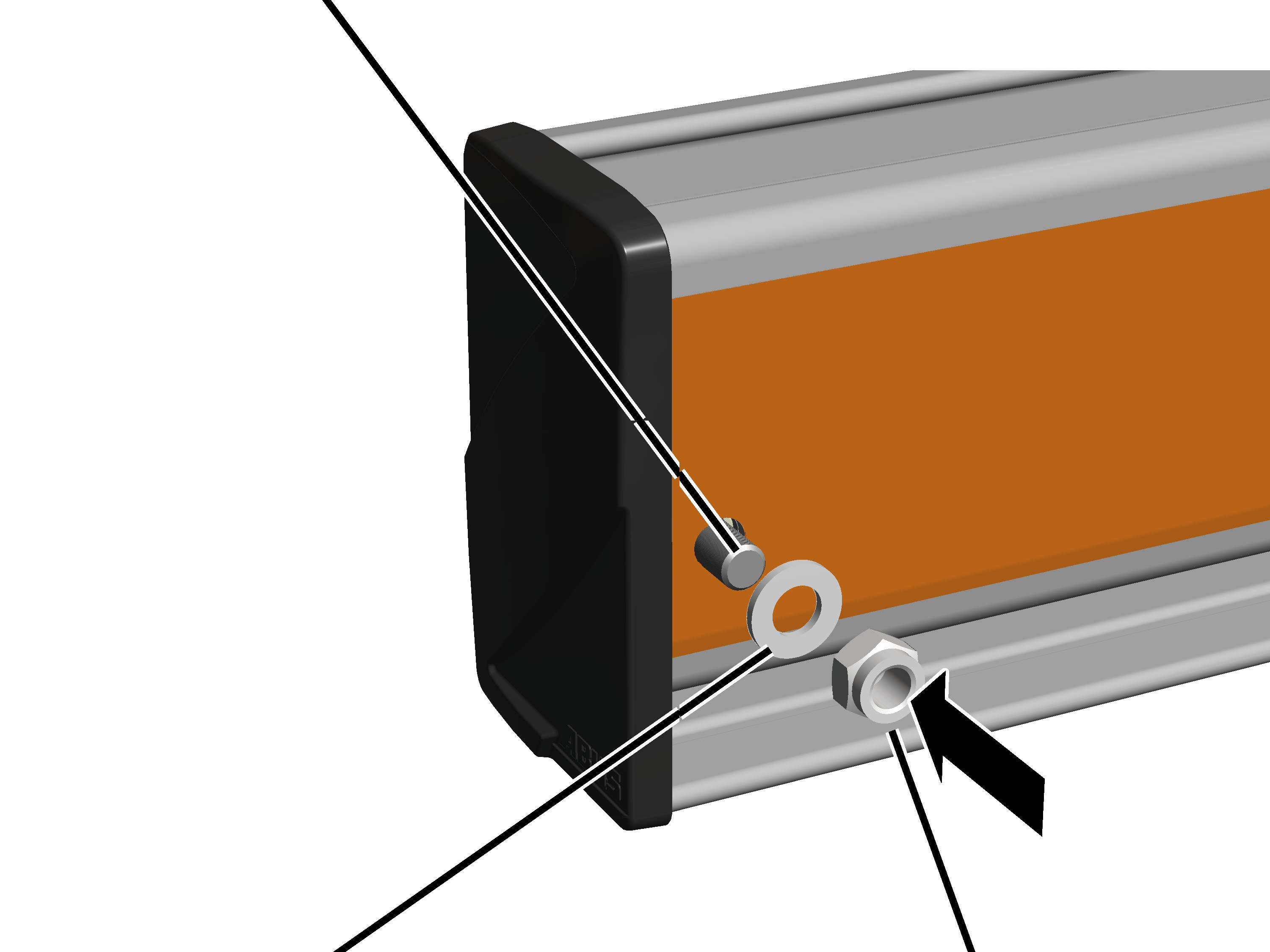
|
|
SL
safety clip |
|
|
|
Spacer
disc |
Bolt |
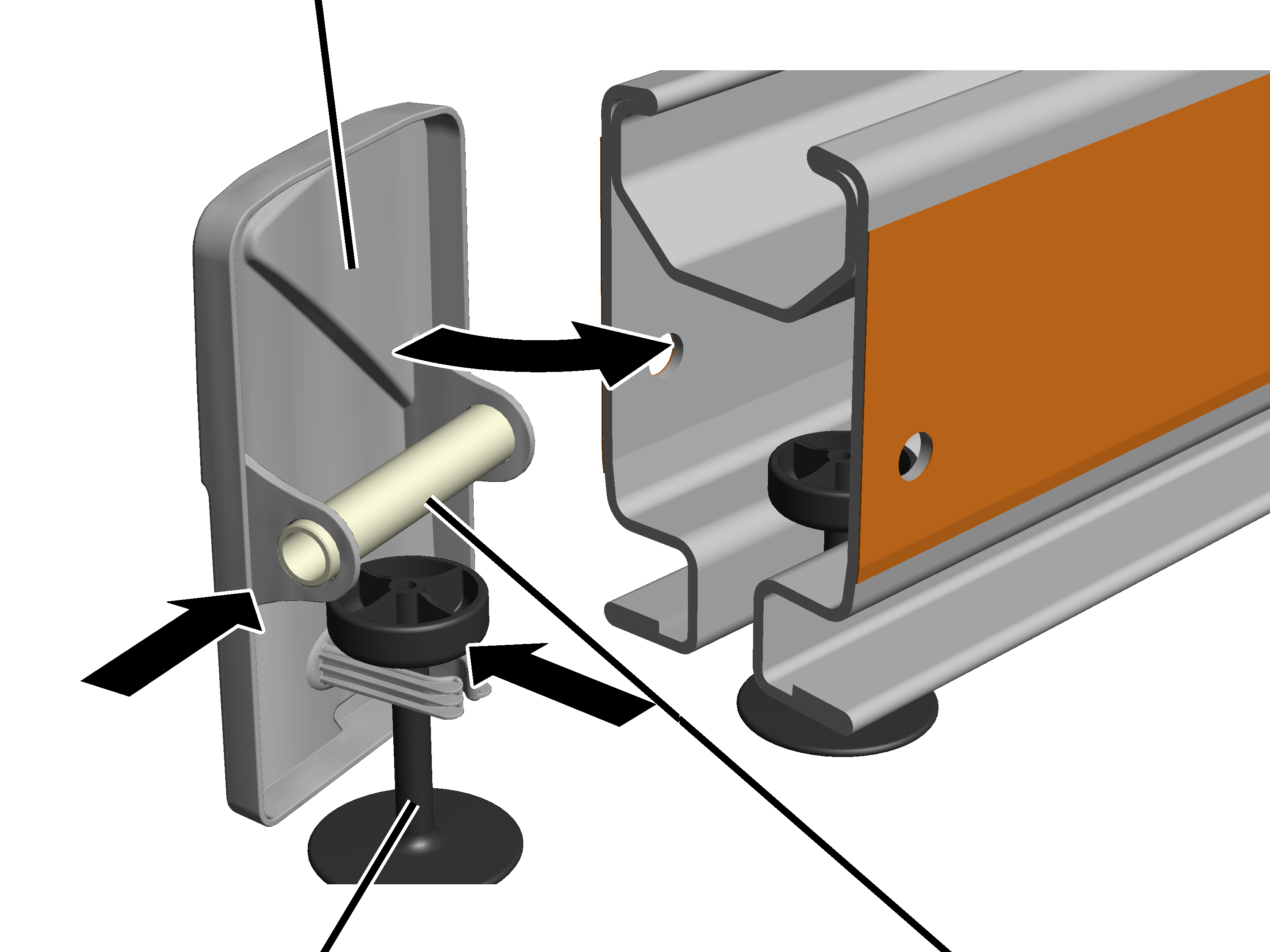
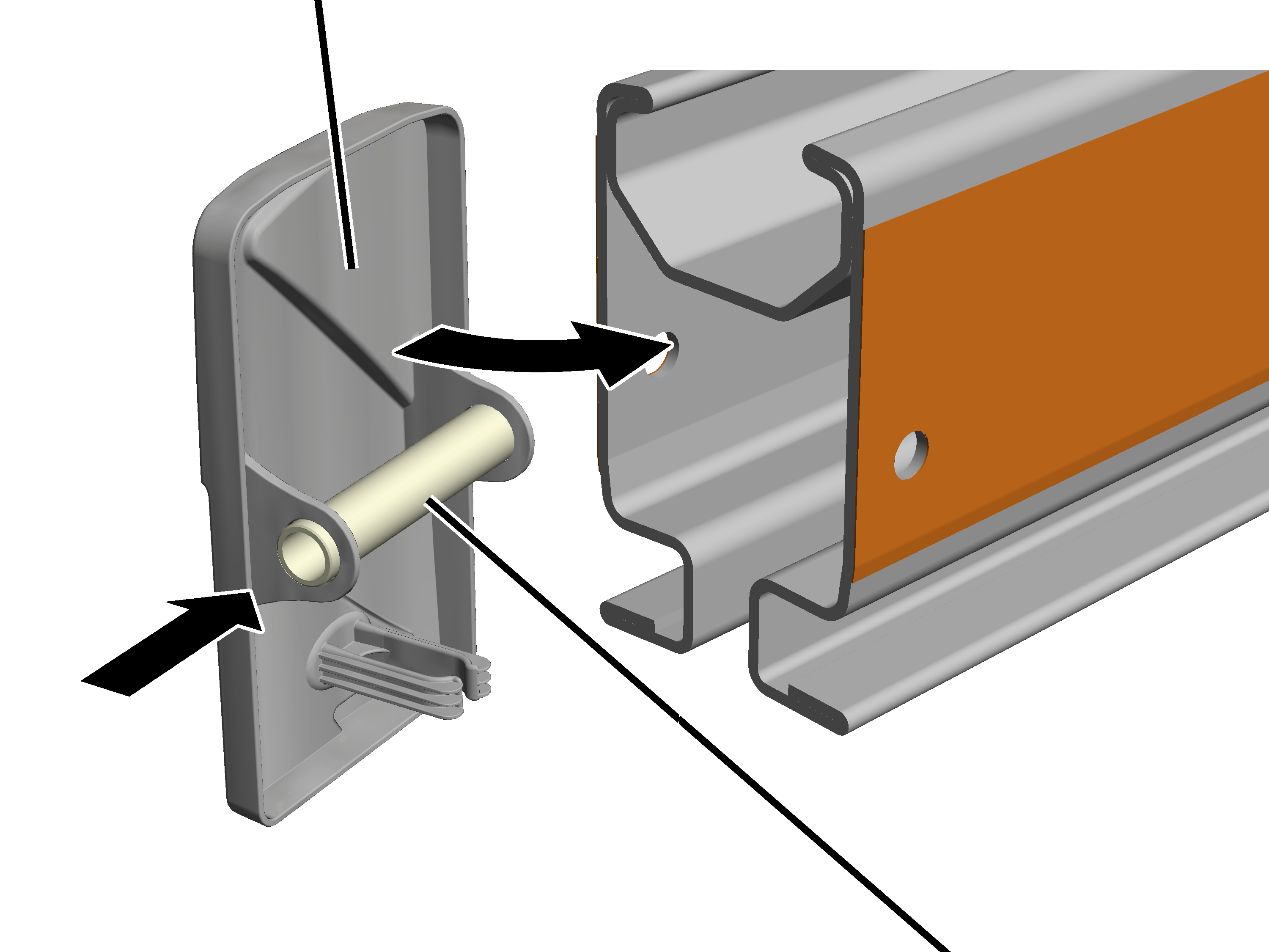
If the travel stop lies in the area of a profile joint: insert the
bolt through the HB profile rail.
If the travel stop lies on a free profile rail: place a spacer on the
bolt and insert the bolt through the HB profile rail.
Secure bolt with SL safety clip.
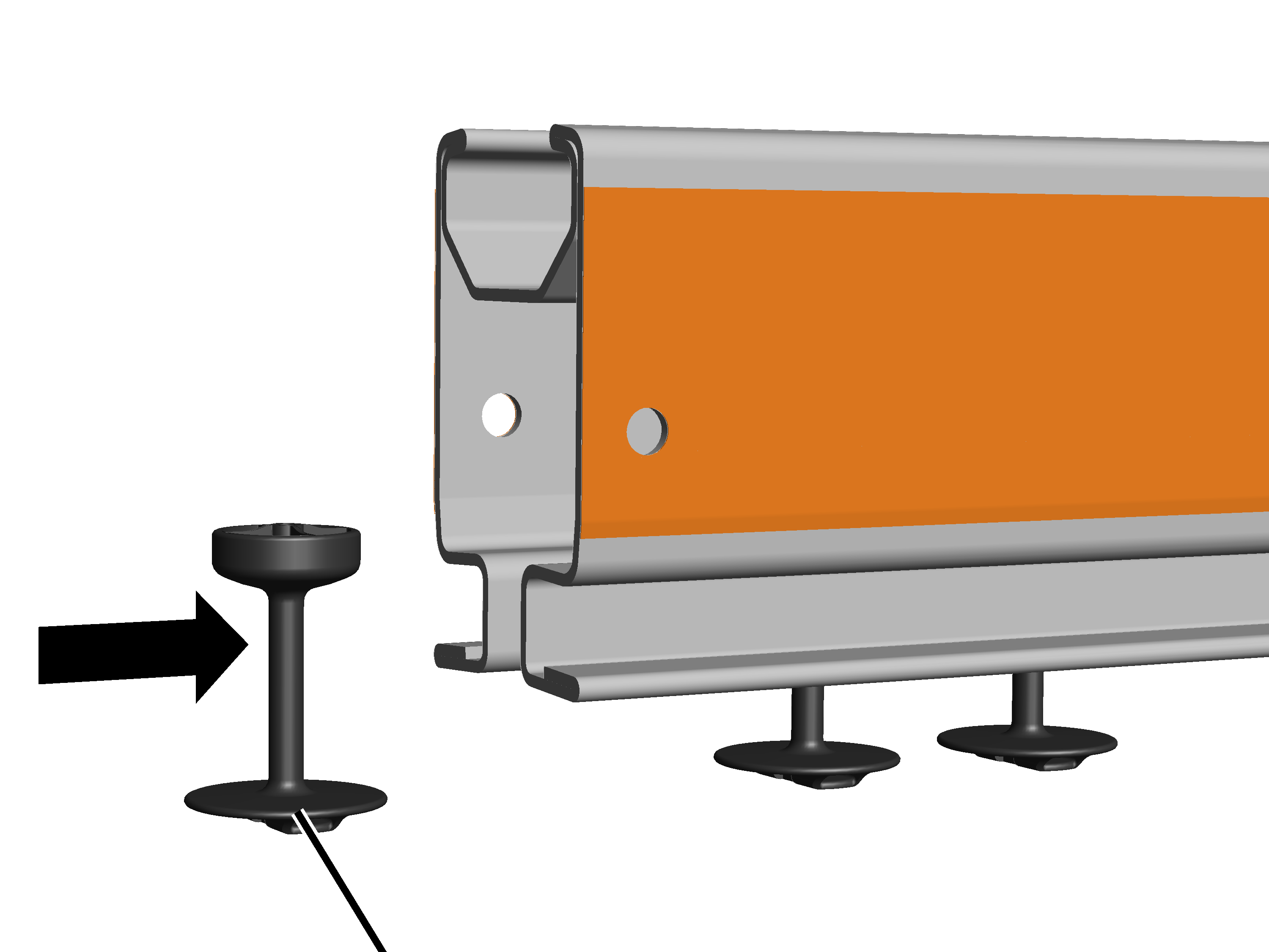
Inserting cable
sliders
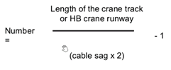
Calculate the number of cable sliders:
Read off the cable sag from the crane drawing.
Calculate and round off the number of cable sliders.
Insert cable sliders:
|
|
|
Cable
slider |
|
Insert the corresponding number of cable sliders.
Installing the
festoon cable system on the trolley
On the trolley lying in the direction of the power supply:
|
Cable
support |
Support |
|

|
|
Hexagonal nuts |
Rib
screw |
Screw the bracket onto the trolley with the M8x25 rib screw.
20 Nm.
Press the festoon cable system with cable support against the
bracket. Screw tight with M6x40 hexagon head screws (2x) and M6 hexagonal nuts
(2x).
Lock with M6 hexagonal nuts (2x).
Fastening the
festoon cable system on cable sliders
|
Cable
sag x 2 |
|
|
|
|
|
Cable
sag |
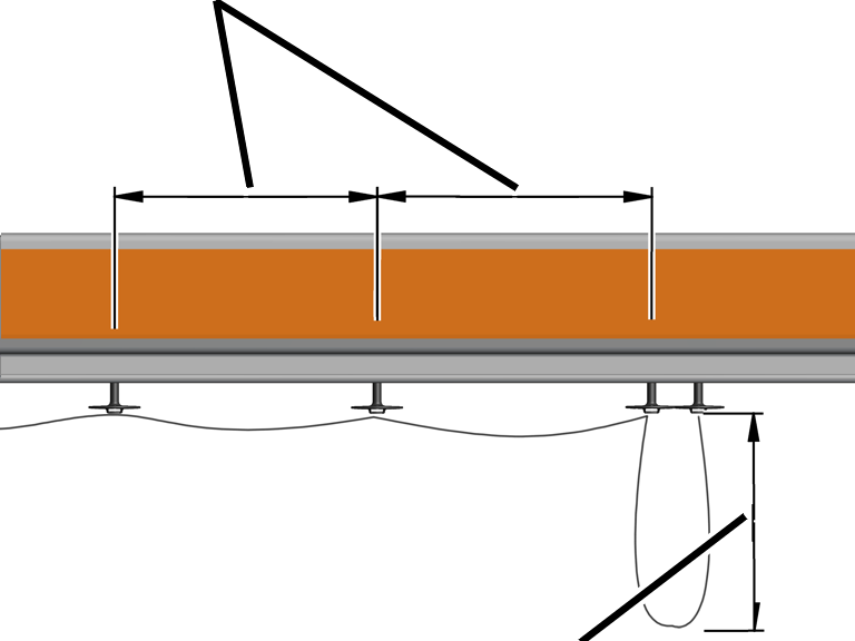
Lay the festoon cable system from the end of the HB profile rail and
fasten loosely at first with cable clips on the cable sliders.
For narrow, individual flat
cables, push the cable clips in the narrow opening on the cable slider. For wide
or multiple cables, use the wide opening.
Position the cable sliders in such a way that two cable sliders are
twice the cable sag away from one another.
The cable sag (usually 800 m) is specified on the crane
drawing.
Depending on the total length of the flat cable, the cable
sliders can also lie closer together. The spacing between all cable sliders
should nevertheless remain the same.
Tighten the cable clips.
Installing the
festoon cable system on the profile end
Every HB profile rail must
be fitted with end caps on the profile ends. These prevent dirt from penetrating
the HB profile rail and also serve as an end stopper to prevent the HB crane or
trolley from falling out of the HB profile rail.
The end cap remains the fixed point of the festoon cable
system.
On the HB profile rail with festoon cable system:
Insert cable sliders on the end cap.
Push the spacer sleeve into the end cap.
Only with HB240: use the spacer sleeve with black coating. It is
slightly longer than the spacer sleeve with silver or yellow coating.
Put on the end cap.
If necessary, widen the HB profile rail slightly to enable
insertion of the spacer sleeve.
|
Hexagon
head screw |
|
|
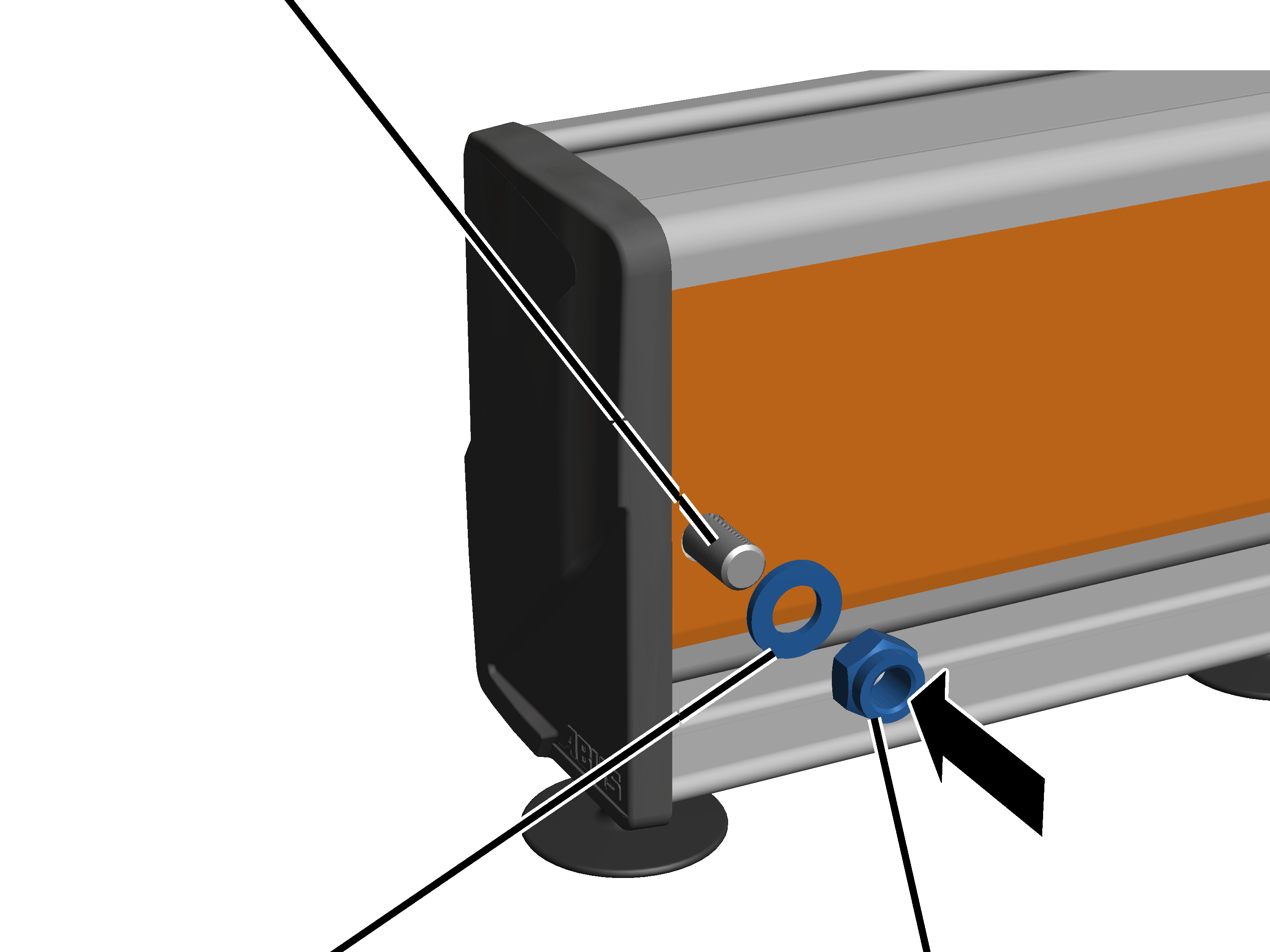
|
|
Washer |
Self-locking M12 nut |
Insert a hexagon head screw through the HB profile rail and the
spacer sleeve.
|
Size |
Hexagon head screw |
|
HB110 |
M12x85 |
|
HB150 |
M12x110 |
|
HB190 |
M12x110 |
|
HB240 |
M12x110 |
Insert washer, screw on the self-locking M12 nut. 80 Nm.
Fasten the flat cable as before on the fixed cable slider.
Fitting the end
caps
On all other HB profile rails:
Push the spacer sleeve into the end cap.
Only with HB240: use the spacer sleeve with black coating. It is
slightly longer than the spacer sleeve with silver or yellow coating.
Put on the end cap.
If necessary, widen the HB profile rail slightly to enable
insertion of the spacer sleeve.
|
Hexagon
head screw |
|
|
|
|
Washer |
Self-locking M12 nut |
Insert a hexagon head screw through the HB profile rail and the
spacer sleeve.
|
Size |
Hexagon head screw |
|
HB110 |
M12x85 |
|
HB150 |
M12x110 |
|
HB190 |
M12x110 |
|
HB240 |
M12x110 |
Insert washer, screw on the self-locking M12 nut. 80 Nm.