
At a glance:
General information
This section applies to anyone who lifts loads using the crane, performs work on the crane, or works nearby.
Read before starting work
Using this product manual
The following symbols are used in this product manual:
- This is an instruction regarding an action and prompts you to perform a work step.
- This is the result of an action and describes what happens on the device.
- This is a list.
Only with...
A section that appears in a box framed by a dashed line is only applicable for certain types, versions or options. The condition to which the section applies is specified at the beginning in the heading "Only with...".
Instructions for the product manual
Read the product manual through carefully before starting work. Also be sure to observe additional product manuals for accessories and components.
Afterwards, keep the product manual available in the vicinity of the crane. It must be accessible to all who work with or on the crane.
If the crane is sold on or hired out, always provide the product manual together with the crane.
Proper use
ABUControl is a modular crane control based on a central PLC and various CAN bus devices that communicate with each other via a CAN bus network. It is used for the control of an ABUS overhead travelling crane with one or several trolleys by using ABURemote radio remote control or an ABUCommander pendant control.
- ABUControl is a modular and interconnected crane control. All components of ABUControl are connected and aligned to each other. Individual CAN bus devices or other components may only be replaced by identical original spare parts.
- The ABUControl is only to be used with the ABUS-specific factory settings.
- Only use ABUControl on ABUS overhead travelling cranes. Do not connect any products from other manufacturers.
- Settings in KranOS may only be made by qualified personnel.
Regulations
The installation has been built and tested according to European standards, rules and regulations applicable at the time of its manufacture. The conventions applied during design and construction are specified in the Declaration of Conformity or the Declaration of Incorporation. The conventions must also be observed for installation, operation, inspection and maintenance, as must the applicable occupational health and safety regulations.
Which provision applies in individual cases will greatly depend on the crane's use and the national regulations. Review and observe all applicable and current regulations, including the occupational health and safety regulations. Refer also to the Declaration of Conformity or Declaration of Incorporation.
Warranty
- ABUS assumes no liability for damages that were caused by improper use, inadequately trained personnel, incorrect performance of work, nor for any changes, reconstruction or other modification of the crane or crane components which were not approved by ABUS.
- Any warranty claim becomes invalid if components were modified without consent, the crane or crane components were installed, used or serviced in any way other than that described in this product manual, or if parts other than original ABUS replacement parts were used.
- Safe operation of the crane or crane components is only guaranteed if original ABUS replacement parts are used.
Instructions regarding safety
Observe these instructions for safe handling of the crane. Special hazard notices are located in the corresponding sections in which the danger arises.
- Even after the emergency stop button has been pressed, life-threatening high voltages are still present in the crane control and in the trolley control.
- Before working on the crane, disconnect the power line and wait at least 15 minutes until the voltage has dissipated.
ABUControl
Description of the device
ABUControl consists of:
- Crane control
- Trolley control
- Absolute rotary encoder on the cable drum
- Load measuring system on the hoist
- Absolute rotary encoder on the hoist motor (optional)
- Distance sensor on the trolley or trolleys (optional)
- Distance sensor on the crane (optional)
- Additional motion restrictor (cross-type limit switch and/or reflective light barriers) (optional)
- LED matrix display
- Additional cross-type limit switches for building profile control (optional)
- Inclinometer on the trolley (optional
Overall view of the crane control:
The crane control set up varies according to the crane. The following figure can be used as a guide.
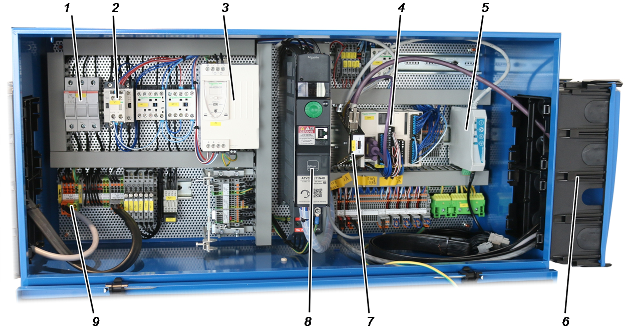
- 1: Fuse isolating link
- 2: Main contactor
- 3: Power pack
- 4: Field bus coupler for input and output signals
- 5: ABURemote receiver
- 6: Cable entry housing
- 7: CAN distributor
- 8: Frequency converter
- 9: Feed unit
Overall view of trolley control:
The trolley control set up varies according to the crane. The following figure can be used as a guide.
1 2 3 4 5
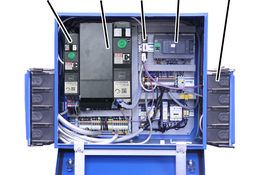
- 1: Trolley drive frequency converter
- 2: Hoist frequency converter
- 3: CAN distributor
- 4: PLC
- 5: Cable entry housing
Only with absolute rotary encoder "AWG"
Absolute rotary encoder "AWG" (on gear limit switch "GGS"):
- 1: Relay and pin multipoint connector for additional switching tasks (option)
- 2: Rotary switch for device address (option)
- 3: Button for resetting the device address
- 4: Circuit board
- 5: Switch for terminating resistor
- 6: Connection for CAN bus network and Modbus network
Only with "Kübler" absolute rotary encoder
"Kübler" absolute rotary encoder (on gear limit switch "GPK"):
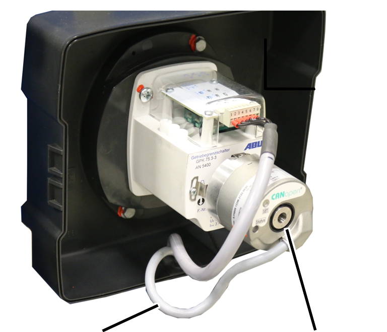
- 1: CAN bus line
- 2: "Kübler" absolute rotary encoder
Performance features
ABUControl:
- ABUControl is a modular crane control based on proven electronic components from automation technology. The various modules on the crane are networked together and thus an intelligent control of crane functions is the result.
- ABUControl works with a PLC as the central computing unit. It evaluates the control commands from the radio remote control or pendant control as well as all responses from the absolute rotary encoders, motion restrictors (cross-type limit switches, light barriers, etc.) and other modules. Based on this, ABUControl controls the crane drives and hoist drives.
- The drive axles (crane travel and trolley travel) are equipped with frequency converters. These enable ABUControl to conveniently set the movement profiles. On request, the hoist can also be equipped with frequency converters in order to select and set the hoist profiles for the hoist.
- The hook position of the hoist and the lifting speed are recorded by an absolute rotary encoder. Through this, ABUControl knows how fast the hoist is turning. This enables some convenient additional functions (e.g. hoist synchronisation control). The highest and lowest hook positions are additionally recorded via an electromechanical gear limit switch.
- A crane with ABUControl is controlled by an ABURemote radio remote control. With this, some additional functions (e.g. sway control) can be conveniently operated from the transmitter. If the crane is controlled by a different radio remote control, certain functions (e.g. sway control) are unavailable or only available to a limited extent.
- Only with pendant control (option): The crane can also be controlled by a pendant control. Some functions of ABUControl (e.g. sway control) cannot be used with a pendant control or can only be used to a limited extent.
- Various ABUControl operating information is displayed on the LED matrix display. It also shows status and error messages from various crane components, which enables quick and simple troubleshooting.
- Only with double lifting speed (option): With this option, the lifting speed can be increased up to 200% (= doubled). This means that the crane can be worked faster. The maximum possible additional lifting speed (from 100%) is dependent on the load attached.
- Only with super-precision lifting (optional): This function is used for especially slow lifting and lowering with the hoist. This enables extremely exact positioning of the load. Super-precision lifting can be switched on and off at the transmitter or the pendant control.
With activated super-precision lifting in pole-switchable hoist drives, the frequency converter is switched from winding with fast lifting speed to winding with slow lifting speed.
For single-winding hoist drives that are not pole-switchable, (e.g. GM7000.2), the speed of the hoist motor is monitored by the frequency converter using a separate absolute rotary encoder, thus also enabling full torque at very slow lifting speeds so that the load can be held until a standstill is reached even without braking.
KranOS:
- KranOS is a graphic user interface where ABUControl is set.
- Crane operators and (trained) repair staff can access KranOS on a computer (e.g. laptop, tablet) and change settings and display operating data there.
- To access KranOS, no special software or app is necessary. The access occurs through a normal Internet browser.
- Access to KranOS (except the display of operating data) is protected by usernames with passwords. The various users have different user levels. The higher the user level, the more settings can be opened and changed.
The wiring and programming of ABUControl:
- ABUControl consists of a central memory-programmable control (PLC) and numerous CAN bus devices (e.g. absolute rotary encoder, frequency converter, etc.) that communicate with each other via a CAN bus network.
- ABUControl is constructed from modular standard industry components that can be simply and individually replaced when required. This means that if there is a fault, replacement of the entire control is not necessary. Selective individual components can be replaced.
- All ABUControl modules can be connected with one another by plug-in connections. Thus the modules can be quickly separated from each other.
- Every crane with ABUControl has a customer-specific configuration. The control thus knows the exact design of the respective crane and the optional version components.
- The CAN bus devices are programmed after replacement by the central PLC. This occurs either automatically or through the corresponding function in KranOS, depending on the device.
- After a replacement, the central PLC must be provided with the customer-specific programming via an SD card. In this way, the customer-specific data of the crane is retained.
- ABUControl is designed from the ground up with EMC compliance. Thus disruptions to other devices and industrial systems by electromagnetic waves are effectively prevented.
- Control signals at the outputs and inputs of the central PLC, the frequency converters and the field bus couplers can be tested with conventional measuring devices.
- In addition to the CAN bus network, several components are connected with each other via an Ethernet network. This includes a WLAN module, so that a WLAN network connection can be established from a laptop or tablet computer to the PLC. If further Ethernet network devices are used (e.g. radio data transmission module), all of these Ethernet devices are connected to an Ethernet switch as distributor.
- In addition to the CAN bus network, several components may be connected with each other via a Modbus network.
The trolley travel synchronisation control:
- When there is more than one trolley on the crane, ABUControl regulates the synchronous travel of all trolleys in joint operation. The trolleys therefore have the same travel speed and also the same acceleration time and braking time in joint operation within tight tolerances.
- The transport of a joint load is made even safer with the trolley travel synchronisation control.
- The trolley travel synchronisation control also functions if the trolleys have different sizes and (each considered separately) different maximum travel speeds.
- The trolley travel synchronisation control is possible for up to three trolleys per crane.
For tandem operation: The trolley travel synchronisation control is possible for up to two trolleys per crane on both cranes in tandem operation.
The hoist synchronisation control:
- When there is more than one hoist on the crane and frequency converters, ABUControl regulates the synchronous lifting and lowering in joint operation. The hoists therefore have the same lifting speed and also the same acceleration time and braking time in joint operation within tight tolerances.
- The transport of a joint load is made even safer with the hoist synchronisation control.
- The hoist synchronisation control also functions if the hoists have different sizes and (each considered separately) different maximum lifting speeds.
- The synchronisation control also balances different hoist loads from uneven load distribution. Thus an unevenly distributed load can also be synchronously lifted and lowered by all hoists.
- The hoist synchronisation control is possible for up to three hoists per crane.
For tandem operation: The hoist synchronisation control is possible for up to two hoists per crane on both cranes in tandem operation.
- For twin hoists: The synchronisation control is deactivated in the area of the brake phase before the highest hook position. This ensures that the wire rope is distributed evenly on both cable drums.
The movement profiles:
- For drives with frequency converters: ABUControl allows adjustment of the drive control. Thus, hoist drive and drive can be adjusted to individual usage in the acceleration and braking behaviour as well as in the maximum and minimum speed.
- The setting parameters are limited so that the crane can only be set within safe limits. Otherwise an acceleration that was too strong could e.g. strain the supporting structure (building) too much.
- You can switch between a step-less and a two-step movement profile in the KranOS movement profile control.
- Thus, various cranes within your movement profile can be adjusted to each other to achieve a similar behaviour.
The overload protection:
- ABUControl records the attached load on all hoists and adopts the overload protection of all individual hoists and the crane total load. Furthermore, it monitors the rotational direction and rotational speed of all hoists and safely switches off if there is an overspeed.
- ABUControl directly measures the attached load.
- A load measuring system is used for recording the load. It consists of a load sensor or a measurement bolt.
- The load measuring system serves primarily in detecting an overload on the crane and not in precisely weighing a suspended load. Also for load display in the transmitter or in the LED matrix display it is only used for displaying a rough estimate of the load. The load measuring system cannot be calibrated. The load measuring system has an accuracy of ±2 to 5% of the maximum load capacity of the crane.
Building profile using cross-type limit switch (variant):
- The building profile comprises all characteristics of a building that could influence the crane travel, trolley travel and lifting/lowering of the crane. This includes the beginning and end of the crane track, obstacles, blocked-off areas, crane flaps and the like.
- The ABUControl building profile control enables the adaptation and restriction of all crane axes depending on the building profile. For example, the speed can be reduced in front of obstacles or an intermediate stop can be inserted at specific positions. Furthermore, areas can be completely blocked for passing through or partial load ranges can also be set up in a building.
- If the crane is equipped with a building profile control, the switching points for the braking function or shut-down of the crane and trolley are also integrated in the building profile control.
- The cross-type limit switches are used for recording the position of crane and trolley.
- An absolute rotary encoder is used for recording the position of the hoist.
- A load measuring system is used for recording the load. It consists of a load sensor or a measurement bolt.
The building profile control via the crane position (variant):
- The building profile comprises all characteristics of a building that could influence the crane travel, trolley travel and lifting/lowering of the crane. This includes the beginning and end of the crane track, obstacles, blocked-off areas, crane flaps and the like.
- The ABUControl building profile control enables the adaptation and restriction of all crane axes depending on the building profile. For example, the speed can be reduced in front of obstacles or an intermediate stop can be inserted at specific positions. Furthermore, areas can be completely blocked for passing through or partial load ranges can also be set up in a building.
- If the crane is equipped with a building profile control, the switching points for the braking function or shut-down of the crane and trolley are also integrated in the building profile control.
- A absolute value measuring system is used for recording the position of crane and trolley. This can be implemented via laser distance sensors or a magnetic tape in the conductor system, for example.
- An absolute rotary encoder is used for recording the position of the hoist.
- A load measuring system is used for recording the load. It consists of a load sensor or a measurement bolt.
- The obstacles can be created, teached-in, edited or deleted in KranOS.
- An obstacle is defined and created as a cuboid with two corner points.
If an obstacle is more complex, it can be made up of several cuboids, each of which is positioned over the two corner points. It is important to note that the cuboids will overlap, as the measuring systems have a certain margin of error.
The sway control:
- The sway control significantly reduces the swinging movement of the load hook during trolley and crane travel.
- The sway control is based on mathematical calculations. The travel speeds of the crane and trolley, the hook position and the distance from the load hook to the load's centre of gravity (and thus also the length of the lifting tackle) are taken into consideration. The travel motors are then accelerated and braked by ABUControl in such a way that the travel movement counters the swinging movement and thus diminishes it.
- The sway control can be switched on and off via ABURemote. The value set for the distance from the load hook to the load's centre of gravity can be changed via ABURemote.
- The sway control can only reduce the swaying by acceleration and braking through mathematical calculations. Other influences such as wind, hitting an obstacle or similar, cannot be offset.
- The acceleration and braking distances of cranes and trolleys do not alter considerably through the sway control.
- The sway control initially functions only with a single hoist or on a crane with several trolleys in individual control, providing the unused trolley is in the parking position (load hook triggers top hoist limiter).
During the joint operation of several trolleys or in tandem operation, the sway control must be separately enabled.
The calculation of the sway control only functions correctly in joint operation of multiple trolleys or in tandem operation if the distances to the load's centre of gravity are the same on both hoists. For a uniform collective load, the hook position and the length of the lifting tackle added together must result in the same total length in each case. Otherwise, the sway control could actually increase the swaying of the load.
The hook assistants (hook guidance and hook centring):
- The hook guidance allows the load hook to be moved by hand.
Both the crane and the trolley travel in the direction the load hook is moved or pulled. - The Hook centring function automatically positions the load hook vertically above the load "in lift" when the load is attached. This facilitates and speeds up positioning of the trolley vertically. This can reduce any diagonal pull.
- The hook guidance/hook centring function can be switched on and off using a quick-access button on the ABURemote radio control unit.
- The hook assistants work by precisely measuring the wire rope deflection. An inclinometer which measures the wire rope deflection is attached to the fixed point crosshead, the drum housing or the trolley frame. The inclinometer position can be adjusted in KranOS.
- To be able to use the function, perform a calibration run before startup
multiple times from the lower to upper switch-off point.
This determines the zero position of the inclinometer. The inclinometer calibration is activated in KranOS. - The hook assistants only work with a single hoist or on a crane with several trolleys in individual control, provided the unused trolley is not selected and in the parking position (load hook triggers top hoist limiter).
- If the hook guidance/hook centring is active, position control cannot be activated, i.e. that the functions cannot be used at the same time.
Positioning control:
- Using the positioning control, you can move to pre-determined positions (manual or linear) or a follow route with up to 8 positions. Positions (manual or linear) can be created or modified in KranOS.
Positions of a route points cannot be created or changed in KranOS.
- The positioning control is switched on and off using ABURemote. Target positions can be selected and saved on the ABURemote transmitter. See "ABUS radio remote control ABURemote" product manual.
- The sway control status cannot be changed when PTP positioning control and teach-in PTP are activated. Access to the sway control function is locked in these modes (direct access buttons and menu).
- Switching between individual/together when PTP or teach-in PTP is activated causes an error and the procedure cannot be completed correctly.
- The super-fine lifting activity cannot be changed whilst PTP positioning mode and PTP teach-in are active
The anti-collision device:
- The anti-collision device on the crane and trolleys prevents two cranes (two trolleys) being able to hit each other at high speed or at low speed.
- The anti-collision device functions via a reflective light barrier or a distance sensor with laser beam depending on the application.
- The reflective light barriers and the distance sensors can react in a sensitive manner to the influences of dust, snow or particulates in the air. If the light beam is disrupted, the crane or trolley brakes and stops.
The tandem control:
- Two overhead travelling cranes with a joint load can be controlled simultaneously with just one transmitter by the tandem control.
- The tandem control works in combination with the synchronisation control. ABUControl controls the synchronous trolley travel and crane travel in tandem operation as well as the synchronous lifting (optional). Thus, the cranes have the same speed in the crane axes with narrow tolerances as well as the same acceleration time and braking time.
- The tandem control makes the transport of a joint load even safer.
- The tandem control also functions if the cranes have different maximum load capacities and (each considered separately) different maximum speeds.
- Loads that exceed the maximum load capacity of an individual crane in the crane installation can be lifted with the tandem control. As the load affects both cranes, the maximum load capacity of both cranes can be added together, both for cranes with identical maximum load capability and for those with different maximum load capacities. For unbalanced load distribution the total maximum load capacity is correspondingly lower.
- In tandem operation, the ABUControl controls of both cranes are wirelessly connected together and mutually transmit the normal operating modes via a radio data transmission module.
- In doing this, the corresponding parameters (e.g. "Acceleration time", "Braking time" and "Speed Maximum") are compared between the two cranes and, as far as possible, adapted so that the cranes are compatible. The travel profiles must be set identically for both cranes (e.g. "Step-less").
- Thus, for example, all travel limit switches on the crane and trolley, hoist limit switches and the overload protection are jointly evaluated. If the crane stops in one of the crane axes, the other crane also always stops in the same crane axis. The other crane axes can be moved farther without an intermediate stop.
The electronic track guidance system (option):
- The electronic track guidance system can reduce unbalanced loads as well as wear on the wheel flanges of the wheels. These occur when, for example, the trolley with load is in the load hook on the left or right end of the main girder and the crane travels.
- In addition, the distance of both wheels of an end carriage from the crane track is measured. If the crane runs unevenly (e.g. due to an unbalanced load), ABUControl evens this out again automatically, via a differential control of the drives of both end carriages.
- This means that the wear on the wheel flanges and the crane track can be significantly reduced.
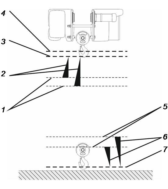
Gear limit switch:
Bottom hoist limiter
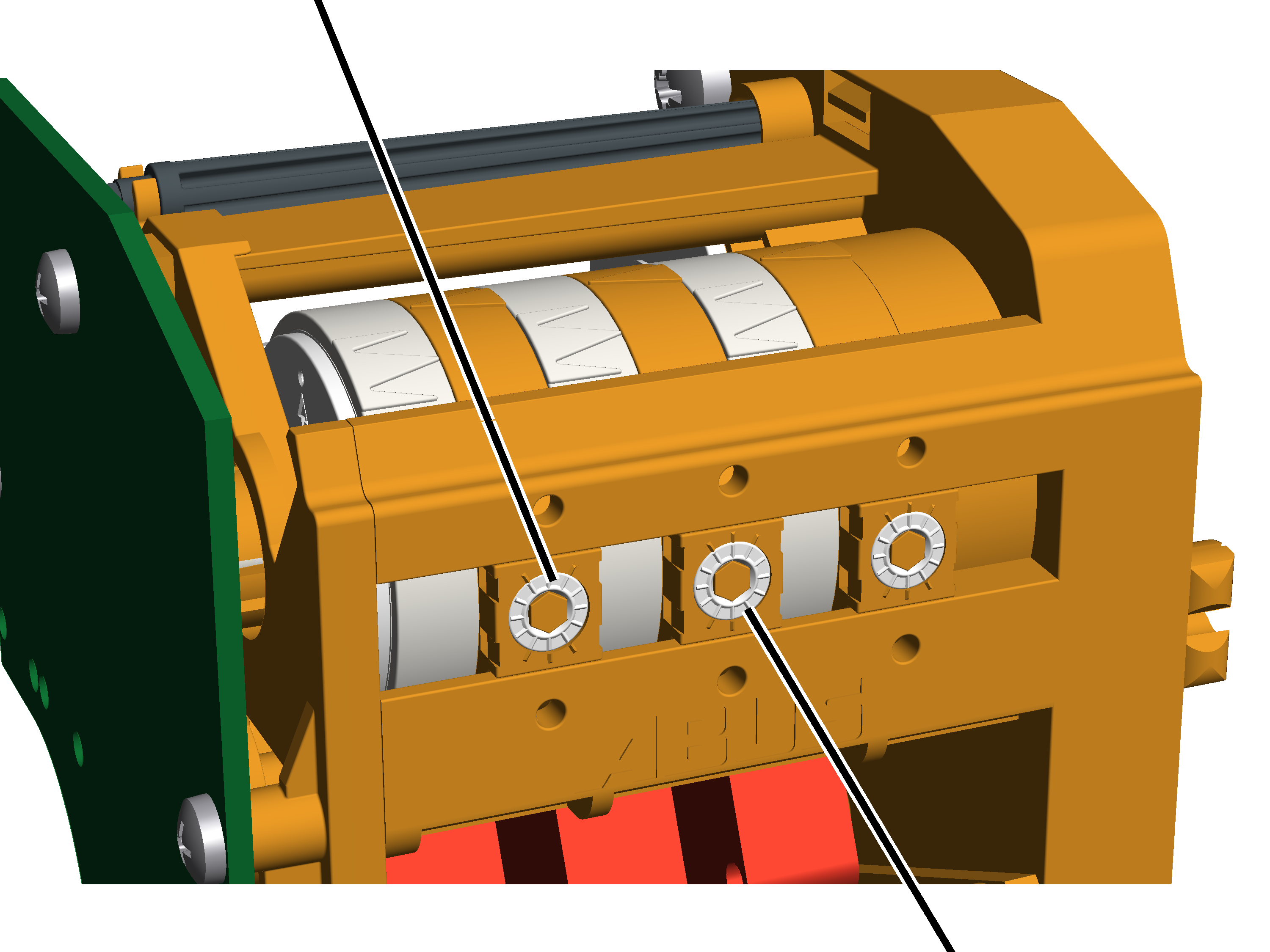
- The wire rope hoist has a gear limit switch that functions as a mechanical hoist limit switch. It is directly coupled with the cable drum. It ensures that the load hook does not travel farther than the highest hook position or the lowest hook position.
- The upper switching point is called the "top hoist limiter" (middle adjusting screw); the lower switching point is called the "bottom hoist limiter" (left adjusting screw).
- Shortly before the load hook reaches the switching point of a hoist limiter, ABUControl slowly brakes the hoist motor. This method means that the switching points of the hoist limiter are only activated with a slow lifting speed.
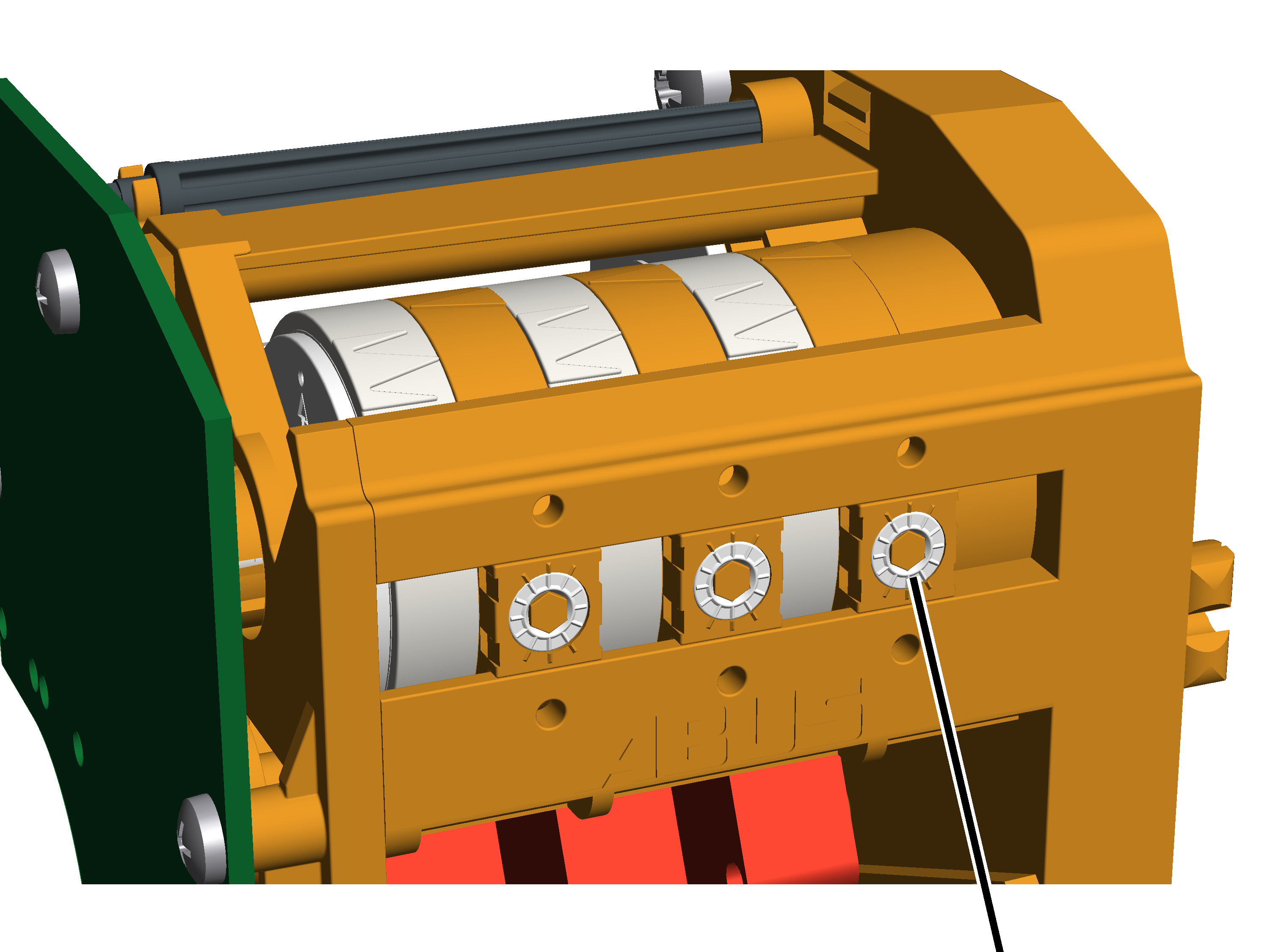
- To additionally increase safety, the gear limit switch has another switching point. It is called the "Backup limiter" (right adjusting screw). It is located above the top hoist limiter and serves as an additional switching point when lifting.
- If the top hoist limiter should fail and the load hook then travels over the switching point of the top hoist limiter, ABUControl switches the entire crane off. The backup limiter has been set at the factory and is tamper-proof. The backup limiter has been set in the factory and sealed.
The gear limit switch without normal operative travel to the top hoist limiter:
- The top hoist limiter must not be travelled to during normal operation. If it is travelled to, the load hook stops at the switching point of the top hoist limiter. The backup limiter switching point is above the top hoist limiter switching point and can therefore not be activated in a normal case.
- If the hoist limit switch is incorrectly set or has a technical fault, the backup limiter may nevertheless be activated. The backup limiter must then be bridged so that the crane can be switched on again. In this case, contact your ABUS Service representative. See “ABUS Service”.
The gear limit switch with normal operative travel to the top hoist limiter:
- If the highest hook position must be travelled to in normal operation, the top hoist limiter is frequently activated and can fail because of this. In this case, the backup limiter ensures that the crane comes to a safe stop. So that the backup limiter can be regularly tested, the wire rope hoist has a toggle switch with which the top hoist limiter can be manually bridged and the crane can be manually switched on again after the test.
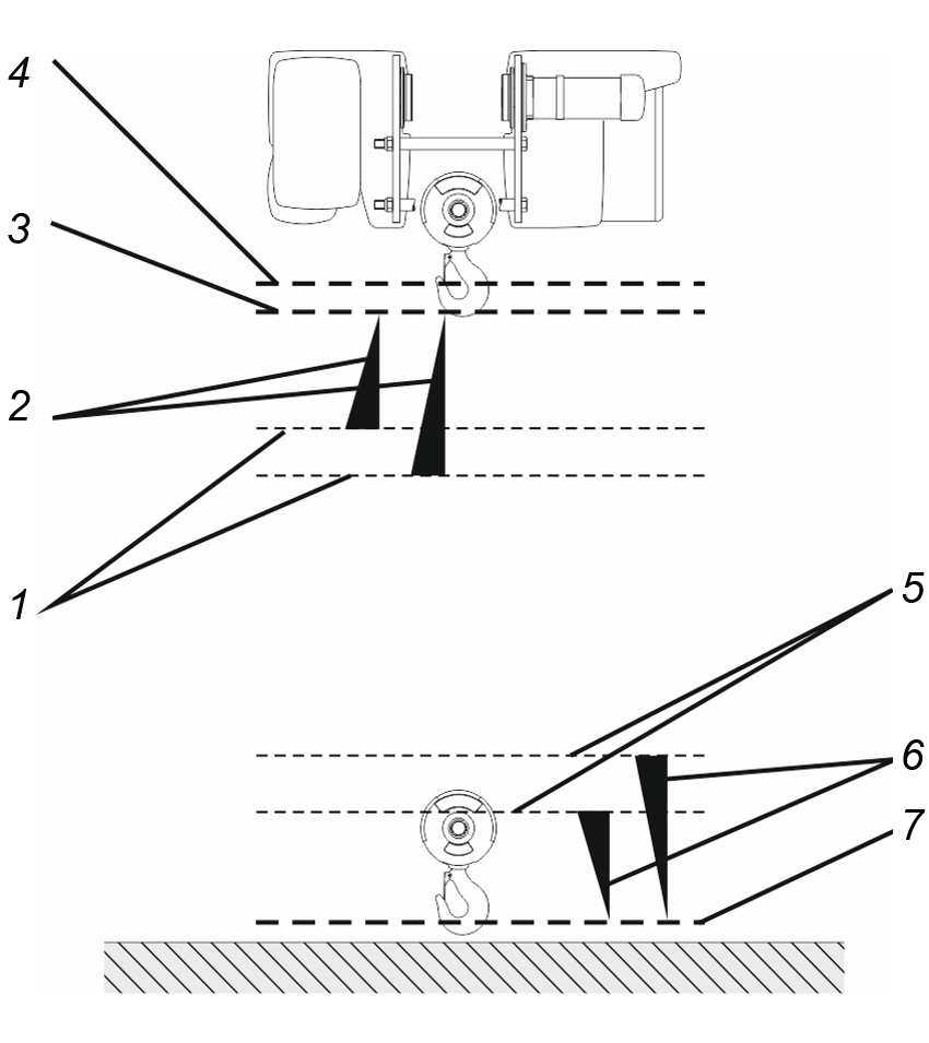
- 1: ABUControl begins the hoist drive brake phase shortly before the highest hook position. ABUControl individually calculates at which point the brake phase begins each time, depending on the current lifting speed. If the load hook travels upwards quickly, the brake phase begins earlier. If the load hook travels upwards slowly, the brake phase begins later.
In certain cases (e.g. with crossheads), a special hoist limit switch can be used. The start of the brake phase is then not individually calculated, but lies at a defined switching point.
- 2: Brake phase. How strong or gentle the brake phase is can be set in KranOS.
- 3: Switching point of the top hoist limiter. If it is activated, the load hooks stands still. Due to the individual beginning of the brake phase and the adjustable strength of the brake phase, the load hook only lifts with slow lifting speed shortly before reaching the top hoist limiter.
- 4: Switching point of the backup limiter. If it is activated, ABUControl switches the entire crane off.
- 5: Start of the brake phase, individually calculated each time, depending on the current lifting speed.
- 6: Brake phase.
- 7: Switching point of the bottom hoist limiter.
Discard prognosis
- The discard prognosis of ABUControl is used in calculating the maximum acceptable wear of the wire rope. It determines the wear of the wire rope and supports the examiner in the regular inspection by displaying the wire rope sections with the greatest wear.
- The main cause of wire rope wear on the wire rope hoist are the cyclic bendings. This is the number of bends that a particular wire rope section makes over the course of time over the individual reels on the bottom block and the deflection roller crosshead as well as on the cable drum.
Not only the number of cyclic bendings of a wire rope section but also the weight of the currently suspended load considerably influences whether or not broken wires will occur in the bent wire rope section during a cyclic bending.
- During running operation, ABUControl calculates the position at which the wire rope section is currently located. For wire rope sections running directly onto or off a reel, the suspended load is factored in and the corresponding wear for this rope section is saved (and used along with the other already saved values).
- The calculation of the maximum acceptable wear of the wire rope is no substitute for the regular inspection of the wire rope or for the inspection by the crane operator at the start of work. The intervals between the regular inspections are likewise not extended. Exterior damage (e.g. mechanical damage due to the wire rope sliding against an object) is also not taken into account.
Technical data
Electrical connection: |
|||
|---|---|---|---|
Nominal voltage |
380 V |
400 V |
415 V |
Operating voltage |
370 – 400 V |
375 – 420 V |
380 – 435 V |
Mains frequency |
50 Hz |
50 Hz |
50 Hz |
Control voltage |
24 V DC |
24 V DC |
24 V DC |
Electrical connection: |
|||
|---|---|---|---|
Nominal voltage |
440 V |
460 V |
480 V |
Operating voltage |
425 – 460 V |
430 – 485 V |
445 – 505 V |
Mains frequency |
60 Hz |
60 Hz |
60 Hz |
Control voltage |
24 V DC |
24 V DC |
24 V DC |
Ambient conditions for operation: |
|
|---|---|
Ambient temperature |
-5 °C to 40 °C |
Ambient temperature |
+40 °C to +65 °C |
Installation altitude |
Up to 1000 m above sea level |
ABUControl can also be used at a reduced duty cycle and switching rate and also at an ambient temperature from +40 °C to +65 °C.
Operation at higher ambient temperatures:
Duty cycle of drives according to type plate |
Modified duty cycle at ambient temperatures of |
|---|---|
60 % |
30 % |
50 % |
25 % |
40 % |
20 % |
- For ambient temperatures of +40 °C to +65 °C, reduce the duty cycle according to the tables.
Operation at higher elevations:
At higher elevations, the crane will be less well cooled due to the reduced air pressure.
- Reduce the duty cycle at higher elevations.
System requirements for computer
To be able to work with KranOS, a computer (e.g. laptop, tablet) is necessary. The device must fulfil the following system requirements:
- WLAN adapter (for establishing a wireless data connection with ABUControl)
- Standard Internet browser (for opening KranOS) with HTML5 support and JavaScript. The browser Google Chrome should preferably be used.
- The TCP/IP Internet protocol must be available at the WLAN adapter. The IP address should be obtained automatically (DHCP should be active). Both are usually the case.
Disposing of ABUControl components
If components of ABUControl are to be disposed of:
- The entire control should be dismantled as much as is possible.
- Observe local regulations concerning disposal and recycling.
- Dispose of the individual parts sorted by material in an environmentally sound manner.
- Dispose of electronic components as scrap electronic parts.
- Dispose of cables and plug-in connections as scrap electronic parts.
- Dispose of steel sheet housing as waste metal.
- Plastic housing and plastic parts should be recycled as plastic waste.

Logging into and registering in KranOS
To change settings on ABUControl, a WLAN connection to ABUControl must be established with a WLAN-capable computer (laptop, tablet) for logging into KranOS.
Access to KranOS (except the display of operating data) is protected by usernames with passwords. The various users have different user levels. The higher the user level, the more settings can be opened and changed.
There are two user levels in ABU Control for KranOS access.
- User level [1] is "CUSTOMER" and includes read access. This allows access to diagnostic and display functions. This user level is therefore particularly relevant for the crane operator.
- User level [2] is "SERVICE" and includes authorisation to adjust the crane's settings. This makes this user level important for service work or maintenance.
The end user is responsible for the decision as to which persons or group of persons can be given knowledge of the usernames ("CUSTOMER" or "SERVICE") and the associated passwords.
Establishing WLAN connection
The figures show a WLAN connection to a PC with Windows 10. A WLAN connection is established differently for other operating systems on tablets, computers and smartphones.
- Bring the laptop as close as possible to the crane, e.g. set it up directly beneath the crane.
- Note the crane serial number of the crane that the connection should be established with.
The crane serial number is located, for example, on a sticker on the main girder.
- If necessary: activate the WLAN adapter on the laptop.
Crane WLAN networkInput field for network key
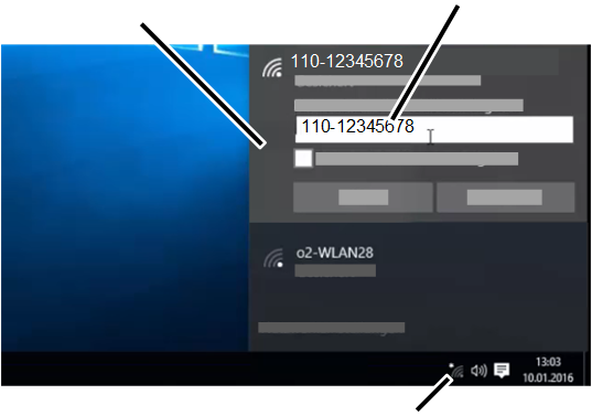
- Click on the symbol for the available WLAN networks in the system bar at the bottom right.
- Select the WLAN network with the name (SSID) which corresponds to the crane serial number in the list of available WLAN networks and connect.
- Every crane has its own WLAN network.
- The network name (SSID) is identical with the crane serial number and is unique.
- Enter the same character sequence for the network key again (with or without hyphens and/or blank spaces, exactly as it is on the network name (SSID)).
- The laptop will connect with the ABUControl WLAN.
Logging into KranOS
Address line with IP address for accessing KranOS
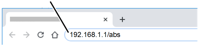
- Open the browser on the computer.
- Enter the address "192.168.1.1/abs" in the address line of the browser.
Enter "192.168.1.2/abs" for the second of two cranes in tandem operation.
- Press the Enter button.
"Login" button
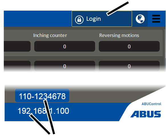
- The "Operating data" window appears.
The most important operating data of the crane can be read here. See "Reading operating data and load population recorder".
- The IP address and the crane serial number of the crane are displayed.
The IP address shown here is the IP address of the PLC. This is a different IP address than that for accessing KranOS in the browser.
- Check the displayed IP address and crane serial number, and make certain that the connection with the right crane was established.
In case of doubt, switch to one of the crane axes in KranOS and check whether the corresponding motion is displayed in KranOS when the button is held depressed. See "Display status of crane axes".
- Click the "Login" button.
Logging into KranOS
"Password" input field"User" input field

- The KranOS "Login" window appears.
- Use capital letters and enter the username:
- Username for user level [1]: "CUSTOMER"
- Username for user level [2]: "SERVICE"
- Enter password:
- Password for user level [1]: "CUSTOMER" (default password)
The default password for the "CUSTOMER" user can be changed after registration if required.
- Password for user level [2]: "SERVICE" (default password for first login)
The default password for the "SERVICE" user can be changed as required. It must also be changed after initial registration. See "Changing the password for KranOS".
- Click "Login".
- The start window appears.
Note:
If there is no work on the KranOS for 30 minutes, the user is automatically logged out.
No connection to the PLC:

- If the connection to the PLC is lost, for example due to a damaged or disconnected cable, it is not possible to log in to KranOS.
- A warning appears: "PLC not accessible. Please check the connection. The values displayed here may be incorrect."
Connection between KranOS and PLC
The connection of KranOS and PLC is displayed in the start window.
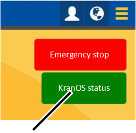
- The description field "KranOS status" shows the status of the connection of KranOS to the PLC:
- Description field has a green background: Connection is established.
- Description field has a red background: Connection is interrupted. KranOS can be used, but the displayed values are possibly incorrect.
Reestablishing the connection:
- Close the browser on the computer.
- Reopen the browser.
- Log in to KranOS again. See "Logging into KranOS".
Empty the browser cache on the computer:
The cache saves browser data from already visited websites. Normally this accelerates calling up websites. With KranOS however, this can lead to display problems. The cache should then be emptied.
- In the "Google Chrome" browser: Press Ctrl + Shift + Del.
- The cache is emptied and the connection is re-established at the next opening of KranOS.
Operating KranOS
For this work step, access from a laptop or tablet computer to KranOS is necessary. The user "SERVICE" (user level ‚[2]) or "CUSTOMER" (user level [1]) must be logged in.
- Log in to KranOS with user "CUSTOMER" (user level ‚[1]) or "SERVICE" (user level [2]). See "Logging into and registering in KranOS".
KranOS displays
After logging in:
"Back" button"User" menu
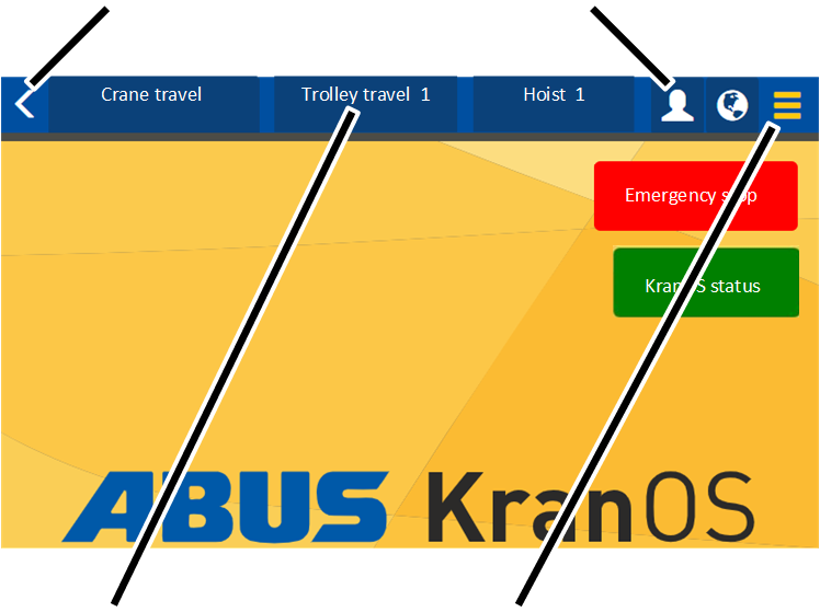
- Main menu:
The window associated with each crane axis (crane travel, trolley travel, hoist) can be selected here. Only crane axes that are actually available on the crane are displayed.
- "Settings" menu (three horizontal bars):
Three yellow bars: A menu with menu items that match the current window appears here.
Three black bars: No menu items are available for the current window.
- "Back" button (yellow arrow):
Here you can switch back to each previously displayed window.
- "User" menu (white figure):
A menu with menu items relevant to the logged in user appear here:
Change password: See "Changing the password for KranOS".
Logout: See "Logging out of KranOS".
In one of the windows:
Text field and input fieldButton (blue background)
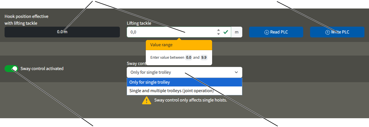
- Selection field (white background): Here you can select a specified value from a list. See "Selecting value".
- Input field (white background): Numerical values can be entered here. See "Entering value".
- Description field (dark background): Numerical values are displayed here. They cannot be changed.
- Button (blue background): Buttons can be clicked on. They lead to another window or perform an action.
Main menu (crane axes)
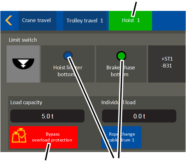
- Main menu (crane axes) (blue or green background):
- Control signals (blue or green):
Terminal or device has a green background: there is voltage present or the motion restrictor has not been triggered.
Terminal or device has a blue background: there is no voltage present or the motion restrictor has been triggered.
- Button (red background): Buttons with safety-relevant functions (e.g. Bypass overload protection) have a red background as soon as they are switched on (active).
Opening and closing menus and menu items
To open the menus and menu items:
"Crane travel" menu item for crane axis
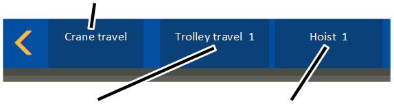
- Click on the menu item for the desired crane axis in the main menu.
Only menu items for crane axes that are actually available on the crane are displayed (e.g. trolley 2).
Selected menu item (crane axis)"Settings" menu
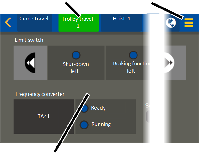
- The selected menu item (crane axis) has a green background.
- The corresponding contents are displayed in the display area.
- If there are further menu items for the selected menu item (crane axis): The "Settings" menu is yellow.
Switching to another menu:
Other menu items (crane axes)
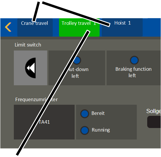
- Click on one of the other menu items (crane axes) in the main menu.
- The newly selected menu item (crane axis) has a green background.
- The corresponding contents are displayed in the display area.
Main menu as selection field
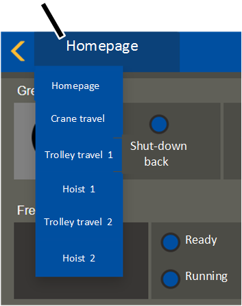
- On smaller displays (e.g. with a smaller tablet computer), the main menu for the crane axes is shown as a selection field.
- Click on the "Homepage" button.
If a different crane axis is called up instead of the homepage, this is shown on the button.
- The main menu is displayed with the crane axes.
- Click on the menu item for the desired crane axis.
Opening settings:
"Settings" menu
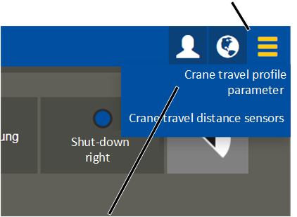
- Click on the "Settings" menu.
- A menu with menu items that match the current window appears here.
Switching back to the previous menu:
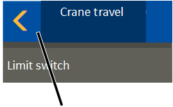
- Click on the "Back" button.
- KranOS switches to the previously displayed menu item.
Switching back to the start window:
- Depending on the window displayed: click on the "Back" button once or several times.
- The start window appears.
Entering value
Numerical values can be entered for some functions.
An input field with a white background is displayed in the window:
Input field with yellow border and green tickInput field with yellow border and red exclamation mark
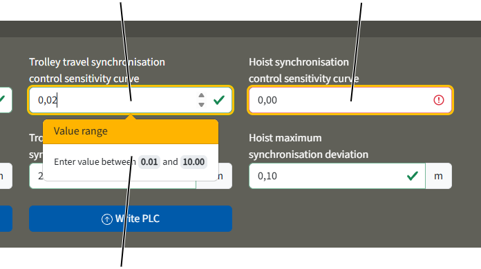
- Click input field.
- Arrow buttons appear for changing the values.
- The value range with the minimum and maximum permitted values is shown under the input field, if available.
- Enter the desired value with the keyboard, or increase/reduce the value using the arrow buttons.
- If the new value lies within the permitted value range, a green tick appears next to the input field.
- If the new value lies outside the permitted value range, a red cross appears next to the input field. The input field background also becomes red.
- If the value was changed, a yellow border appears around the input field.
The value is not yet saved in ABUControl. See "Saving values in ABUControl".
Selecting value
For some functions, values (e.g. various settings) can be selected from a selection field.
Selection field
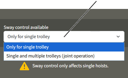
- A selection field with a small arrow pointing downwards is displayed in the display area.
- The currently selected value is displayed in the selection field.
- Click on selection field.
- The possible values are displayed under the selection field.
- Click on the desired value.
- The selected field is closed and the new value is adopted.
- If the value was changed, a yellow border appears around the input field.
The value is not yet saved in ABUControl. See "Saving values in ABUControl".
Saving values in ABUControl
After one or several values have been entered or selected within a window, the values must be transmitted to ABUControl.
Every time a window is opened, the currently set values are read from ABUControl and displayed. If values are input or selected but not saved, the next time the window is opened the original values that are still saved in ABUControl are displayed again.
After new values are input or selected:
Input field with yellow border
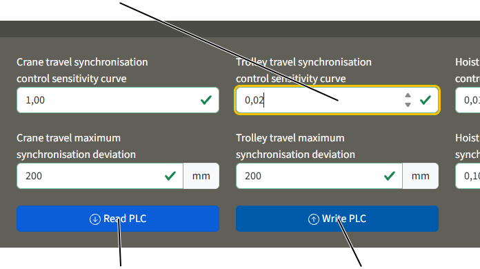
- If the value was changed, a yellow border appears around the input field or the selection field.
Changing additional values:
- Press the TAB button to jump to the next input field or selection field.
There you can change additional values as described previously.
- The new values are not yet saved.
Saving values individually or all together:
- Press the ENTER button.
or
Click on the "Write PLC" button.
- The message "Processing..." appears.
- A green tick appears in the centre of the screen.
- The new values are saved in ABUControl.
In some windows, several "Read PLC" and "Write PLC" buttons are available. The buttons are then applicable for the area that is summarised by colour (through different levels of grey).
If the values are not to be saved:
- Click on the "Read PLC" button.
- The original values that are still saved in ABUControl are displayed again.
If one or more values are invalid when saving:
- If the new value lies outside the permitted value range, a red cross appears next to the input field. The input field background also becomes red.
- An error message is displayed.
What the error message looks like depends on the browser used.
- So long as only one value is invalid when saving, none of the values on the current page are saved.
A red cross appears in the centre of the screen:
- An error occurred when saving the values.
- Reload the current page.
- Enter the desired values again.
- Click on the "Write PLC" button.
- If the problem persists, re-establish the connection of KranOS and PLC. See "Connection between KranOS and PLC".
Logging out of KranOS
If there is no work on the KranOS for 30 minutes, the user is automatically logged out.
For manual logging out:
"User" menu"Logout" menu item
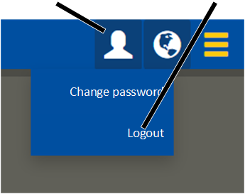
- Click on "User" menu.
- The menu appears.
- Click on the "Logout" menu item.
- The user is logged out.
- The "Operating data" window appears.
Changing the password for KranOS
The default password "SERVICE" for the user "SERVICE" (user level [2]) can be changed if necessary; it must also be changed after the first login. The default password "CUSTOMER" for the user "CUSTOMER" (user level [1]) can be changed if necessary.
The new password should be kept safe by the end user (e.g. in the service logbook in the crane or trolley panel) and should only be shared with the relevant group of people.
Overview: Navigation in KranOS |
|---|
User "CUSTOMER" or "SERVICE" 🡪 "User" 🡪 "Change password" |
- Log in to KranOS with user "CUSTOMER" (user level [1]) or "SERVICE" (user level [2]). See "Logging into and registering in KranOS".
- Click on "User" menu.
- The menu appears.
- Click on the "Change password" menu item.
"New password" input field"Old password" input field
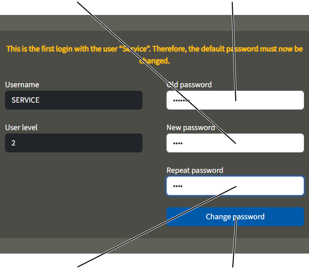
- The "Change password" window appears.
- Enter the previous password in the "Old password" input field.
- Enter the new password in the "New password" input field.
- Reenter the new password in the "Repeat password" input field.
- Click on the "Change password" button.
- The password has been changed.
Note:
Make a note of the new password in a suitable place (e.g. in the service logbook in the crane or trolley panel). The default "Service" password is no longer valid if the password has been changed. If you forget the new password, ABUS Service can reset the password. See "ABUS Service".
Note:
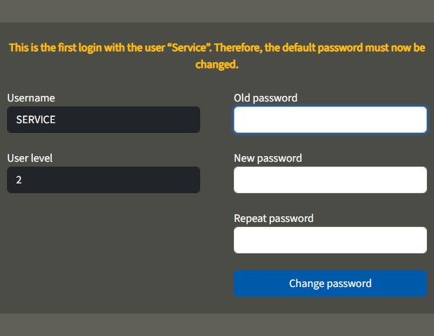
The first time you log in using the "SERVICE" account, the "Change Password" window will appear automatically, along with a message stating that the password must be changed.
You will not be able to access KranOS again until the password has been changed.
Setting the language
KranOS and the messages on the LED matrix display are shown in German by default. The language can be changed when you log in to KranOS.
For this work step, access from a laptop or tablet computer to KranOS is necessary. The user "CUSTOMER" (user level ‚[1]) or "SERVICE" (user level [2]) can be logged in. However, access is also possible without login (user level [0]).
Setting language
- Click on the "Language" button (globe).
- A list is displayed with the available languages.
- Select the desired language.
- KranOS and the messages on the LED matrix display are switched to the selected language.
Overview of menus
Menu item |
Menu item |
Menu item |
Functions |
User level |
See |
|
|---|---|---|---|---|---|---|
After logging in |
"Operating data" |
Reading operating data |
Without |
|||
Reading load population recorder |
Without |
|||||
Reading IP address of crane |
Without |
|||||
"Login" |
Log in to KranOs with a user |
Without |
||||
Start window |
"Operating data" |
Reading operating data |
Customer [1] Service [2] |
|||
Reading load population recorder |
Customer [1] Service [2] |
|||||
"PLC diagnosis" |
Displaying version information |
Customer [1] Service [2] |
||||
Displaying log file |
Customer [1] Service [2] |
|||||
Restarting crane |
Service [2] |
|||||
"Bus diagnosis" |
Displaying the bus network diagnosis |
Customer [1] Service [2] |
||||
"Additional PLC diagnosis" |
Show error and switching statuses of the additional PLC |
Customer [1] Service [2] |
||||
Setting operating mode number |
Service [2] |
|||||
"PLC sequences diagnosis" |
Displaying the PLC sequences process |
Customer [1] Service [2] |
||||
"Set PLC time" |
Setting PLC date and time |
Service [2] |
See "Setting date and time". |
|||
"PLC SD card" |
Data backup, restoration |
Service [2] |
||||
"Movement profile" |
Selecting movement profile |
Service [2] |
||||
Setting individual control |
Customer [1] Service [2] |
|||||
Menu item |
Menu item |
Menu item |
Functions |
User level |
See |
|---|---|---|---|---|---|
Setting synchronisation control |
Service [2] |
||||
Setting parameters for hook guidance and hook centring |
Service [2] |
||||
Inclinometer orientation |
Service [2] |
||||
Reset frequency converter to factory setting and measure hoist motor again |
Service [2] |
"Resetting frequency converter and measuring hoist motor again". |
|||
Reparametrizing frequency converter |
Service [2] |
||||
Bridging travel limit switch and hoist limiter |
Service [2] |
"Temporarily bridging travel limit switch and hoist limiter". |
|||
Switching crane travel direction and trolley travel direction |
Service [2] |
||||
Building profile control (via crane travel profile) |
Creating. teaching, copying, editing and deleting an obstacle |
Service [2] |
|||
Selecting and showing an obstacle |
Customer [1] Service [2] |
||||
"Load-controlled switching points" |
Setting load-controlled switching points |
Service [2] |
|||
Setting slack rope detection |
Service [2] |
||||
Positioning control |
Editing positions of the linear positioning control |
Service [2] |
|||
Specifying the tolerance defaults for positioning control |
Service [2] |
||||
Calculate the length of the crane track |
Service [2] |
Menu item |
Menu item |
Menu item |
Functions |
User level |
See |
|---|---|---|---|---|---|
"Crane travel" crane axis |
Displaying current positions of the limit switches |
Customer [1] Service [2] |
|||
Displaying frequency converter status |
Customer [1] Service [2] |
||||
Displaying building profile switch positions |
Customer [1] Service [2] |
||||
Displaying the status of the crane distancing system and the load-dependent crane distancing system |
Customer [1] Service [2] |
||||
"Crane travel profile parameter" |
Setting speeds |
Service [2] |
"Setting advanced travel profile parameters (crane travel profile, trolley travel profile)". |
||
Setting braking time and acceleration time |
Service [2] |
||||
Setting text speed of the load display |
Service [2]] |
||||
Setting part load |
Service [2] |
||||
Setting rotation direction of the cross-type limit switch for building profile |
Service [2] | ||||
"Crane travel distance sensors" |
Activating shut-down teach-in mode |
Service [2] |
|||
Activating braking function teach-in mode |
Service [2] |
||||
Set the length of the main girder and crane track |
Service [2] |
||||
"Trolley travel" crane axis |
Displaying current positions of the limit switches |
Customer [1] Service [2] |
|||
Displaying frequency converter status |
Customer [1] Service [2] |
||||
Displaying the status of the crane distancing system and the load-dependent crane distancing system |
Customer [1] Service [2] |
||||
Safety PLC crane travel |
Showing the error and switching statuses of the safety PLC |
Customer [1] Service [2] |
|||
Safe stop test mode (STO) |
Service [2] |
||||
Displaying building profile switch positions |
Customer [1] Service [2] |
Menu item |
Menu item |
Menu item |
Functions |
User level |
See |
|---|---|---|---|---|---|
"Trolley travel profile parameter" |
Setting speeds |
Service [2] |
"Setting advanced travel profile parameters (crane travel profile, trolley travel profile)". |
||
Setting braking time and acceleration time |
Service [2] |
||||
Setting text speed of the load display |
Service [2] |
||||
Setting rotation direction of the cross-type limit switch for building profile |
Service [2] |
||||
"Trolley travel distance sensors" |
Activating shut-down teach-in mode |
Service [2] |
|||
Activating braking function teach-in mode |
Service [2] |
||||
"Hoist" crane axis |
Displaying current positions of the limit switches |
Customer [1] Service [2] |
|||
Displaying frequency converter status |
Customer [1] Service [2] |
||||
Load display |
Customer [1] Service [2]] |
||||
Activating overload bridging |
Service [2] |
||||
Activating wire rope change |
Service [2]] |
||||
"Absolute rotary encoder" |
Setting device address |
Service [2] |
|||
Referencing absolute rotary encoder |
Service [2] |
||||
Reset error |
Service [2] |
||||
"Hoist profile parameter" |
Setting speeds |
Service [2] |
|||
Setting braking time and acceleration time |
Service [2] |
||||
Setting load measuring system |
Service [2] |
||||
Displaying wire length |
Service [2] |
||||
Setting measurement of hoist motor |
Service [2] |
Menu item |
Menu item |
Menu item |
Functions |
User level |
See |
|---|---|---|---|---|---|
Setting the max. travel speed for crane and trolley travel with hook guidance and hook centring |
Service [2] |
||||
Set the maximum travel for crane and trolley with the anti-tilt device |
Service [2] |
||||
"Sway control parameter" |
Setting lifting tackle |
Customer [1] Service [2] |
|||
Displaying wire length |
Service [2] |
||||
Switching sway control on and off |
Service [2] |
||||
Setting availability of sway control for multiple trolleys |
Service [2] |
||||
"Inclinometer parameters" |
Calibrating the inclinometer |
Service [2] |
|||
"Maximum acceptable wear parameter" |
Viewing parameters for the calculation of the maximum acceptable wear |
Customer [1] Service [2] |
"Displaying parameters for maximum acceptable wear and data of the rope drive". |
||
"Hoist calibration" |
Calibrating load measuring system |
Service [2] |
"Calibrating the load measuring system with an increased test load". |
||
Basic calibration of the load sensor |
Service [2] |
||||
Setting hoist limiter |
Service [2] |
"Temporarily changing the end position of the brake phase of the hoist drive" |
|||
Setting load population recorder |
Service [2] |
"Entering the start value for the load population recorder". |
|||
"Wear maximum acceptable wear" |
Displaying wear data of the individual wire rope sections |
Customer [1] Service [2] |
"Inspecting wire rope with the aid of the discard prognosis". |
||
"User" menu |
"Change password" |
Changing password |
Customer [1] Service [2] |
||
"Logout" |
Logging out user |
Customer [1] Service [2] |
|||
"Language" menu |
Setting language |
Without |
Installing and connecting
This section applies to anyone who works on the crane prior to its use
The end user of the crane is responsible for the proper qualifications of the commissioning personnel.
Examples of qualified persons:
- Persons with comprehensive knowledge from specialist training in engineering and in the electrical systems of cranes.
- Persons with sufficient experience in the operation, installation and maintenance of cranes.
- Persons with comprehensive knowledge regarding the relevant technical rules, directives and safety regulations applicable in the respective country.
- Persons receiving regular training from ABUS.
ABUS assumes no liability for damage due to incorrectly performed commissioning work done by unqualified personnel.
ABUS recommends having the commissioning work performed by the ABUS assembly team.
Installing the conductor system and absolute value measuring system
Only with positioning control
An absolute position measuring system is used for positioning control and building profile control based on the crane's position, in order to measure the crane's absolute position along the crane track. Either laser distance sensors or the APOS conductor system are used as the absolute position measuring system. With the APOS conductor system, a code strip is inserted into the profile of the conductor system; this is scanned by a reader head, which uses it to determine the position of the crane.
The installation of the APOS conductor system is described in a separate document. The following section sets out important additional information and ABUS-specific installation steps that differ from the installation instructions provided by the manufacturer of the APOS conductor system.
General notes:
- The code strip is manufactured in lengths of 260 m. Sections suitable for the specific crane system ordered are then cut from this. The starting count value of the code strip can therefore be significantly greater than 0.
- The code strip and the fixing profile are supplied with a surplus length of approx. 1 m.
- Once the code strip has been installed, it is no longer possible to replace individual track sections. Nor is it possible to open the conductor system along the track to replace a pantograph or the reader head carriage.
- The code strip is highly magnetic and should be protected from contamination (particularly from metal dust, shavings, etc.) both before and during installation.
Notes on installation:
- When feeding the code strip into the conductor system, the counting direction of the conductor system is important. The counting direction must be ascending in the "forward" direction of crane travel!
The position of the code strip is specified in the separate documentation and in the manufacturer's installation plan as being in the duct below the protective conductor (PE). However, this is not always the case. As the reader head can only be mounted on the reader head carriage in one direction, the code strip may instead need to be routed through the duct opposite the protective conductor.
- The code strip may be damaged when securing the fixed point of the conductor system. When tightening the self-tapping screws, ensure that they are screwed straight into the profiled rail.
- The reader head is inserted at the end of the system. If there are several cranes on the same crane track, care must be taken to ensure that the order of the pantographs is observed.
- The ends of the conductor systems consist of 150 mm long sections without a copper rail, fitted with a fixed end cap. The section is held in place solely by the end cap and not additionally by the copper rails. If necessary, an additional suspension should be fitted here.
- The drive rod with the M10 swivel head on the reader head carriage is secured to the crane's square tubes using a mounting bracket. A spacer sleeve ensures that the swivel head can move. The drive rod must therefore be aligned in line with the conductor system and the reader head.
- The track supply units are factory-fitted to the conductor system. To this end, the joint cover cap is cut out in the area of the code strip and fitted with new plastic parts. However, if the code strip has been fitted opposite the protective conductor, a special track supply unit must be used. Alternatively, the track supply can be modified on site. To do this, remove the end cap and unscrew the 4 screws on the lower section. Then rotate the lower section by 180 degrees and refit it. Note: This also rotates the supply point (screw connection).
- The reader head is equipped with an SSI (Synchronous Serial Interface). The 8-pin M12 connector is connected to the field bus coupler and the crane control via an adapter cable (M12 to PCB connector).
Connecting crane with ABUControl
Connecting the crane to the mains supply
- Connect the power line in accordance with EN 60204.
- Provide a permanent connection in accordance with DIN EN 50178, as the leakage current is large than 3.5 mA.
Selecting a fault current protection switch
If a fault current protection switch is to be used:
- Use a type B fault current protection switch.
This is intended for operation with frequency converters and distinguishes between residual currents in different frequency ranges. This provides protection also for operation with frequency converters.
Assembling and disassembling cable entry housing
For cranes with short end carriages, the wiring and the cable entry housing are on the crane control in front of the high-tensile bolt. The cable entry housing must be removed in order to be able to tighten or loosen high-tensile bolts.
Removing cable entry housing
Cable entry housing
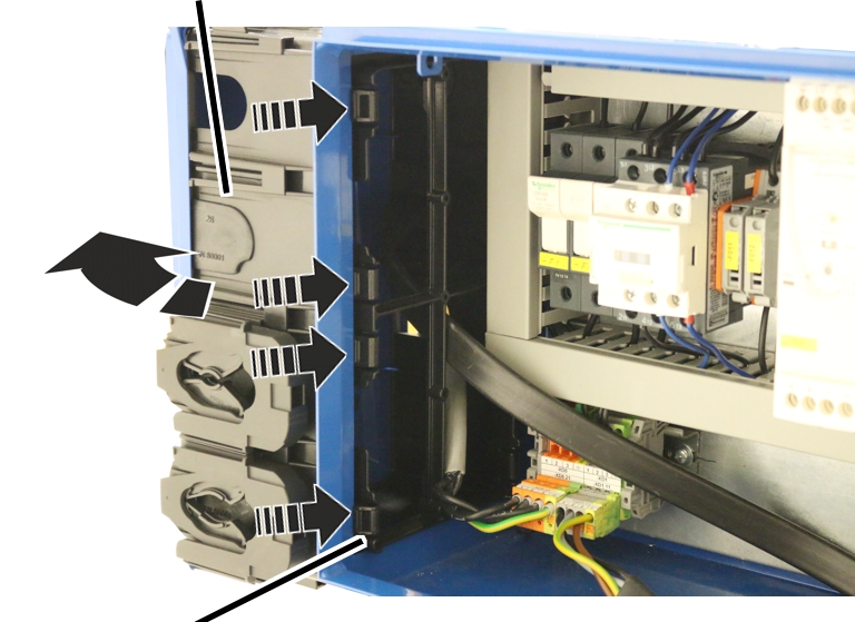
- Open the crane control cover.
- Press in the front four catches from the cable entry housing.
- Tip the cable entry housing backwards (in the direction of the rear of the panel).
- The cable entry housing is removed from the panel.
- Pull the cable entry housing forwards.
- The cable entry housing can hang loosely with the wiring on the crane control until the high-tensile bolts are tightened.
Attaching cable entry housing
Cable entry housing
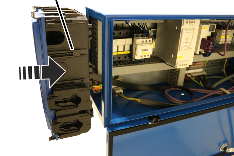
- Set the cable entry housing straight on the panel.
- Press the cable entry housing into the panel.
- Latch in the catches (8x) with a clicking sound.
Guiding the connection cables into the cable entry housing
During assembly, the connection cables are placed through the cable entry housing into the panel and connected. All connection cables can be plugged in. The cable bushings in the cable entry housing serve as seals.
The cable bushing (rubber) is sufficient for thinner round cables. For thicker round cables and flat cables, a three-piece cable strain relief is used in addition to the cable bushing to fix the connection cable in place.
Opening cable entry housing
Cable entry housing
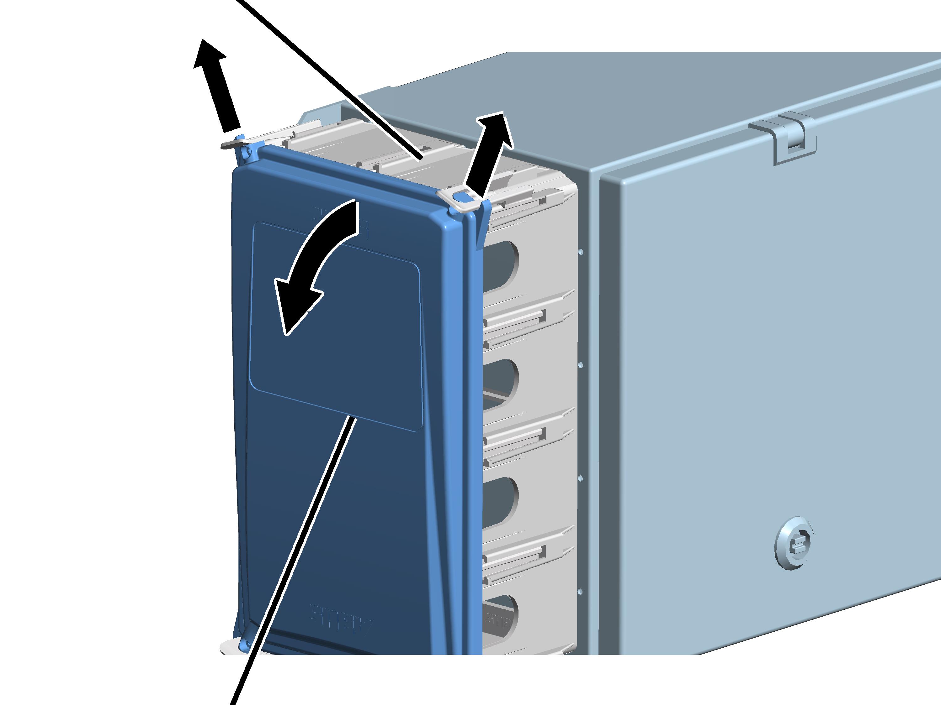
- Lightly push the two clip fasteners at the top outwards.
- At the same time, pull the upper part of the cover away from the housing.
- Tilt the cover downwards until it is almost horizontal.
- The cover will be automatically released from the lower clip fasteners when it is tilted.
Tip:
If the cover cannot be tipped downwards due to space limitations, its upper and lower clip fasteners can also be pressed slightly outwards and the cover can then be simply taken off.
Preparing connection cable
Connection cable
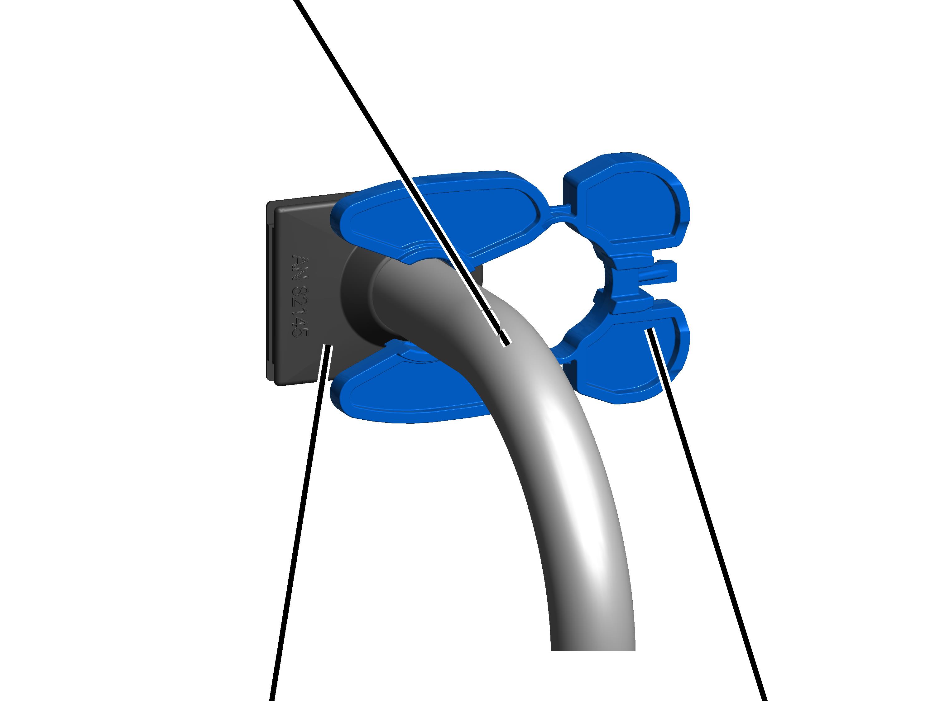
- Push the connection cable through the cable bushing until the connection cable can be guided up to the terminal block in the panel.
Depending on the line, the cable bushing has different openings (thick and thin round cables, flat cables) or is slotted.
- Connect the cable locking latch to the connection cable from outside.
Plugging in connection cable
Connection cable with cable locking latchCable strain relief base unit
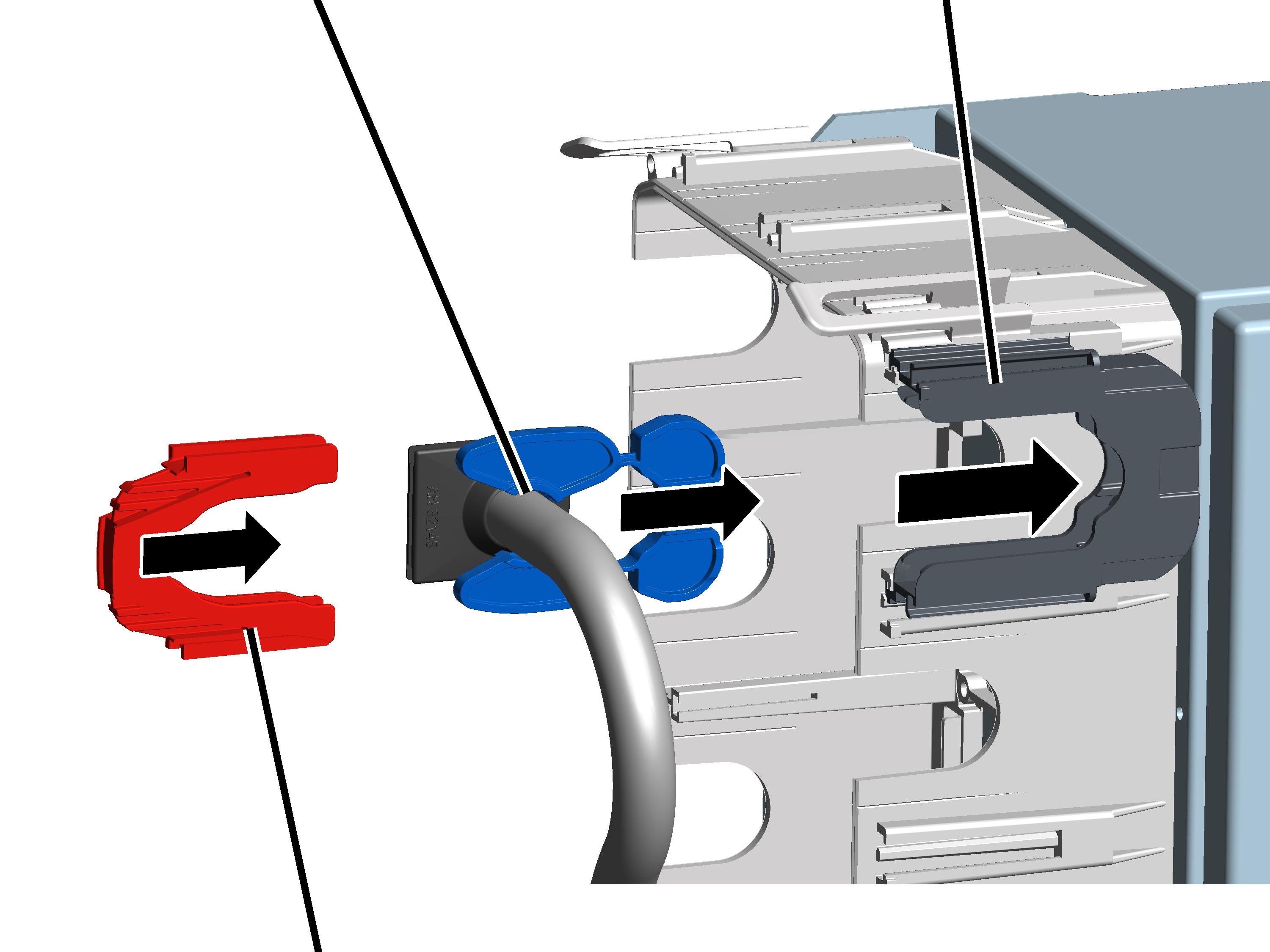
- Put the cable strain relief base unit into the cable entry housing and latch it in.
- Push the connection cable with the cable locking latch into the base unit and simultaneously guide the cable bushing (rubber) into the opening in the cable entry housing.
- Connect the cable strain relief clamping bracket to the base unit.
Secure cable bushing
Opening for cable ties
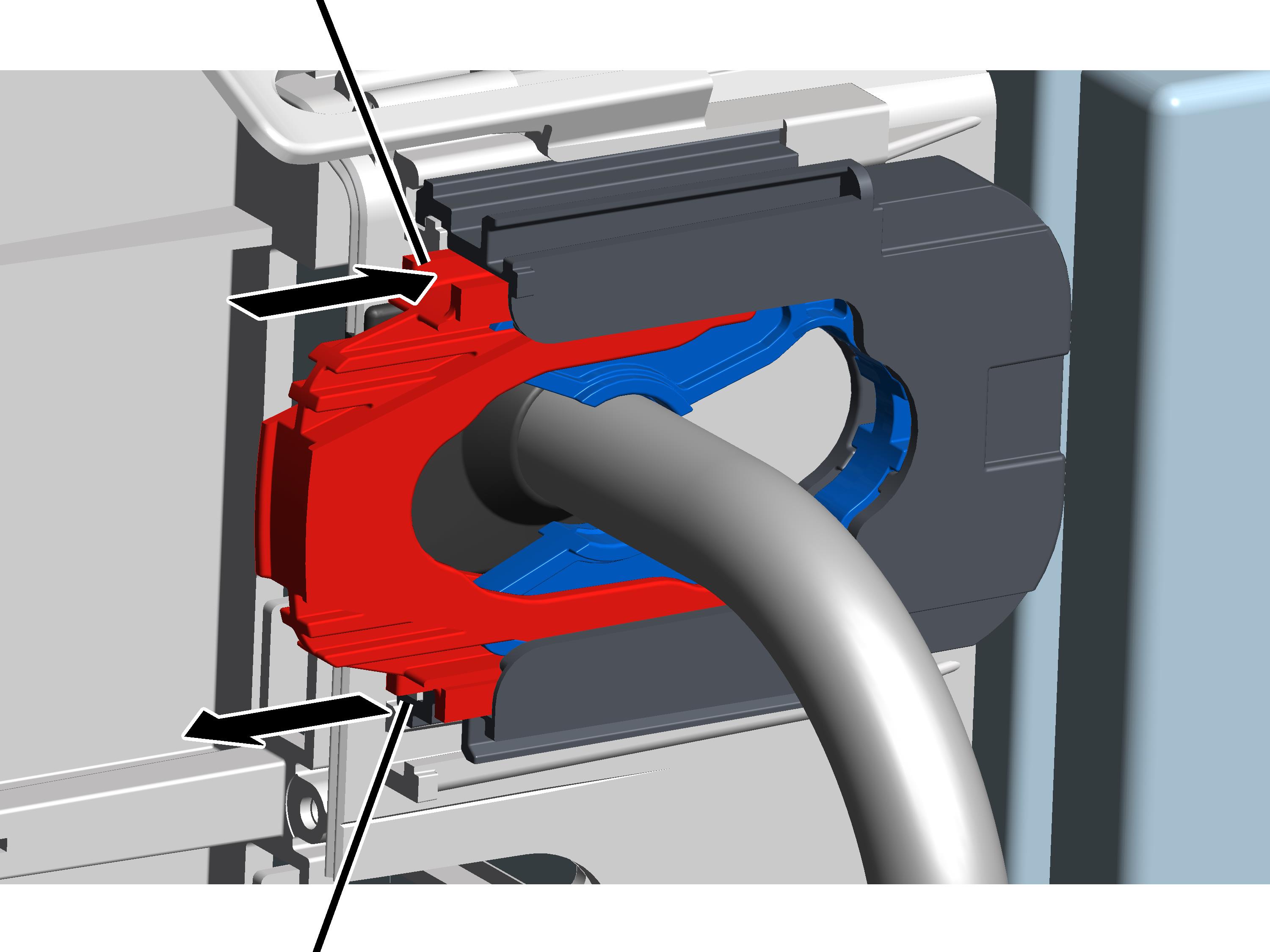
- Push the cable ties (not in the figure) into the opening on the cable strain relief.
- The cable tie is guided along the cable strain relief basic unit and comes out again at the other opening.
- Put the cable ties together and hand-tighten them.
Installing cable duct
Cable strain relief base unitCable duct
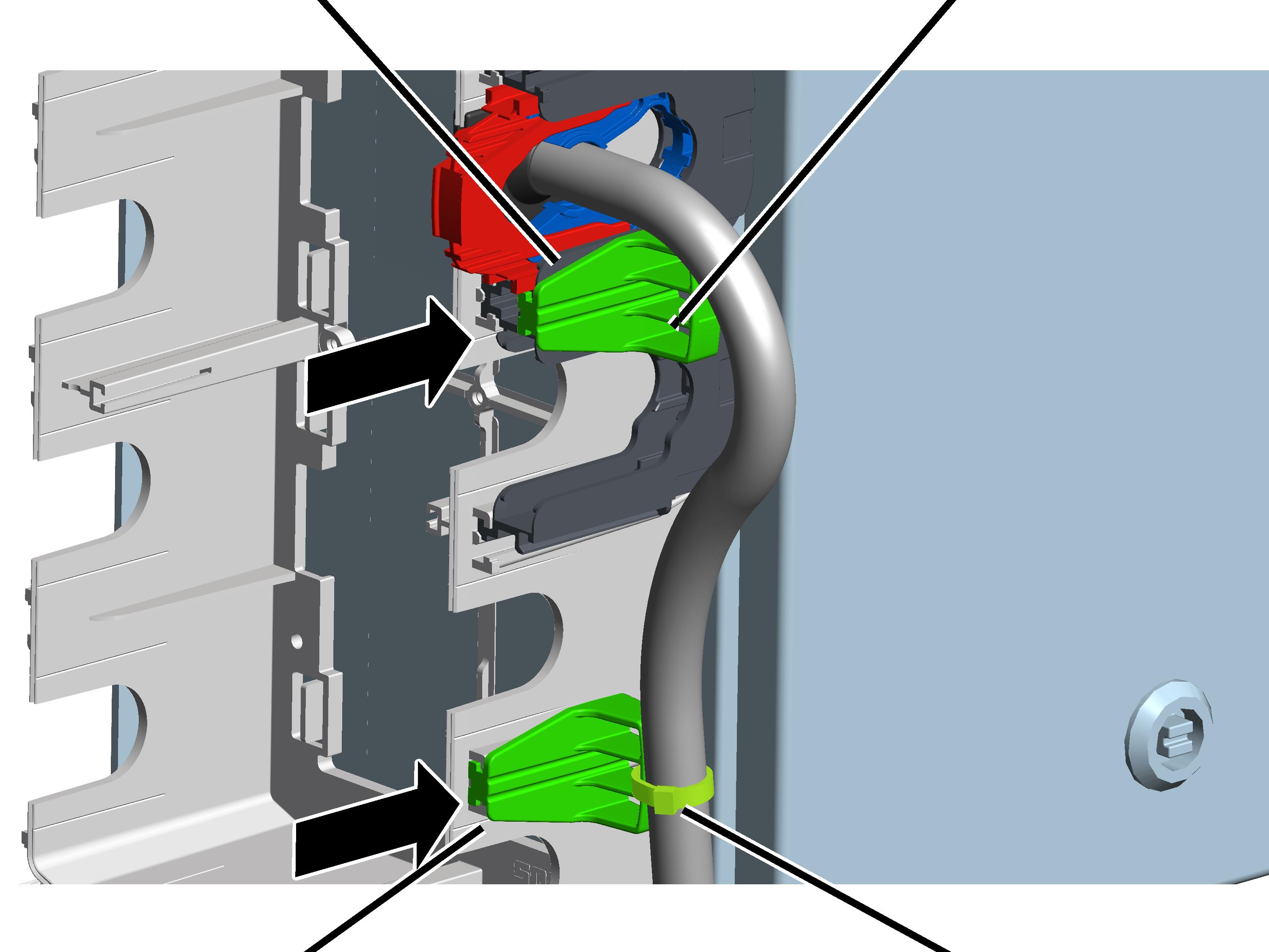
- Push the cable duct into the rail on the cable entry housing (below in the figure)
or
Push the cable duct into the rail between two cable strain relief base units (above in the figure).
- Attach the connection cable onto the cable duct with cable ties.
Closing cable entry housing
Clip fastener
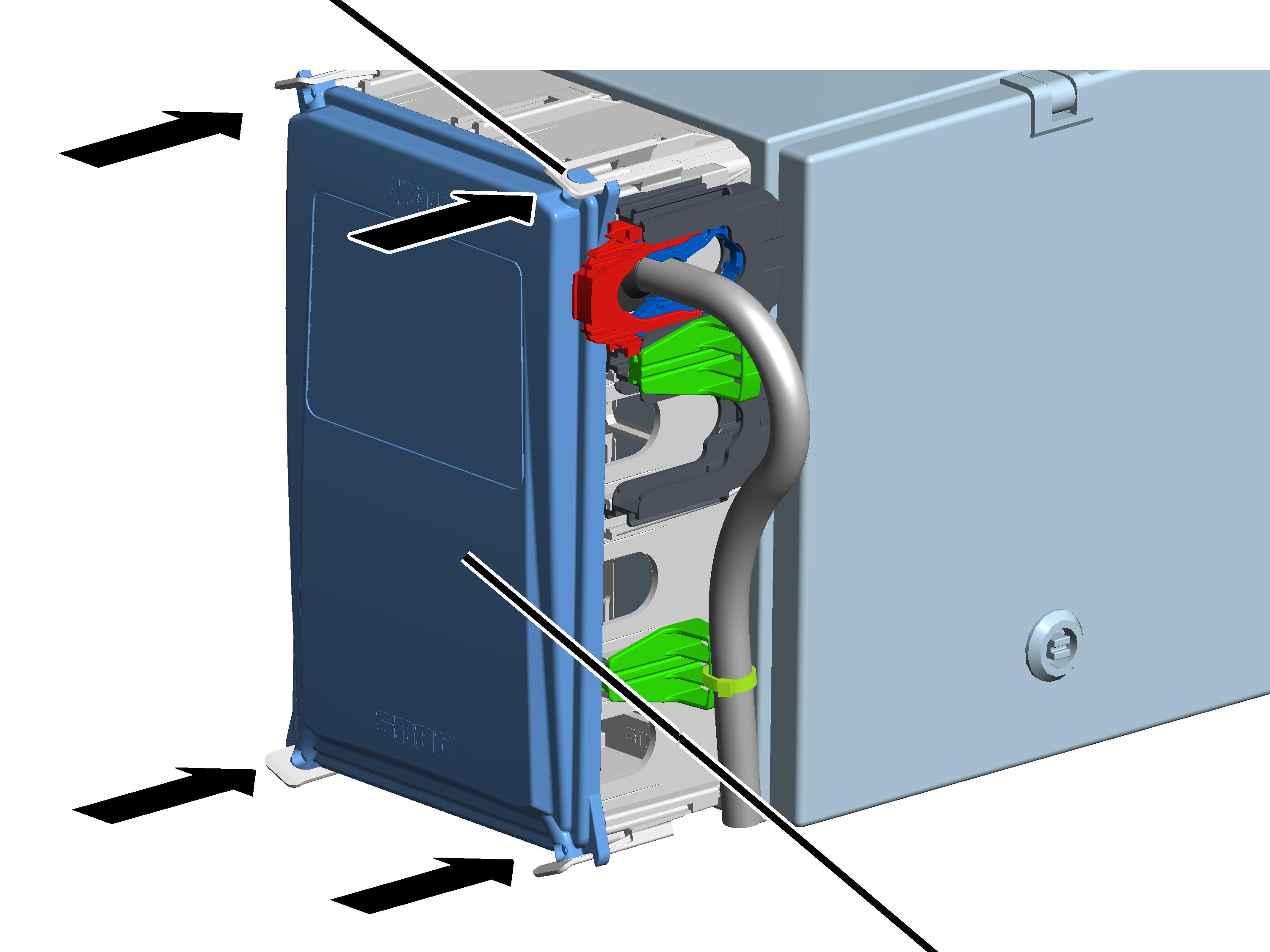
- Place all four corners of the cover onto the housing.
- Clip the cover into all four clip fasteners at the same time.
Setting switching point for the bottom hoist limiter
The wire rope hoist has a gear limit switch with three switching points. The backup limiter and the top hoist limiter are set at the factory. The bottom hoist limiter must be set on site.
Lowering the load hook to the lowest hook position
- Lower the load hook to the desired lowest hook position.
- The load hook should not touch the floor of the building.
- The wire rope should not be slack.
- A certain minimum clearance must be maintained between the cable guide and the drum housing. This clearance is determined in the next work step.
- The hook path (distance between the highest hook position [= hook headroom, dimension C] and the lowest hook position) must not be greater than is specified on the type plate.
Only with wire rope hoists with one cable guide
Cable guide
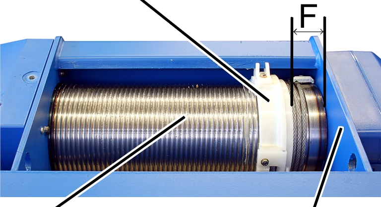
- Measure the distance 'F' between the cable guide and the drum housing and compare this with the table.
Wire rope hoist |
Type |
Reeving |
Distance 'F' |
|---|---|---|---|
GM 800 |
E, D, DA |
4/1 |
42 ± 2 |
GM 1000 |
E, D, |
4/1 2/1 |
56 ± 2 |
GM 2000 |
E, D, |
4/1 2/1 |
59 ± 2.5 |
GM 3000 |
E, D, |
4/1 2/1 |
73 ± 2.5 |
GM 5000 |
E, D, DA, DQA |
4/1 2/1 |
87.5 ± 3 |
GM 5000 |
D |
4/2 |
73 ± 2.5 |
GM 5000 |
Z |
4/2 8/2 |
87.5 ± 3 |
GM 6000 |
E, D, DA, DQA |
4/1 2/1 |
102 ± 3 |
GM 6000 |
Z |
4/2 8/2 |
102 ± 3 |
GM 7000 |
D, DA, |
2/1 4/1 6/1 |
131 ± 4 |
GM 7000 |
D |
4/2 8/2 |
87 ± 3 |
GM 7000 |
Z, ZA |
4/2 6/2 8/2 10/2 |
131 ± 4 |
Only with wire rope hoists with two cable guides
Cable guide
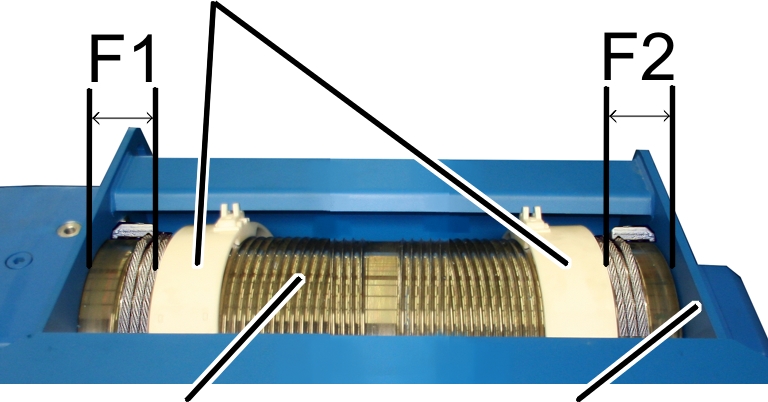
- Measure the distances 'F1' and 'F2' between the cable guides and the drum housing and compare these with the table.
Wire rope hoist |
Distance 'F1' |
Distance 'F2' |
|---|---|---|
GM 5000 - D |
80 ± 3 |
76 ± 3 |
GM 7000 - D |
84 ± 3 |
87 ± 3 |
- If necessary, raise the load hook until the distance 'F' or 'F1' or 'F2' is achieved.
Only with gear limit switch "GGS"
Detaching seal
Seal
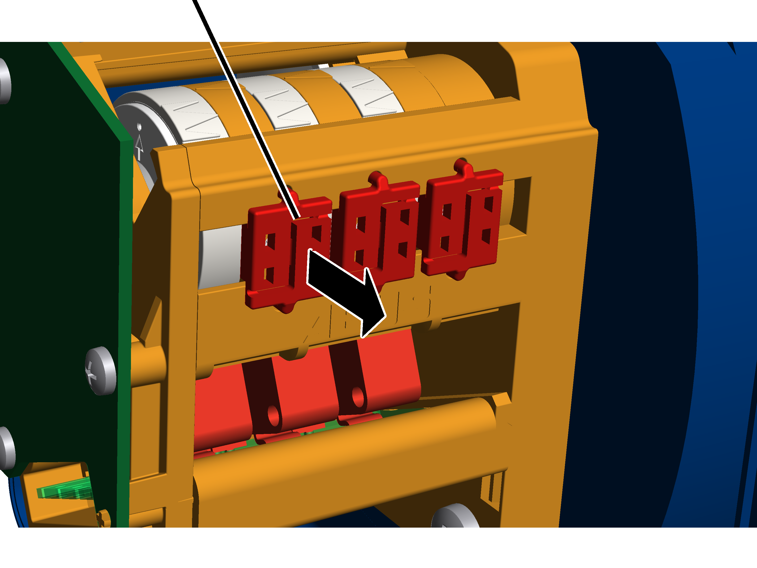
- Take off the housing cover of the hoist limit switch enclosure on the cable drum.
- Press the seal apart in the centre with a screwdriver and remove it.
Setting bottom hoist limiter
The bottom hoist limiter is set with the left adjusting screw.
White pointer of cam ringOrange pointer
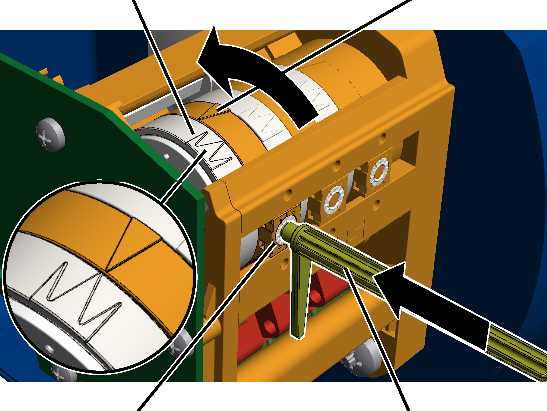
- Remove the adjusting key. It is fastened on two mounts on the gear limit switch.
Alternatively, a hexagon wrench key size 3.0 (ideally with rotary plate) can be used.
An electrically operated screwdriver may NOT be used.
- Press the adjusting key into the adjusting screw. Press it into the adjusting screw with light pressure.
- If necessary: Turn the adjusting screw until the white pointer of the cam ring lies to the right of the orange pointer. It should be neither to the left of the orange pointer nor exactly on it.
The middle white arrow shows the exact position of the switching point; the two white arrows to the left and right of it indicate the start and end of the switching phase (switching hysteresis).
- If necessary: Turn the adjusting screw until the white pointer of the cam ring lies to the right of the orange pointer. Continue turning until the white pointer lies exactly on the orange pointer and a clicking sound is audible.
- Turning to the right shifts the switching point downward.
- Turning to the left shifts the switching point upward.
- The switching point for the lowest hook position is now set. At this switching point the load hook stops during normal operation after it has previously braked. The braking distance is automatically determined by ABUControl in the next step.
Only with gear limit switch "GPK"
Setting bottom hoist limiter
The bottom hoist limiter is set with the foremost adjusting screw.
MicroswitchControl cam
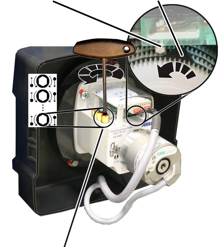
- Turn the foremost adjusting screw until the control cam is on the right of the Microswitch. It must not be on the left of the Microswitch or exactly on it.
- Turn the adjusting screw to the left until the control cam presses in an anti-clockwise direction against the Microswitch and an audible click is heard.
- The switching point for the lowest hook position is now set. At this switching point the load hook stops during normal operation after it has previously braked. The braking distance is automatically determined by ABUControl in the next step.
- The lowest hook position of the load hook has now been determined.
Determining braking distance
In normal operation, the load hook brakes at a slow lifting speed before it stops at the lowest hook position.
The braking distance is also determined automatically by ABUControl.
- Raise the load hook without load a few metres upwards.
- Lower the load hook with fast lifting speed downwards.
- The load hook stops at the lowest hook position.
Depending on how the switching point was changed, it may be that the load hook with fast lifting speed moves to the switching point and then suddenly stops there or that the load hook brakes earlier than is necessary and a long stretch moves only at slow lifting speed.
If the load hook has to travel a long way at slow lifting speed, the end position of the brake phase can be changed manually. See "Temporarily changing the end position of the brake phase of the hoist drive".
- ABUControl saves the new switching point of the lowest hook position and now calculates the necessary braking distance automatically.
During the next travel to the switching point:
- The load hook brakes (depending on the current lifting speed) shortly before the lowest hook position at slow lifting speed.
- The load hook only still travels with slow lifting speed immediately before the switching point.
- The load hook stops at the switching point.
Checking the setting
- Raise the load hook.
- Lower the load hook at both slow and fast lifting speed and check whether it halts at the lowest hook position.
Only with gear limit switch "GGS"
Sealing the adjusting screws
Seal
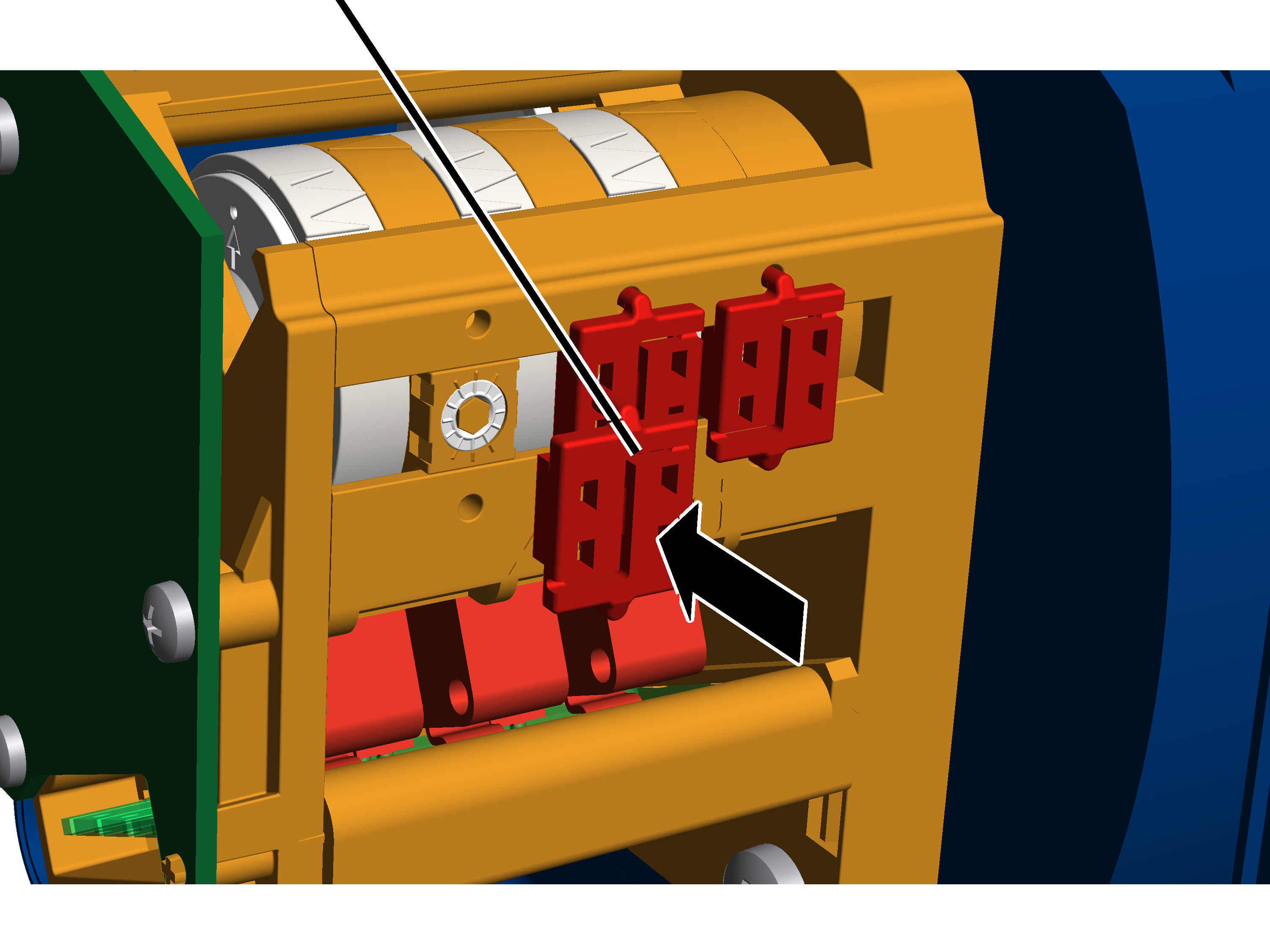
- Insert the seal on the adjusting screw and press it in.
Installing, setting and teaching-in distance sensor
With trolley travel distance sensors: The trolleys measure their distance from the end of the main girder in each case with a distance sensor laser beam. With this measurement, the braking function and shut-down can be implemented (instead of by the usual cross-type limit switch) and also the anti-collision device (instead of by the usual reflective light barriers) through the resulting calculated position of both trolleys. In the joint operation of both trolleys, the constant distance between the trolleys is also calculated and correspondingly controlled.
With crane travel distance sensor: The cranes measure their distance from another crane on the same run (or from both of the other cranes on the same run) via the distance sensor laser beam. This enables the braking function and the shut-down to the other crane/s on the same run to be implemented (instead of by the usual reflective light barriers). This also enables the constant distance to be controlled in tandem operation. The braking function and shut-down at the end of the crane track is implemented via the cross-type limit switch.
Reflective light barriers or one-way light barriers are generally used when there is a crane distancing system due to structural reasons or a load-dependent crane distancing system. Cross-type limit switches are generally used for building profile controls or an absolute value measuring system.
For this work step, access from a laptop or tablet computer to KranOS is necessary. The user "Service" (user level [2]) must be logged in.
Overview: Distance sensor and reflector
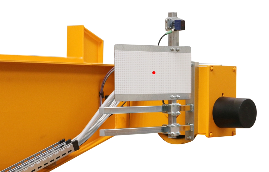
- With crane travel distance sensor: The distance sensor of the crane and the reflector for the distance sensor of another crane on the same run are fastened on a shared mount on the end carriage. On the other crane on the same run, the placement of distance sensor and reflector are accordingly interchanged. The light beams of the distance sensors are not allowed to cross each other.
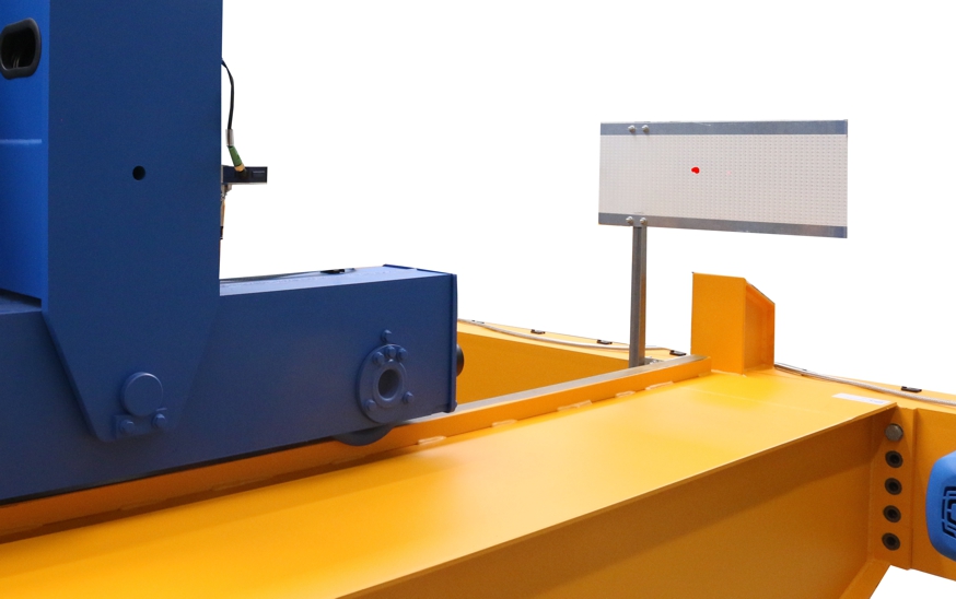
- With trolley travel distance sensor on the wire rope hoist GM modular: The distance sensor is pushed laterally onto a mount in the cover of the cable drum. The reflector is taped onto the end carriage of the crane as adhesive foil or fastened on a square tube.
- With trolley travel distance sensor on the wire rope hoist GM compact: The distance sensor is installed on the trolley frame with a magnetic mount. The reflector is taped onto the end carriage of the crane as adhesive foil or fastened on a square tube.
Installing distance sensor
The distance sensor is either fastened with a mount on a square tube on the end carriage or attached to the wire rope hoist with a magnetic mount.
Only with distance sensor on square tube
Installing the mount for the light barriers
Threaded bracket
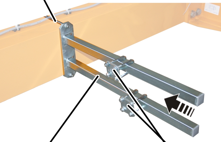
- Attach the mount on the end carriage.
- Bolt the mount onto the threaded bracket.
Threaded bracket |
Tightening torque |
|---|---|
M8 |
25 Nm |
M10 |
50 Nm |
M12 |
75 Nm |
- Slide on the two pipe clamps and secure them.
- Push the square tube in the pipe clamps and screw tight.
AdapterMounting plate
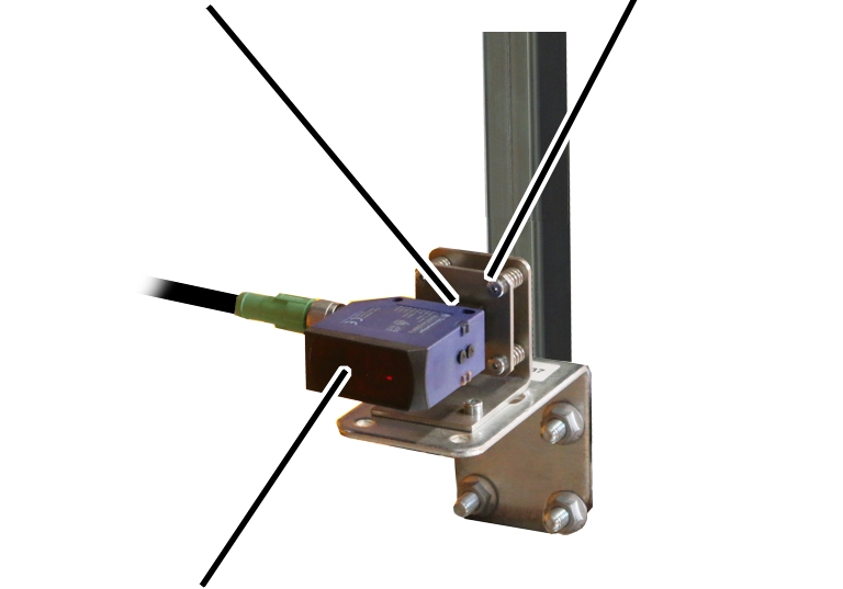
- Push the entire mount onto the square tube.
- Screw in the mount using M8 rib nuts (4x) and tighten by hand.
- Push the distance sensor into the adapter on the mounting plate and tighten the screws.
Only with distance sensor on magnetic mount
- Select the appropriate size and type from the following drawings.
- Read the dimensions A and B from the following tables.
Magnetic mount
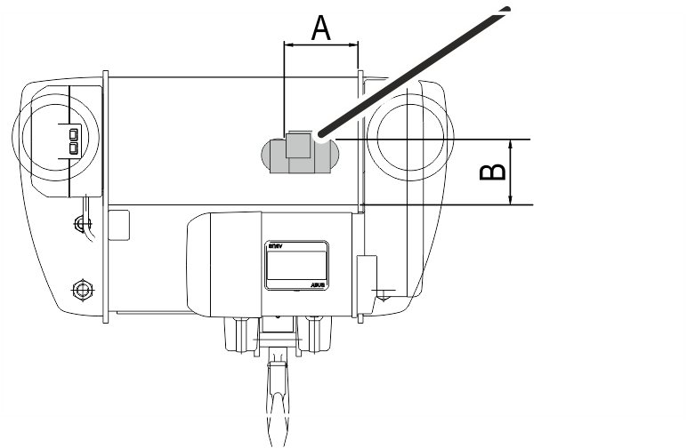
Assembly position of the magnetic mount on wire rope hoist E
Size |
Dimension A |
Dimension B |
|---|---|---|
800 4/1 |
130 |
100 |
1000 2/1 |
130 |
130 |
1000 4/1 |
130 |
130 |
2000 2/1 |
130 |
130 |
2000 4/1 |
130 |
160 |
3000 2/1 |
130 |
160 |
3000 4/1 |
130 |
160 |
5000 2/1 |
130 |
160 |
5000 4/1 |
130 |
200 |
6000 2/1 |
130 |
160 |
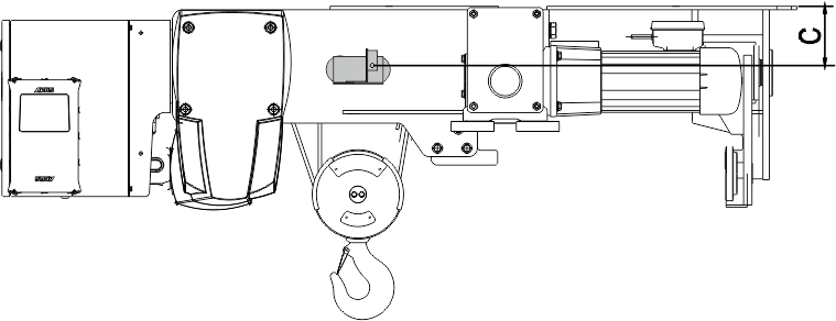
Assembly position of the magnetic mount on wire rope hoist S. Observe dimension C and fasten the distance sensor as centred as possible on the rope drive.
Size |
Dimension A |
|---|---|
800 4/1 |
140 |
1000 4/1 |
180 |
2000 4/1 |
180 |
3000 2/1 |
180 |
3000 4/1 |
245 |
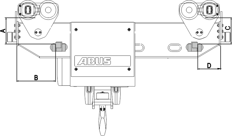
Assembly position of the magnetic mount on wire rope hoist U. Observe the different positions for the left and right distance sensor.
Size |
Dimension A |
Dimension B |
Dimension C |
Dimension D |
|---|---|---|---|---|
5000 4/1 |
330 |
350 |
310 |
660 |
6000 2/1 |
325 |
640 |
285 |
560 |
6000 4/1 |
400 |
320 |
370 |
595 |
7000 2/1 |
360 |
420 |
450 |
550 |
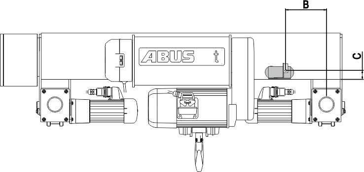
Assembly position of the magnetic mount on wire rope hoist D.
Size |
Dimension A |
Dimension B |
|---|---|---|
800 4/1 |
210 |
60 |
1000 4/1 |
200 |
50 |
2000 2/1 |
200 |
50 |
2000 4/1 |
200 |
50 |
3000 2/1 |
225 |
50 |
3000 4/1 |
225 |
50 |
5000 2/1 |
200 |
50 |
5000 4/1 |
130 |
50 |
5000 4/2 |
200 |
50 |
5000 6/1 |
130 |
50 |
6000 2/1 |
200 |
45 |
6000 4/1 |
170 |
50 |
6000 6/1 |
200 |
50 |
7000 2/1 |
190 |
50 |
7000 4/1 |
190 |
50 |
7000 4/2 |
190 |
50 |
7000 6/1 |
190 |
60 |
7000 8/2 |
190 |
50 |
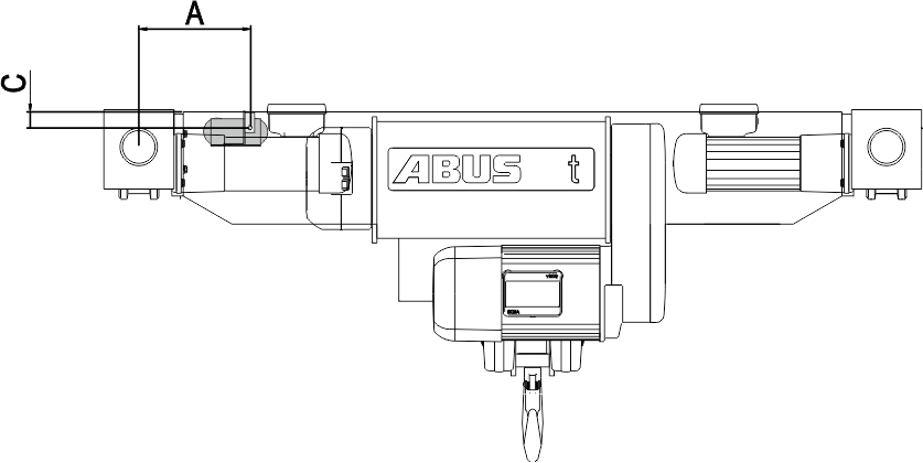
Assembly position of the magnetic mount on wire rope hoist DA.
Size |
Dimension A |
Dimension C |
|---|---|---|
800 4/1 |
540 |
30 |
1000 4/1 |
250 |
35 |
2000 2/1 |
520 |
55 |
2000 4/1 |
520 |
55 |
3000 2/1 |
470 |
50 |
3000 4/1 |
550 |
60 |
5000 2/1 |
550 |
45 |
5000 4/1 |
610 |
55 |
6000 2/1 |
565 |
50 |
6000 4/1 |
700 |
55 |
7000 2/1 |
590 |
70 |
7000 4/1 |
390 |
170 |
7000 6/1 |
350 |
200 |
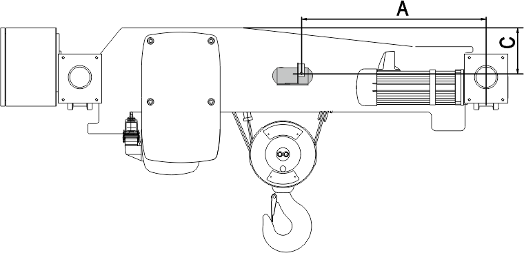
Assembly position of the magnetic mount on wire rope hoist DQA. Observe dimension C and fasten the distance sensor as centred as possible on the rope drive.
Size |
Track |
Dimension C |
|---|---|---|
2000 |
1400 |
100 |
3000 |
1400 |
85 |
2000 |
1600 |
100 |
3000 |
1600 |
85 |
5000 |
1600 |
75 |
6000 |
1600 |
80 |
2000 |
2000 |
95 |
3000 |
2000 |
85 |
5000 |
2000 |
75 |
6000 |
2000 |
85 |
2000 |
2500 |
100 |
3000 |
2500 |
80 |
5000 |
2500 |
75 |
6000 |
2500 |
85 |
7000 |
2500 |
100 |
7000 |
3000 |
100 |
7000 |
3500 |
100 |
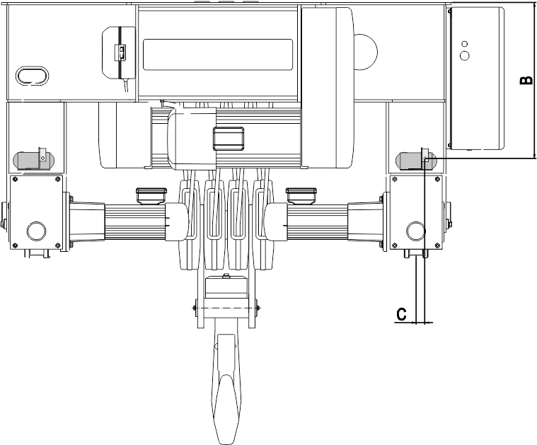
Assembly position of the magnetic mount on wire rope hoist Z.
Size |
Dimension B |
|---|---|
5000 4/2 |
535 |
5000 8/2 |
580 |
6000 4/2 |
565 |
6000 8/2 |
570 |
7000 4/2 |
725 |
7000 6/2 |
850 |
7000 8/2 |
660 |
7000 10/2 |
300 |
7000 12/2 |
470 |
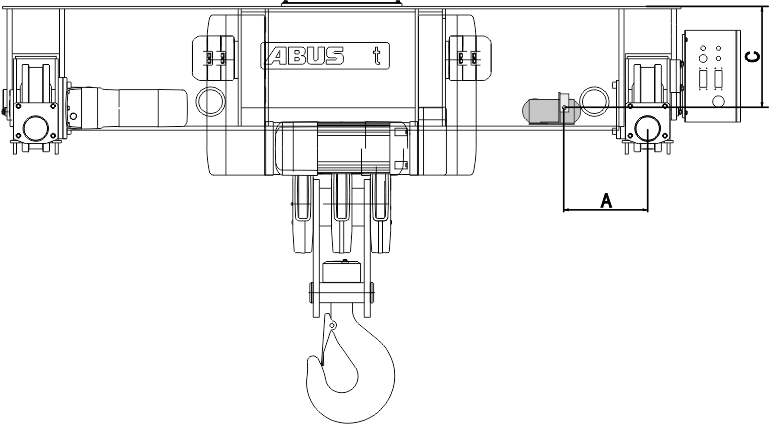
Assembly position of the magnetic mount on wire rope hoist ZA.
Size |
Dimension A |
Dimension C |
|---|---|---|
5000 8/2 |
315 |
355 |
6000 8/2 |
315 |
200 |
7000 6/2 |
440 |
500 |
7000 8/2 |
420 |
482 |
7000 10/2 |
500 |
570 |
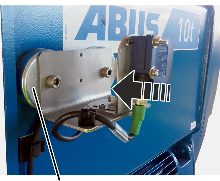
- Attach the magnetic mount to the wire rope hoist.
The position specified refers to the point on the distance sensor at which the laser beam emerges from it.
Depending on the installation situation, the position for the magnetic mount may already be marked.
Only with wire rope hoist GM modular
Drum side
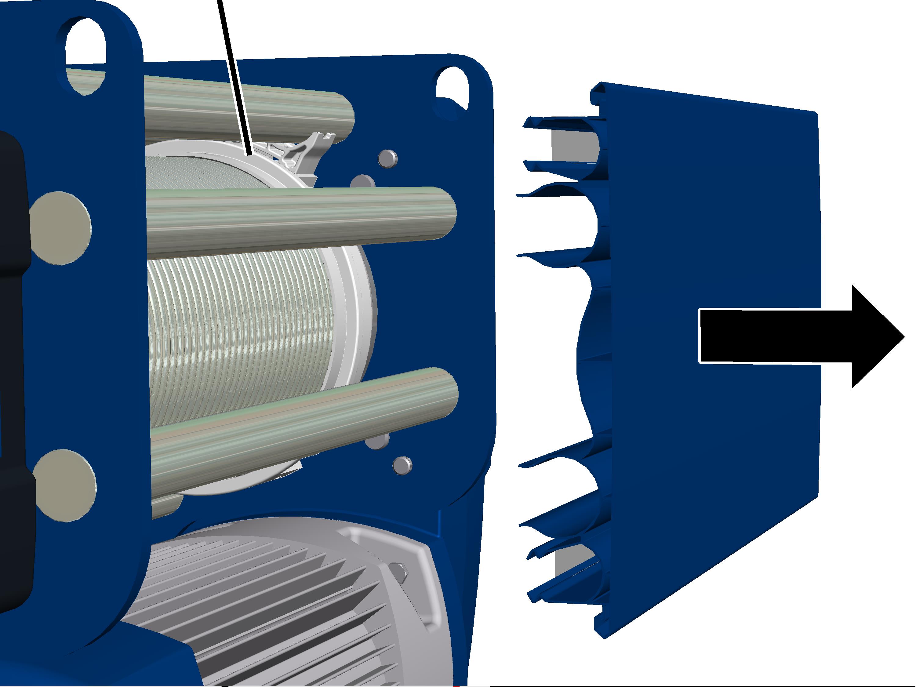
- Pull off the cover from the drum side.
Angle plate
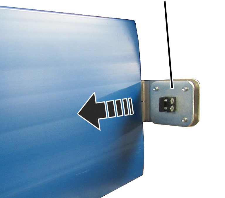
- Push the angle plate with the slit laterally into the cover.
- Place the cover on the wire rope hoist.
- Push the distance sensor into the adapter on the mounting plate and tighten the screws.
Installing reflector
- During tandem control: Put the cranes at maximum distance.
- During the joint operation of two trolleys: Put trolleys at maximum distance.
Only with reflector as adhesive foil
- Move the reflector as adhesive foil so that the laser point is as close to centred as possible.
The more precise adjustment is done later on the distance sensor. The position of the adhered adhesive foil can no longer be corrected.
- Press on the adhesive foil.
Only with reflectors on a square tube
Threaded bracket
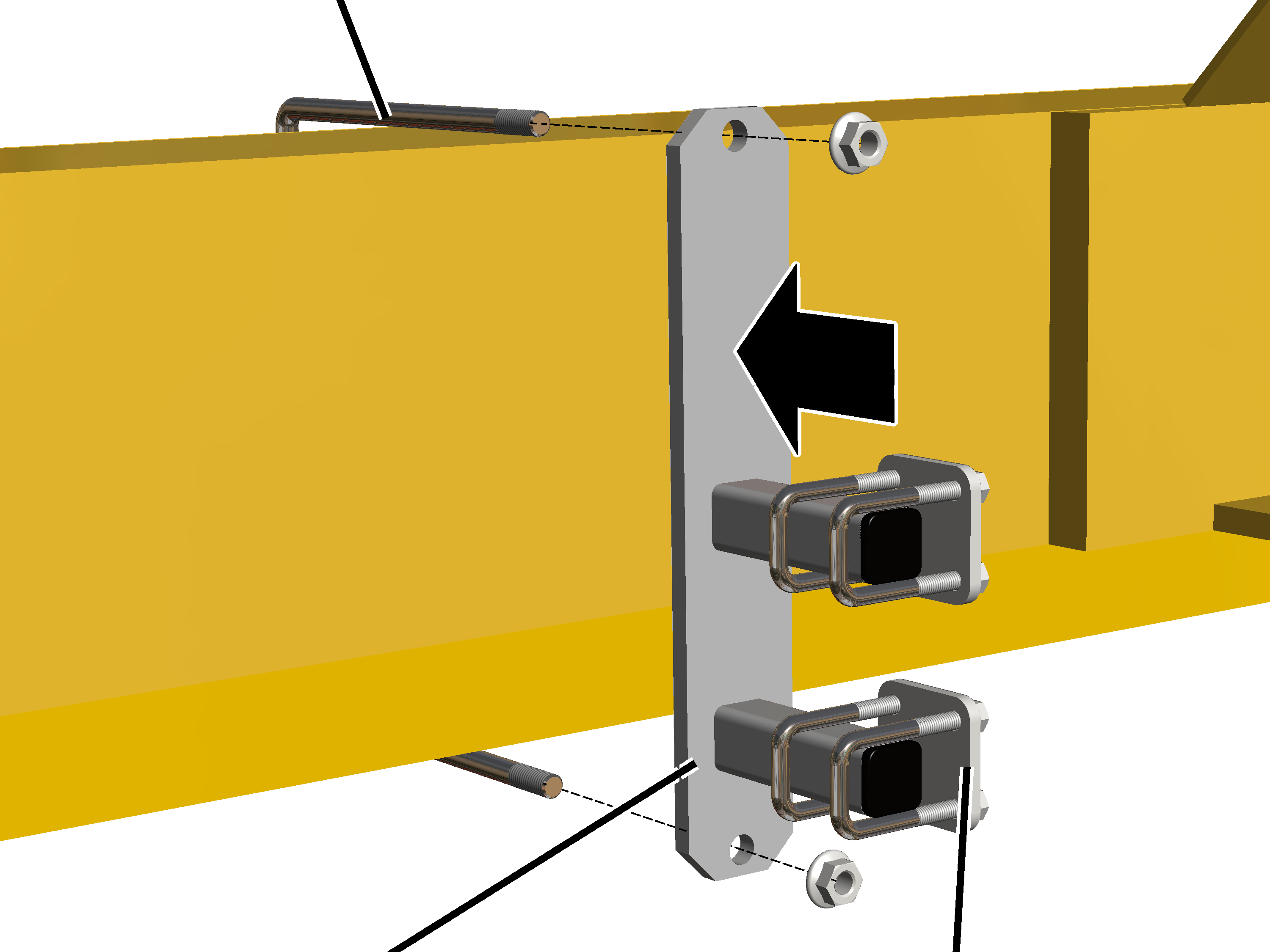
- Bolt the mount onto the threaded bracket.
Threaded bracket |
Tightening torque |
|---|---|
M8 |
25 Nm |
M10 |
50 Nm |
M12 |
75 Nm |
- Slide on the two pipe clamps and secure them.
Square tube
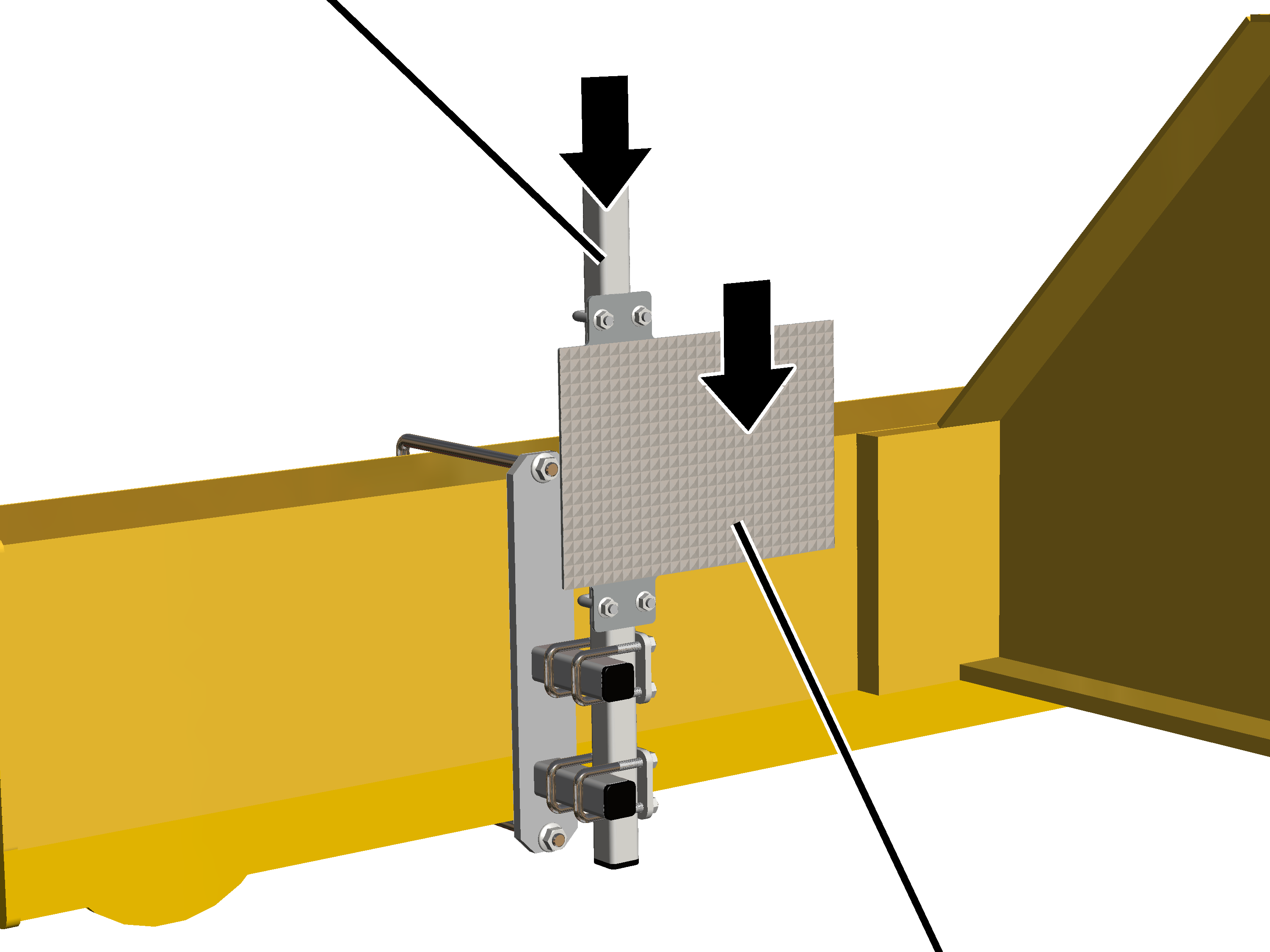
- Push the square tube in the pipe clamps.
- Push the reflector onto the square tube.
- Move the reflector so that the laser point is as close to centred as possible.
The more precise adjustment is done later on the distance sensor.
- Screw on the pipe clamps and reflector using M8 rib nuts (4x) and tighten by hand.
Setting distance sensor
Only with mount
Fillister-head screw M6x20
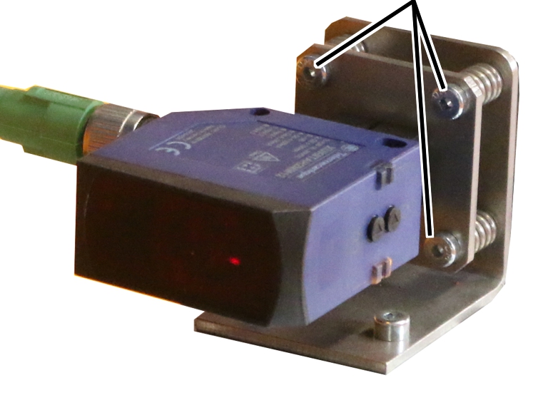
- Adjust the distance sensor with M6x20 fillister-head screws (3x) so that the laser point is exactly on the centre of the reflector.
- If the distance sensor receives the laser beam reflected from the reflector, the LEDs on the distance sensor light up.
- If the distance sensor does not receive the laser beam, one of the LEDs flashes.
Only with magnetic mount
Adjust the distance sensor with the rough and fine adjustment screws so that the laser point is exactly in the centre of the reflector.
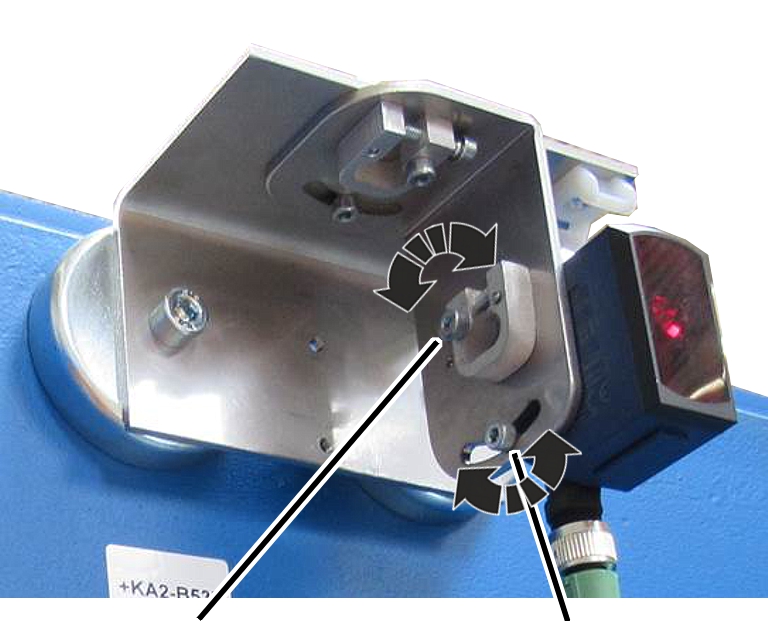
- Release the fillister-head screw in the elongated hole for the rough adjustment and tilt the distance sensor.
- If necessary, release the fillister-head screw for the fine adjustment and fine-adjust the distance sensor with the short, crosswise-lying fillister-head screw.
- If the distance sensor receives the laser beam reflected from the reflector, the LEDs on the distance sensor light up.
- If the distance sensor does not receive the laser beam, one of the LEDs flashes.
- Tighten the long fillister-head screws (2x).
- Travel along the entire traversing range with the crane (or the trolley) and check whether the laser beam meets the reflector at every position and does not drift laterally or upwards/downwards.
Opening the distance sensor settings
Overview: Navigation in KranOS |
|---|
User "SERVICE" 🡪 "Crane travel" 🡪 "Crane travel distance sensors" |
User "SERVICE" 🡪 "Trolley travel" 🡪 "Trolley travel distance sensors" |
- Log in to KranOS with user "Service" (user level [2]). See "Logging into and registering in KranOS".
- Select the desired trolley drive or crane travel drive (e.g. trolley travel 1 or crane travel) in the main menu.
- The window for the requested drive appears.
- Click on the "Crane travel distance sensors" (or "Trolley travel distance sensors") menu item in the "Settings" menu (three horizontal bars).
Teaching-in distance sensor
Now the distance sensor will be taught in. For this purpose, the crane/trolley is travelled to the desired position and the distance sensor value determined for this position is saved in ABUControl.
"Teach-in mode" button
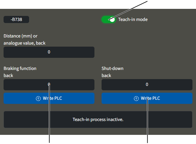
- Click on "Teach-in mode" button.
- The button's background turns green.
- "Teach-in mode" is switched on.
- The notice "Overriding limit switch" is displayed.
It is possible that switching points for braking function and shut-down already saved will now be ignored.
Thus, the trolley (the crane) can be moved to any new positions.
- A message appears for which switching point (braking function or shut-down) is to be travelled to.
- Travel the trolley (the crane) to the corresponding position.
The distance sensor must be at least 0.35 m away from the reflector.
- In the column for the switching point which is to be learnt: Click on the "Write PLC" button.
- The measured value for the current position is displayed in the description field.
The displayed value is a measured value without measurement unit, which is used to calculate the position later.
- Repeat the process for all further switching points.
After the switching points have been saved:
- The teach-in mode ends automatically.
- The limit switch bridging turns off automatically.
Calibrating the load measuring system with an increased test load
The load measuring system continuously determines the current load on the load hook. This value is necessary for many crane functions, especially for the overload protection.
The load measuring system must be calibrated once with an increased test load in order for the attached load to be evaluated.
For this work step, access from a laptop or tablet computer to KranOS is necessary. The user "Service" (user level [2]) must be logged in.
Requirements for the calibration:
- A test load is necessary for the calibration.
- The dimensions of the test load must be known exactly.
- The dimensions of the test load should if possible correspond to the maximum load capacity of the crane or the trolley, or it should lie as close as possible to the maximum load capacity of the crane or the trolley.
For the dynamic test of the maximum load capacity of the crane a test load of 110% of the maximum load capacity of the crane is usually used. In general, this can also be used for the calibration.
A load above the maximum load capacity of the crane may only be lifted by a qualified person for the test before the first commissioning of crane installations.
ABUControl blocks the lifting function for loads over 110% of the maximum load capacity of the crane. The load can no longer be lifted and can only be set down instead.
Opening hoist calibration
Overview: Navigation in KranOS |
|---|
User "SERVICE" 🡪 "Hoist" 🡪 "Hoist calibration" |
- Log in to KranOS with user "Service" (user level [2]). See "Logging into and registering in KranOS".
- Select the desired hoist (e.g. hoist 1) in the main menu.
- The window for the requested hoist appears.
- Click on the "Hoist calibration" menu item in the "Settings" menu (three horizontal bars).
Selecting load measuring channels
The area in the left of the "Hoist calibration" window is used for the calibration with an increased test load. Whereas the "Calibrating load sensor" button is only needed if the fixed point crosshead or the load sensor was replaced.
Test load input field"Calibrating load sensor" button
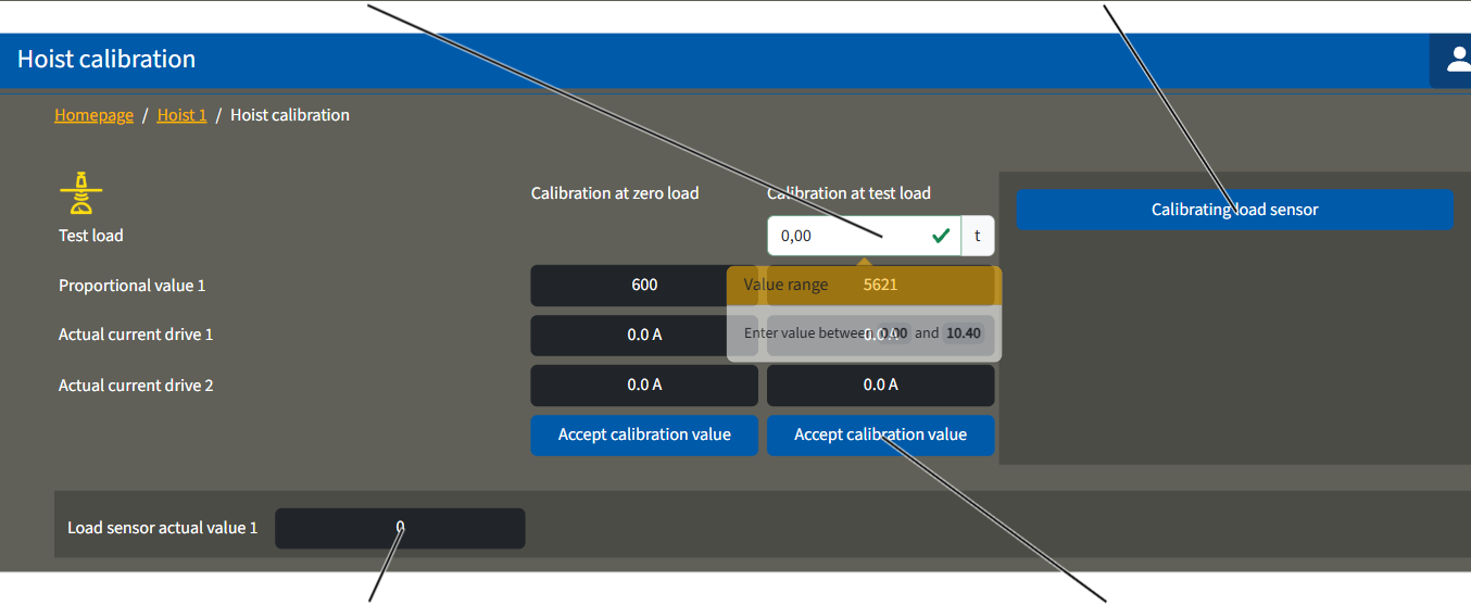
- The "Hoist calibration" window appears.
- The currently measured value is displayed and constantly updated in the "Load sensor actual value" field.
The current values in the "Proportional value" and "Load sensor actual value" lines are measured values without measurement units, which are later used to calculate the load.
Calibrating zero load
- If necessary: Take the load and lifting tackle out of the load hook.
- Lift/lower the empty load hook so that it hangs relatively far up, e.g. about a metre under the highest hook position.
This ensures the weight of the unwound wire rope is not included in the measurement.
Measured proportional value
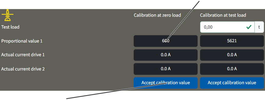
- Click on the "Accept calibration value" button in the "Calibration at zero load" column.
- The current value is saved as the "zero load" and displayed in the "Proportional value" field in the column "Calibration at zero load".
Calibrating test load
"Test load" input field
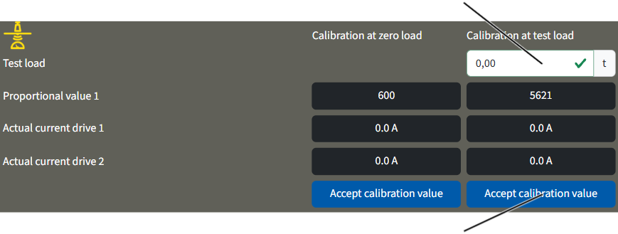
- Click on the "Test load" input field in the "Calibration at test load" column.
- Input the test load dimensions.
- The input value is accepted.
- Observe the applicable occupational health and safety regulations and lift the test load.
- Wait until the test load hangs calmly in the load hook.
- Click on the "Accept calibration value" button in the "Calibration at test load" column.
- The value determined at the current test load is saved. The value displayed in the "Proportional value" field in the "Calibration at test load" column refers to the crane's rated load. If the crane has been calibrated with a test load that is lower than the rated load, the value displayed in the "Proportional value" field is extrapolated to the rated load. The value displayed in the "Proportional load" field is then higher than the value in the "Actual load sensor value" field.
Bridging overload protection
For testing, a static test with 1.25 times the weight of the maximum load capacity of the crane and a dynamic test with 1.1 times the weight of the maximum load capacity of the crane must be carried out before the first commissioning.
The overload protection of the crane must also be bridged.
If a load weighing more than 110% of the maximum load capacity is lifted:
- The overload protection of the crane triggers.
- The load cannot be lifted any further.
- The load hook can only be lowered.
If the overload protection is bridged after having been triggered at a load more than 110%:
- The load can now be lifted further.
- If the load reduces to under 100% of the maximum load capacity, the load can again be directly lifted and lowered without bridging the overload protection.
Bridging overload protection
Bridging overload protection by coupling:
Prong terminal block ‑X103
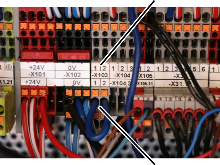
- Open trolley control.
- Search for prong terminal block ‑X103.
- Connect the double-pole coupling with jumper into the prong terminal block.
A suitable coupling with jumper can be found in the documentation folder/test log book of the crane.
- The overload protection is now bridged.
With LED matrix display: The message "F0021: Overload protection bridged" is shown.
- After 15 minutes: The overload protection is automatically switched on again.
With LED matrix display: The message "F0022: Overload protection bridged: Time exceeded" is shown.
If the overload protection is to be bridged again, the coupling must first be removed and then plugged in again.
If the coupling has a jumper inserted and ABUControl is restarted, the overload protection is not automatically bridged. Instead, the message "F0023: Overload protection: remove bridging" is displayed.
The overload protection is only bridged if the coupling is inserted with a jumper with the crane switched on.
Bridging overload protection by KranOS:
Overview: Navigation in KranOS |
|---|
User "SERVICE" 🡪 "Hoist" |
- Log in to KranOS with user "Service" (user level [2]). See "Logging into and registering in KranOS".
- Select the desired hoist (e.g. hoist 1) in the main menu.
- The window for the requested hoist appears.
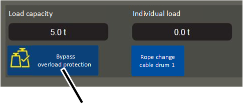
- Click the button "Bypass overload protection".
- The button's background turns red.
- The overload protection is now bridged.
- After 15 minutes: The overload protection is automatically switched on again.
If the overload protection is to be bridged again afterwards, the button must be clicked again.
Reactivating overload protection
As soon as the static and dynamic tests have ended:
- Remove the coupling from the prong terminal block-X103.
or
Click the button "Bypass overload protection".
- The overload protection is switched on again.
- The button's background is no longer red.
- Press the emergency stop button and unlock again.
or
Press the horn.
- The fault message is thus activated on ABUControl.
Installing light barrier for signal transmission for load-dependent crane distancing system
For a load-dependent crane distancing system, it must be known in both controls (in the crane and the other crane on the same run) whether the set load has fallen below or been exceeded on the other crane. This information is transmitted between the cranes via a light barrier. Each crane has light barriers for signal transmission; one as a transmitter and one as a receiver.
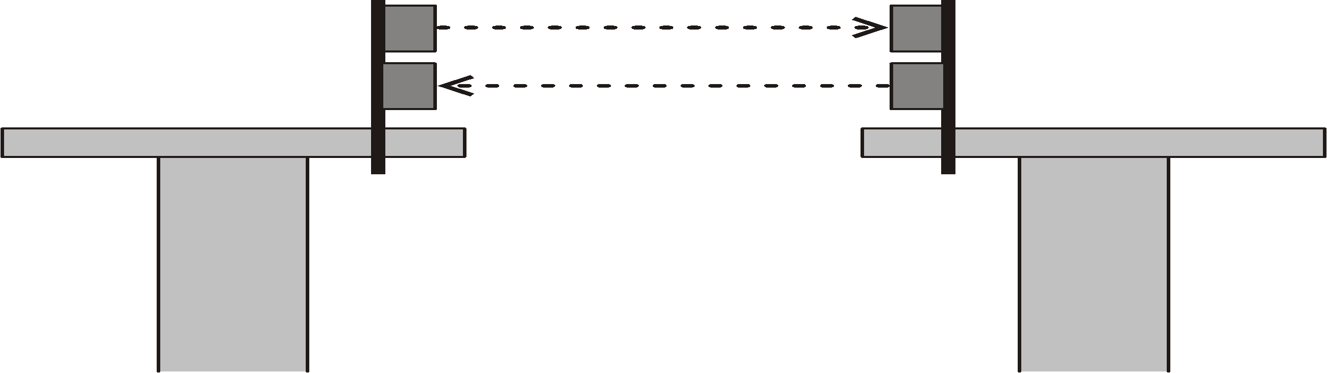
- The light barriers for transmitting the release signal are installed on opposite ends of the end carriages of the cranes.
- One transmitter and one receiver is installed on each crane.
- The transmitter is installed above and the receiver below on a crane. It is the other way around on the other crane.
Installing the mount for the light barriers
Threaded bracket
- Attach the mount to opposite ends of the end carriages.
- Bolt the mount onto the threaded bracket.
Threaded bracket |
Tightening torque |
|---|---|
M8 |
25 Nm |
M10 |
50 Nm |
M12 |
75 Nm |
- Slide on the two pipe clamps and secure them.
Only with vertically arranged light barriers
Mount for the light barriers
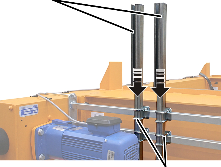
- Push the mount for the light barriers (2x) into the pipe clamps.
- Align the mounts and hand-tighten the pipe clamps.
Installing the light barriers
Light barriers
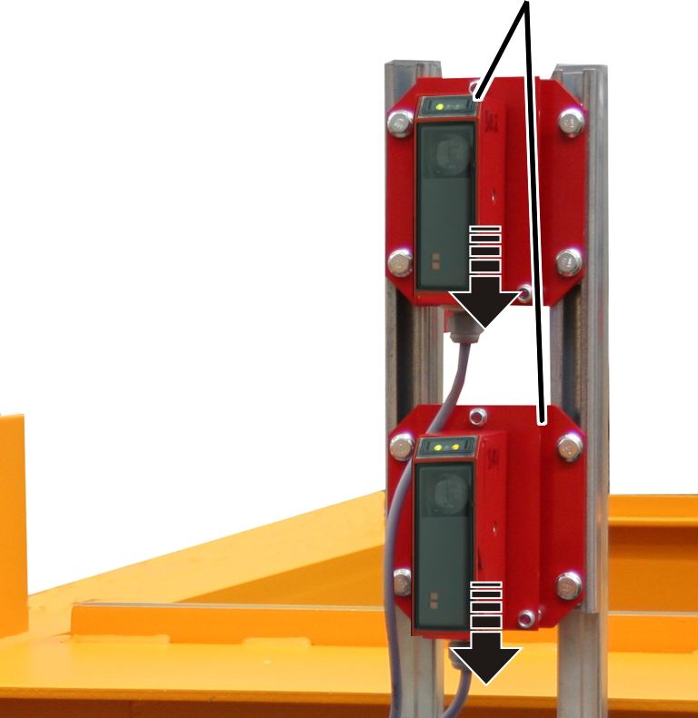
- Push light barriers into the mounts.
- Screw the light barriers until hand-tight.
- Route the light barrier connection cables to the crane panel and secure with cable clips.
Only with horizontally arranged light barriers
If there is little space due to the lower installation height of the crane over the main girder, the light barriers can be installed side-by-side with additional mounts rather than above one another.
Mount for the light barriers
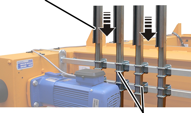
- Push the mount for the light barriers (4x) into the pipe clamps.
- Align the mounts and hand-tighten the pipe clamps.
Installing the light barriers
Light barriers
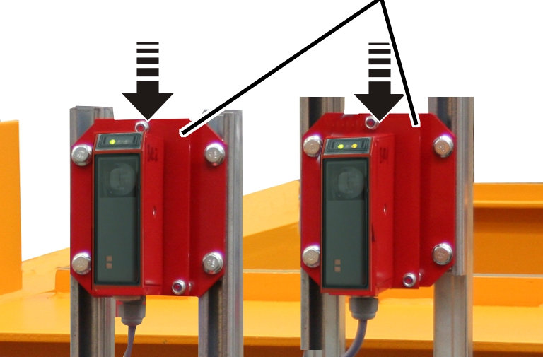
- Push light barriers into the mounts.
- Screw the light barriers until hand-tight.
- Route the light barrier connection cables to the crane panel and secure with cable clips.
Only with light barriers on the end carriage
Light barriersMount for the light barriers
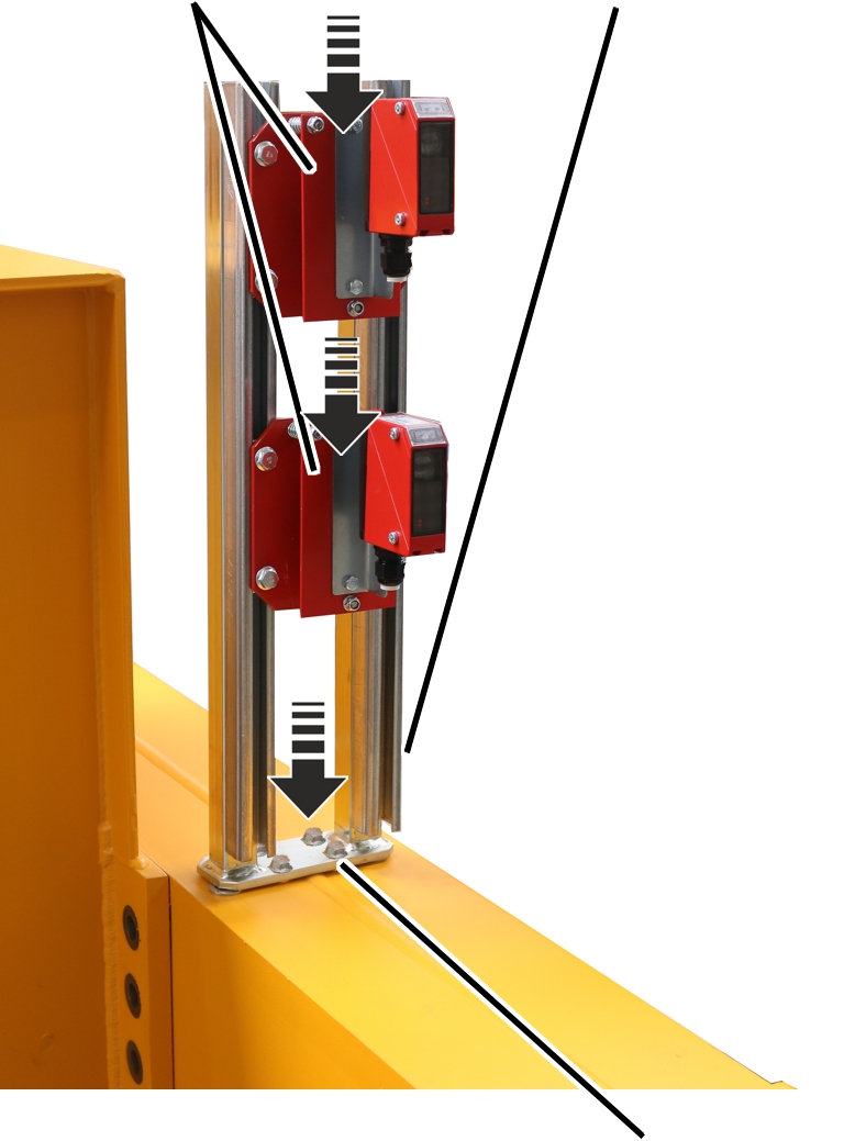
- Place the mount for the light barriers on the holes on the end carriage.
- Screw in the mount for the light barriers with the M8x20 rib screws.
- Push light barriers into the mounts.
- Screw the light barriers until hand-tight.
- Route the light barrier connection cables to the crane panel and secure with cable clips.
Aligning light barriers
Green LED: operating voltageYellow LED (only on the receiver): visual contact to the transmitter exists
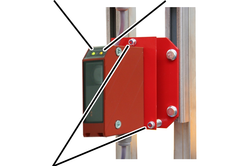
- Align both light barriers on the crane and the other crane on the same run exactly to one another with the self-locking nuts. The yellow LED must light up on the receiver.
- Green LED (on transmitter and receiver): operating voltage present.
- Yellow LED (only on the receiver): visual contact to the transmitter exists.
- As soon as the crane can be traversed: Run the entire crane track in various distances with the crane and the other crane on the same run and check whether the alignment of the light barriers are correct (the yellow LED on the receiver (visual contact exists) must light up in the entire traversing range). If necessary, realign the light barriers.
Due to deviations in the position of the crane track, the alignment of the light barriers can differ from each other.
Mounting the magnetic base antenna for the radio data transmission module
In tandem operation, the ABUControl controls of both cranes are wirelessly connected together and mutually transmit the normal operating modes via a radio data transmission module.
The magnetic base antennas of the radio data transmission modules must be positioned on the trolleys depending on the on-site conditions.
On cranes with tandem control:
The magnetic base antennas of the radio data transmission modules are connected, the connection cables laid and guided out of the panel or prepared for this.
Trolley frameMagnetic base antenna
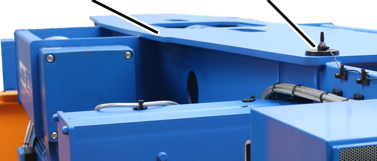
- Mount the magnetic base antennas on the two trolleys in such a way that there is visual contact between them.
- Depending on the type of crane and trolley, the height of the main girder and the on-site conditions, the magnetic base antenna can, for example, be mounted on the trolley frame or on the end carriage on the other side of the trolley frame so that it points toward the partner crane. The connection cable of the magnetic base antenna is long enough for this and can be guided through the existing installation channels.
- If necessary, guide the connection cable of the magnetic base antenna out of the panel. See "Guiding the connection cables into the cable entry housing".
- Attach the magnetic base antenna so that nothing becomes caught during crane travel or trolley travel.
Installing and connecting the inclinometer
With the hook guidance/hook centring function (optional), the deflection of the wire rope is measured using an inclinometer.
To do this, first the inclinometer must be fitted then a calibration run must be carried out to save the wire rope's zero position. See "Calibrating the inclinometer". The orientation of the inclinometer must then be stated in KranOS.
For this work step, access from a laptop or tablet computer to KranOS is necessary. The user "Service" (user level [2]) must be logged in.
Preparing the wire rope angle follower
Only with inclinometer for wire rope hoist D with reeving 4/2 or 8/2 and for wire rope hoist Z
On a type D wire rope hoist with a 4/2 or 8/2 reeving, or on a type Z wire rope hoist, a multi-part wire rope angle follower is fitted, which is secured around the wire rope. The inclinometer, which measures the wire rope's angle of inclination, is mounted on the wire rope angle follower. The rope can pass through the wire rope angle follower. In order to secure the wire rope angle follower around the wire rope, it must first be dismantled so that the two halves can be assembled around the wire rope.
If the cable hoist is being removed from the crane, installed, transported by crane or forklift, or mounted on a lorry, the wire rope angle follower must be removed to prevent it from being damaged.
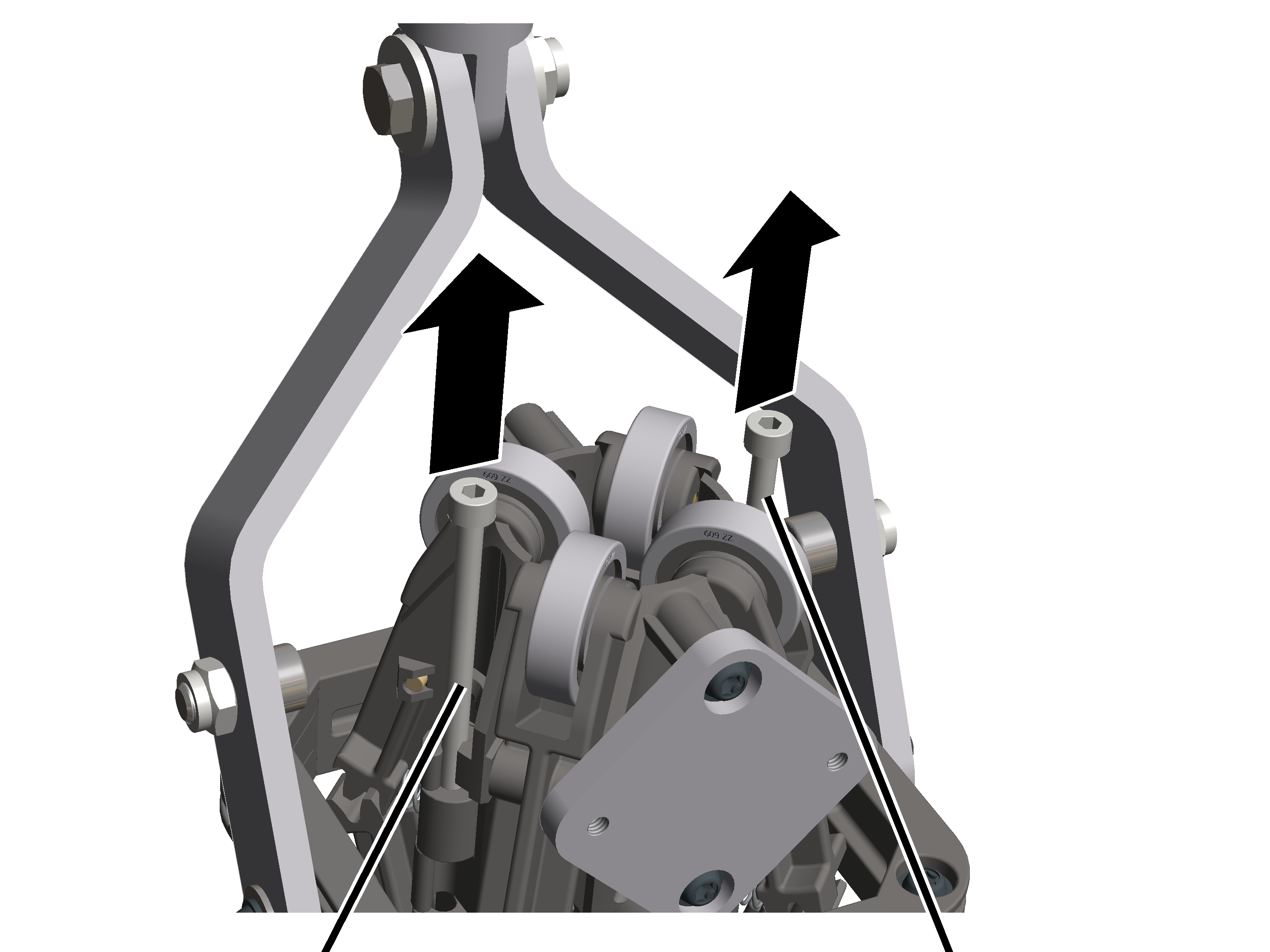
- Remove the cylindrical pins (2x)
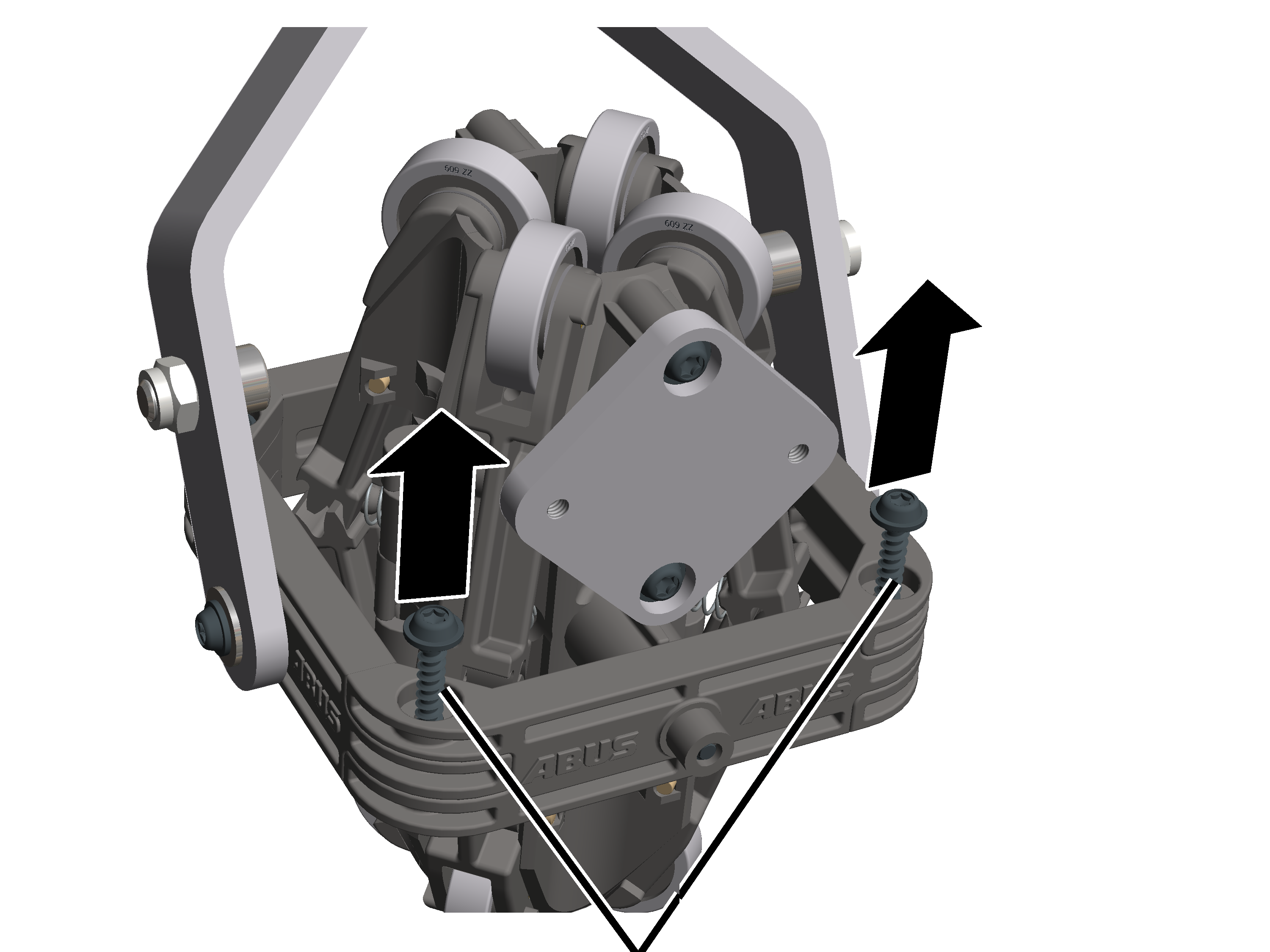
- Undo the rounded head screws K4x17 (2x).
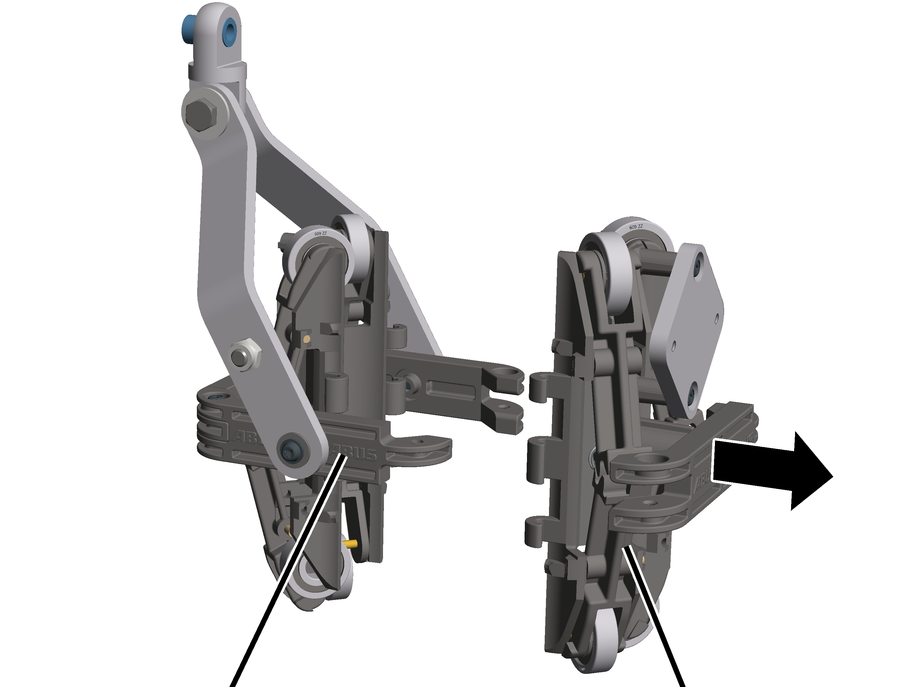
- Pull the semi-circular brackets on the wire rope angle follower apart.
Installing the inclinometer
Only with for wire rope hoist with fixed point crosshead
In wire rope hoists with a fixed point crosshead, the inclinometer is secured to the cable pocket using a clamping device.
PlateRope socket
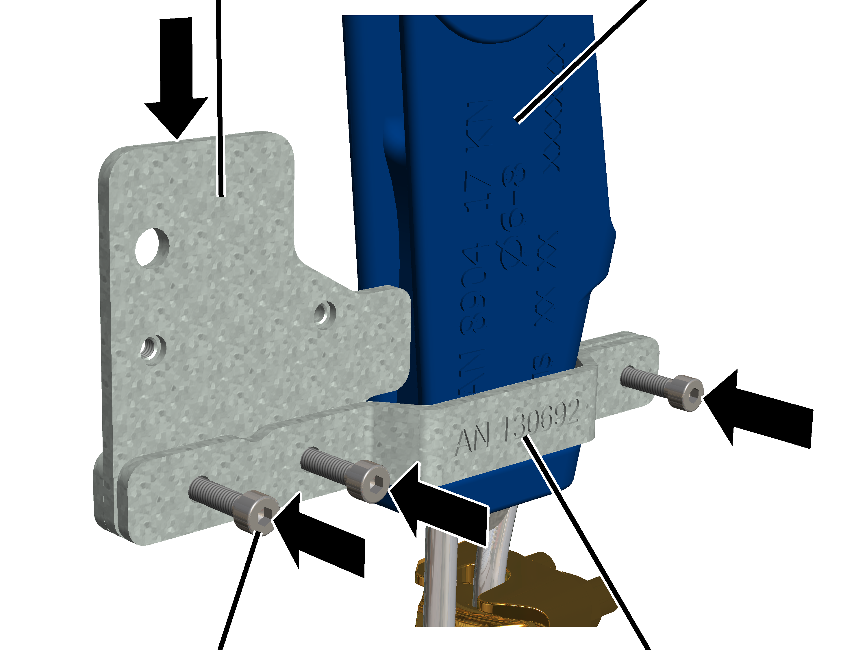
- Clamp the bracket, plate and counter-bracket to the wire rope pocket using M4x16 fillister-head screws (3x).
- Screw the M4x16 fillister-head screws (3) into the press-fit nuts on the counter-bracket. 5 Nm.
Press-fit nutInclinometer
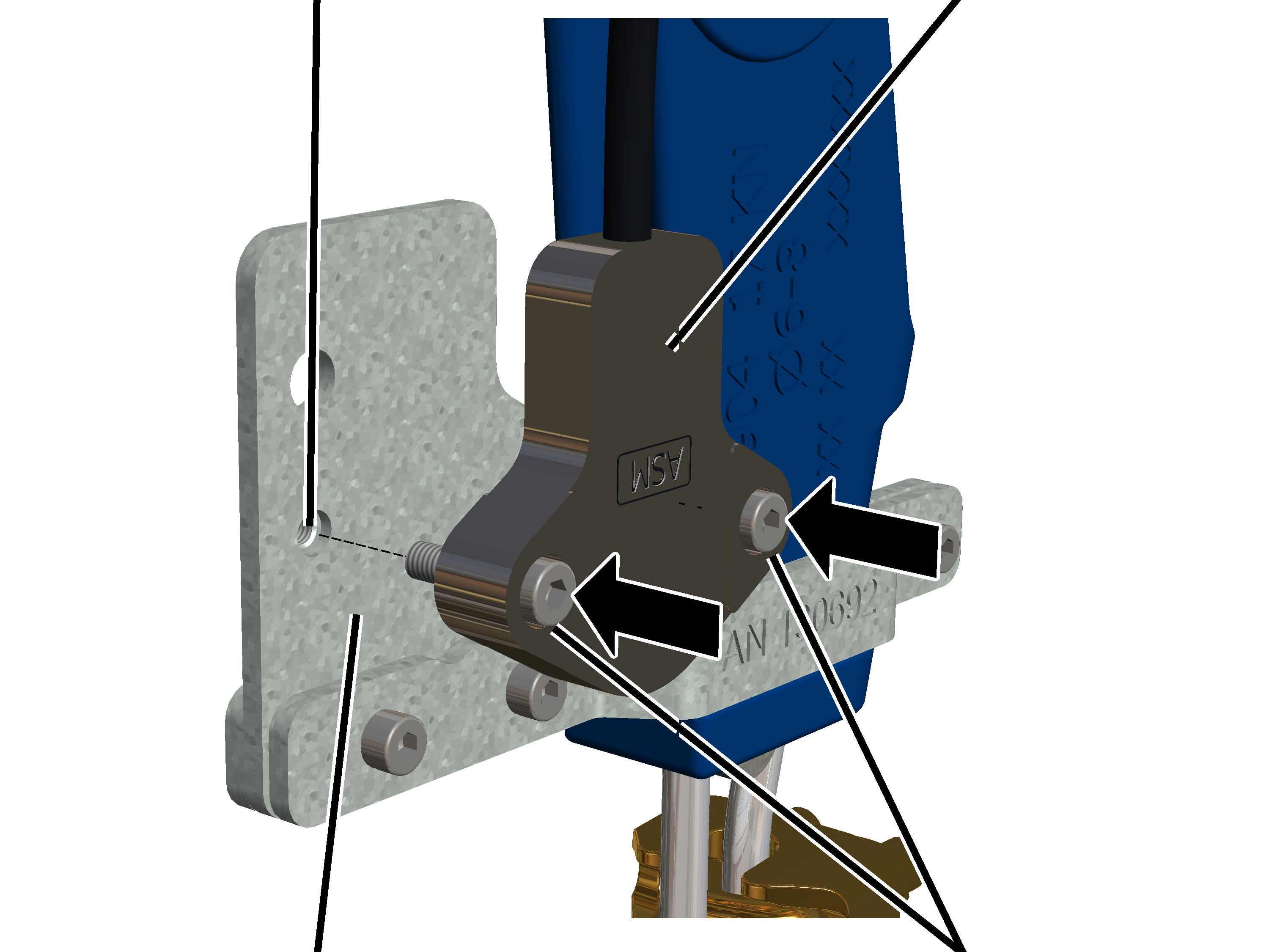
- Screw the inclinometer to the plate using fillister-head screws M4x16 (2x). 5 Nm.
On the back of the plate there are press-fit nuts into which the fillister-head screws are screwed.
Only with wire rope hoist D with reeving 4/2 or 8/2 and form GM 5000
On the D GM 5000 wire rope hoist with a 4/2 or 8/2 reeving, the weld-on plate is welded from the inside to the side wall of the bracket for the deflection roller crosshead, to which the wire rope angle follower is attached.
Rib screw M6x12Weld-on plate
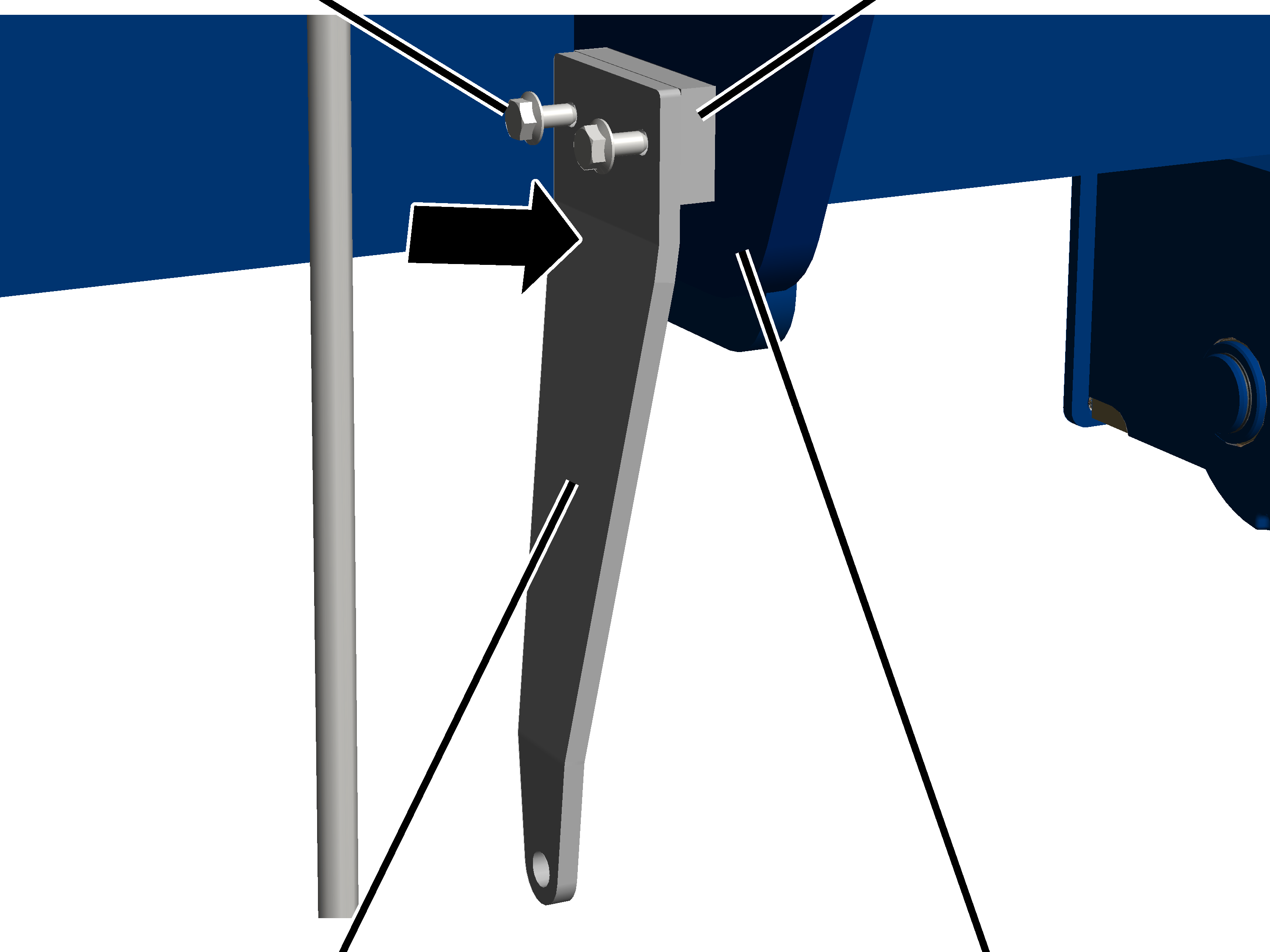
- Screw the bracket to the weld-on plate on the inside of the side panel using M6x12 rib screws (2x). 19 Nm.
Hexagon head screw M6x25Bracket
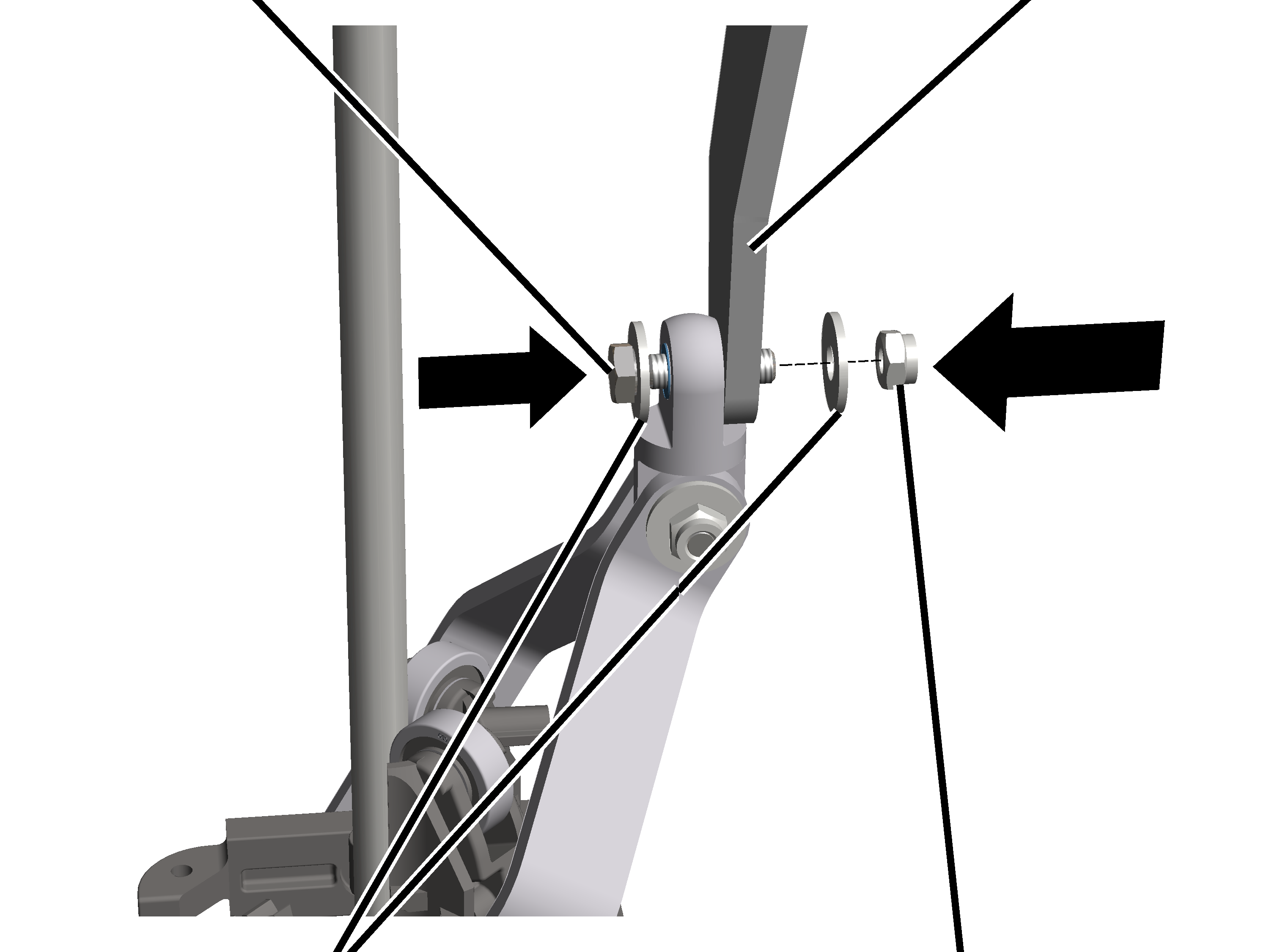
- Insert the M6x25 hexagon head screw with washer through the cross-suspension on the support arm and through the bracket.
- Slide the M6 nut with the washer onto the M6x25 hexagon head screw and tighten it. 10 Nm.
Semi-circular brackets with support arm
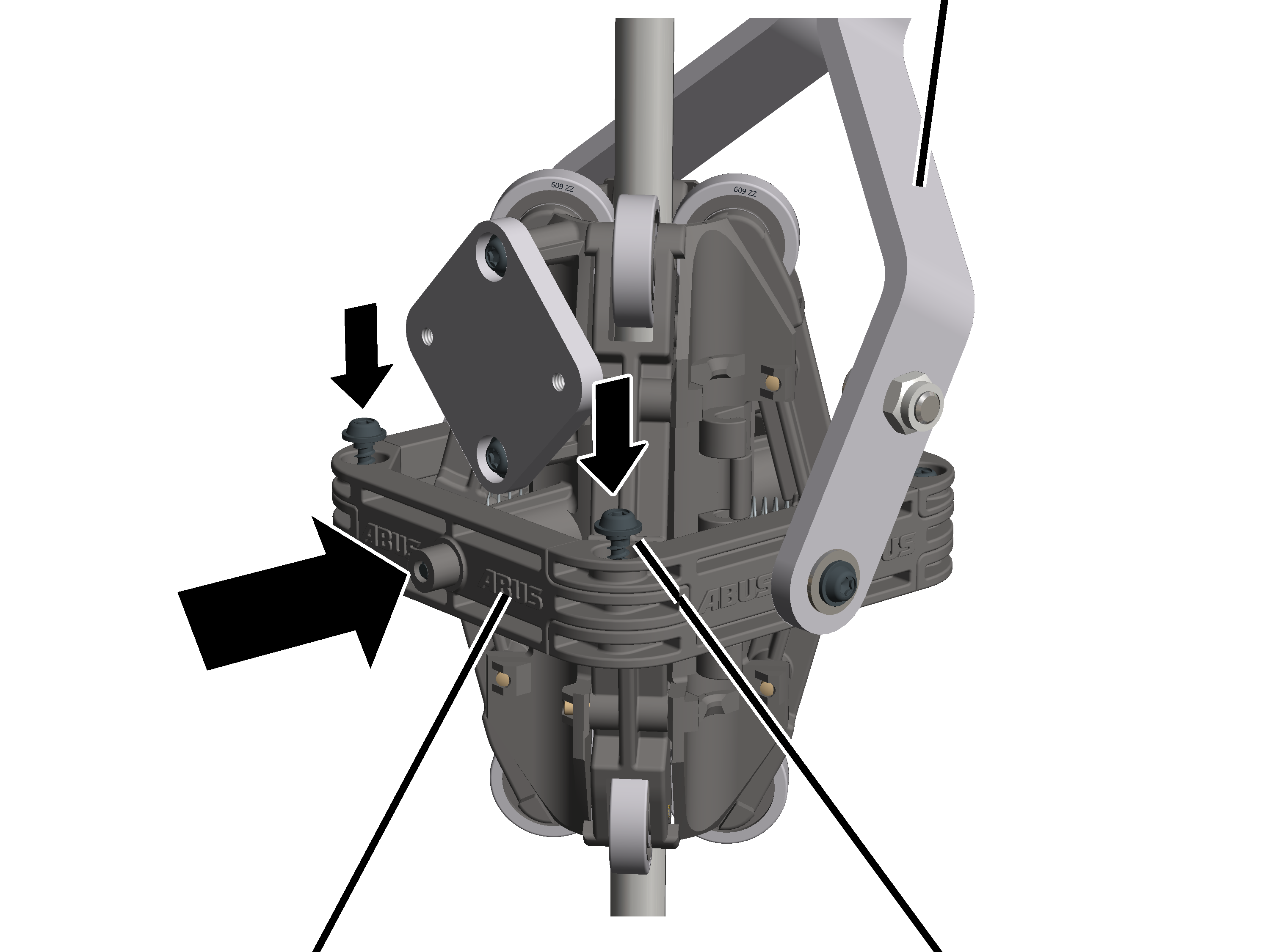
- Screw the previously removed semi-circular bracket to the installed semi-circular bracket with support arm using K4x17 rounded head screws (2x). 1 Nm.
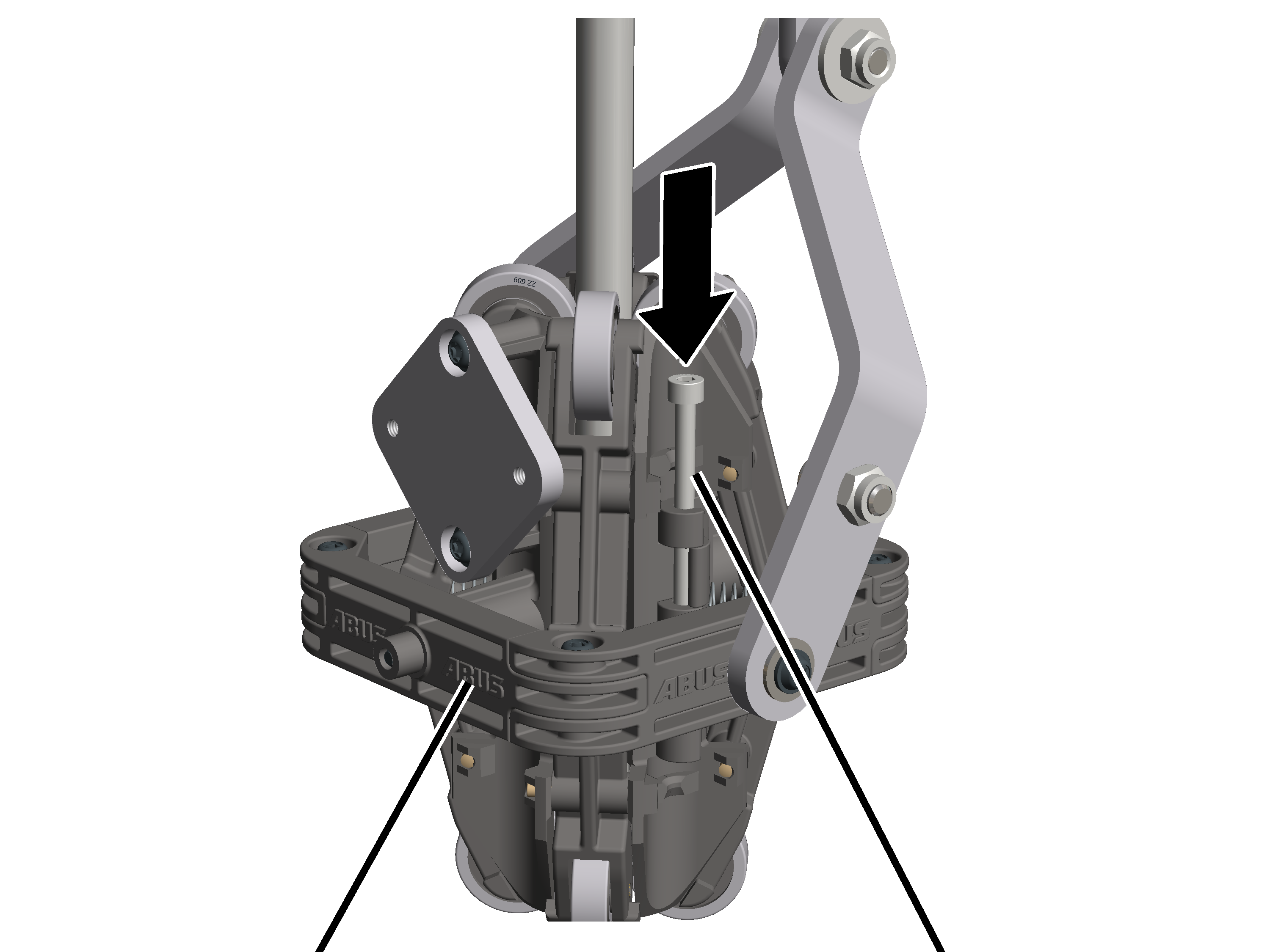
- Push the cylindrical pins (2x) all the way into the semi-circular brackets using the locking mechanism.
InclinometerPlate
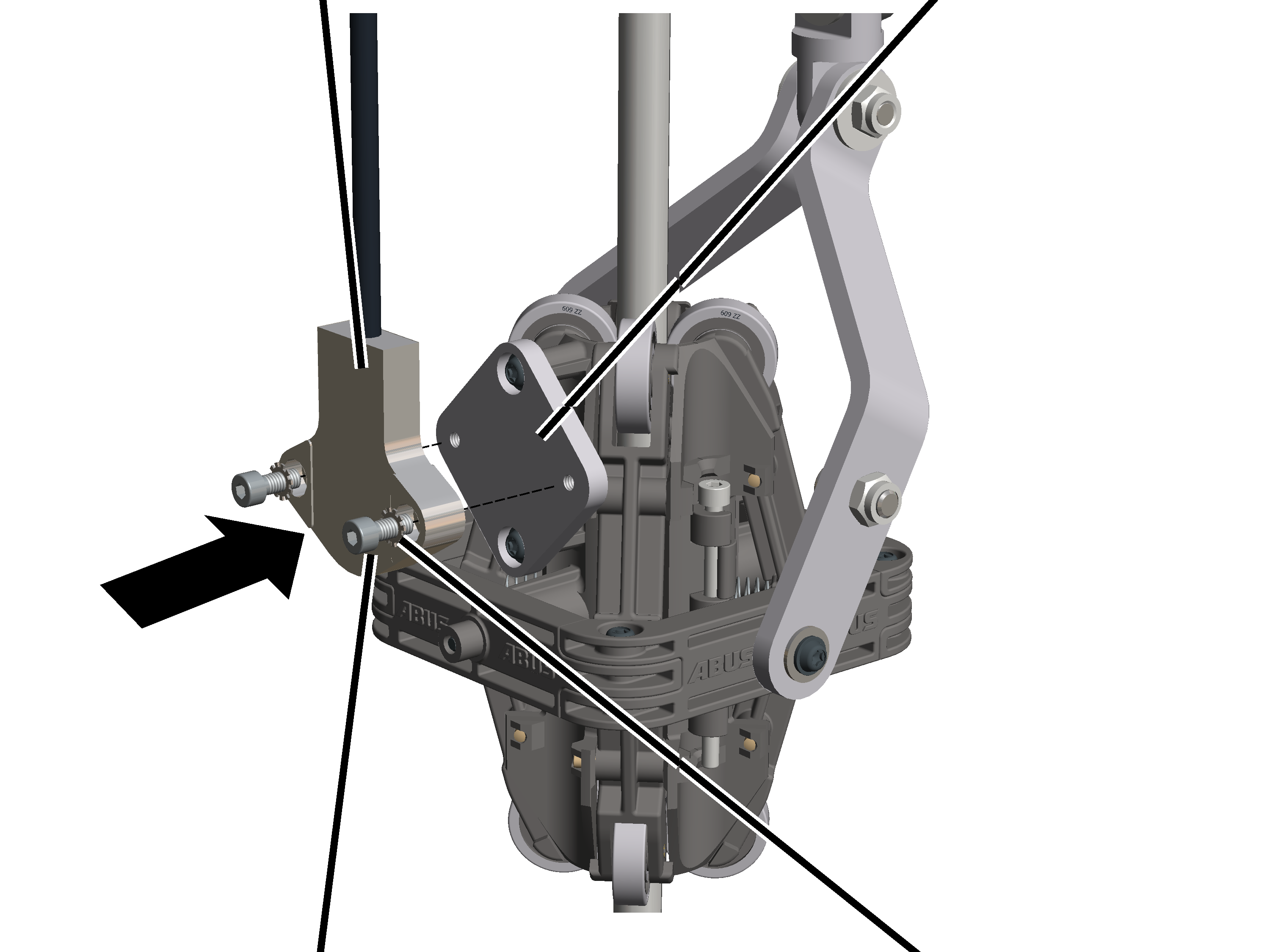
- Secure the inclinometer to the wire rope angle follower plate using M4x12 hexagon head screws (2) and locking washers (2). 3 Nm.
Only with wire rope hoist D with reeving 4/2 or 8/2 and form GM 7000
On the D GM 7000 type wire rope hoist with a 4/2 or 8/2 reeving, the weld-on plate is welded from the outside to the side wall of the bracket for the deflection roller crosshead, to which the wire rope angle follower is attached.
Rib screws M6x12Weld-on plate
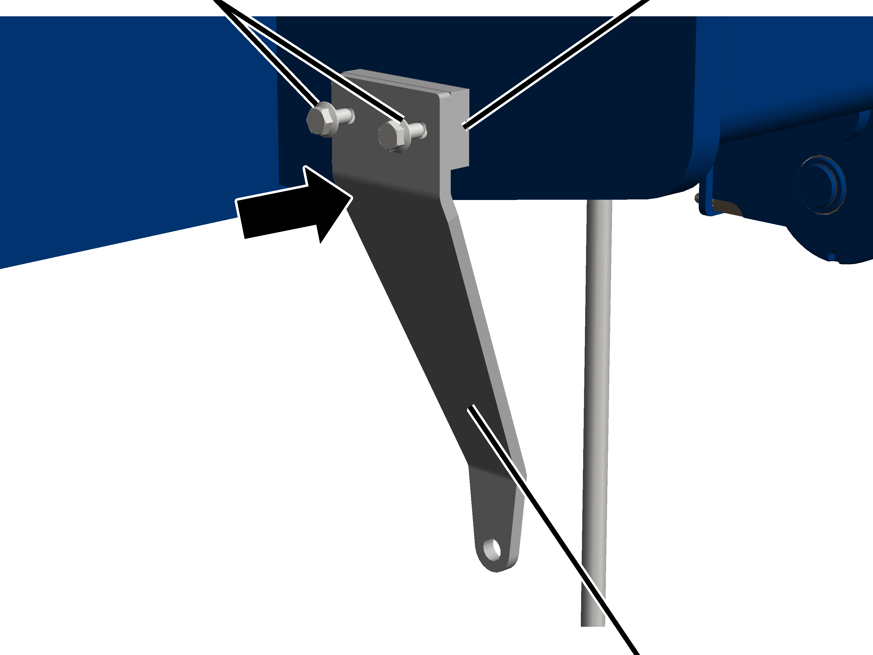
- Screw the bracket to the weld-on plate on the outside of the side panel using M6x12 rib screws (2x). 19 Nm.
Hexagon head screw M6x25Bracket
- Insert the M6x25 hexagon head screw with washer through the cross-suspension on the support arm and through the bracket.
- Slide the M6 nut with the washer onto the M6x25 hexagon head screw and tighten it. 10 Nm.
Semi-circular brackets with support arm
- Secure the semi-circular bracket to the semi-circular bracket with the support arm using K4x17 rounded head screws (2x). 1 Nm.
- Push the cylindrical pins (2x) all the way into the semi-circular brackets using the locking mechanism.
InclinometerPlate
- Secure the inclinometer to the wire rope angle follower plate using M4x12 hexagon head screws (2) and locking washers (2). 10 Nm.
Only with wire rope hoist Z
On the type Z wire rope hoist, a weld-on plate is attached to the underside of the trolley frame, to which the wire rope angle follower is secured.
Weld-on plate
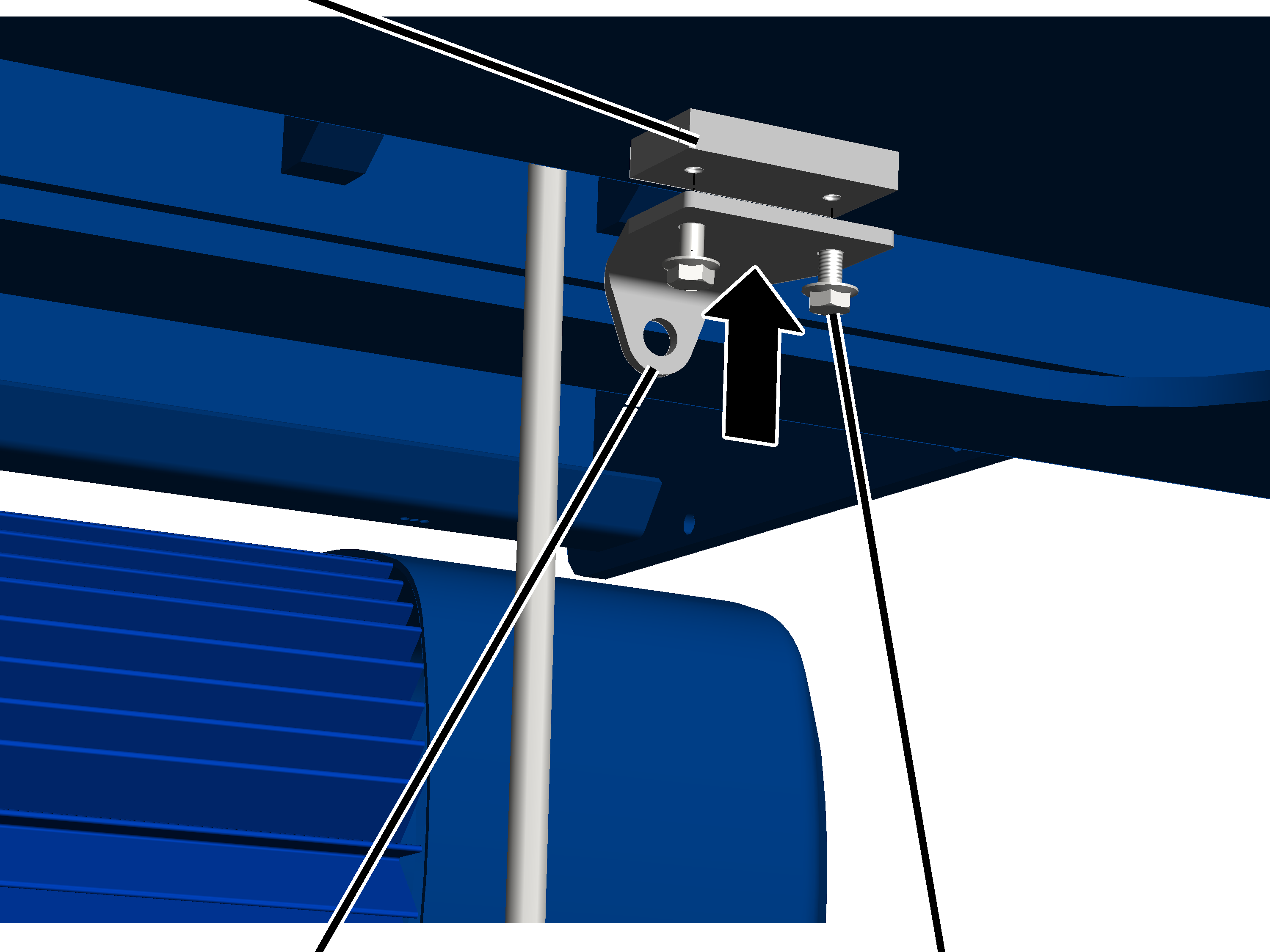
- Secure the bracket to the weld-on plate using M6x12 rib screws (2x). 19 Nm.
Hexagon head screw M6x25Washer
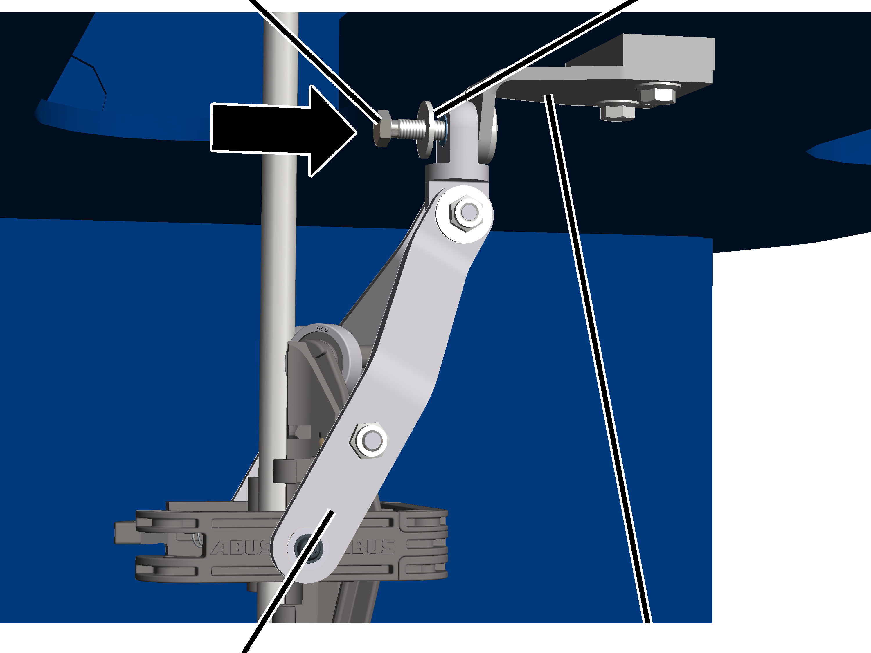
- Insert the M6x25 hexagon head screw with washer through the cross-suspension on the support arm and through the bracket.
Washer
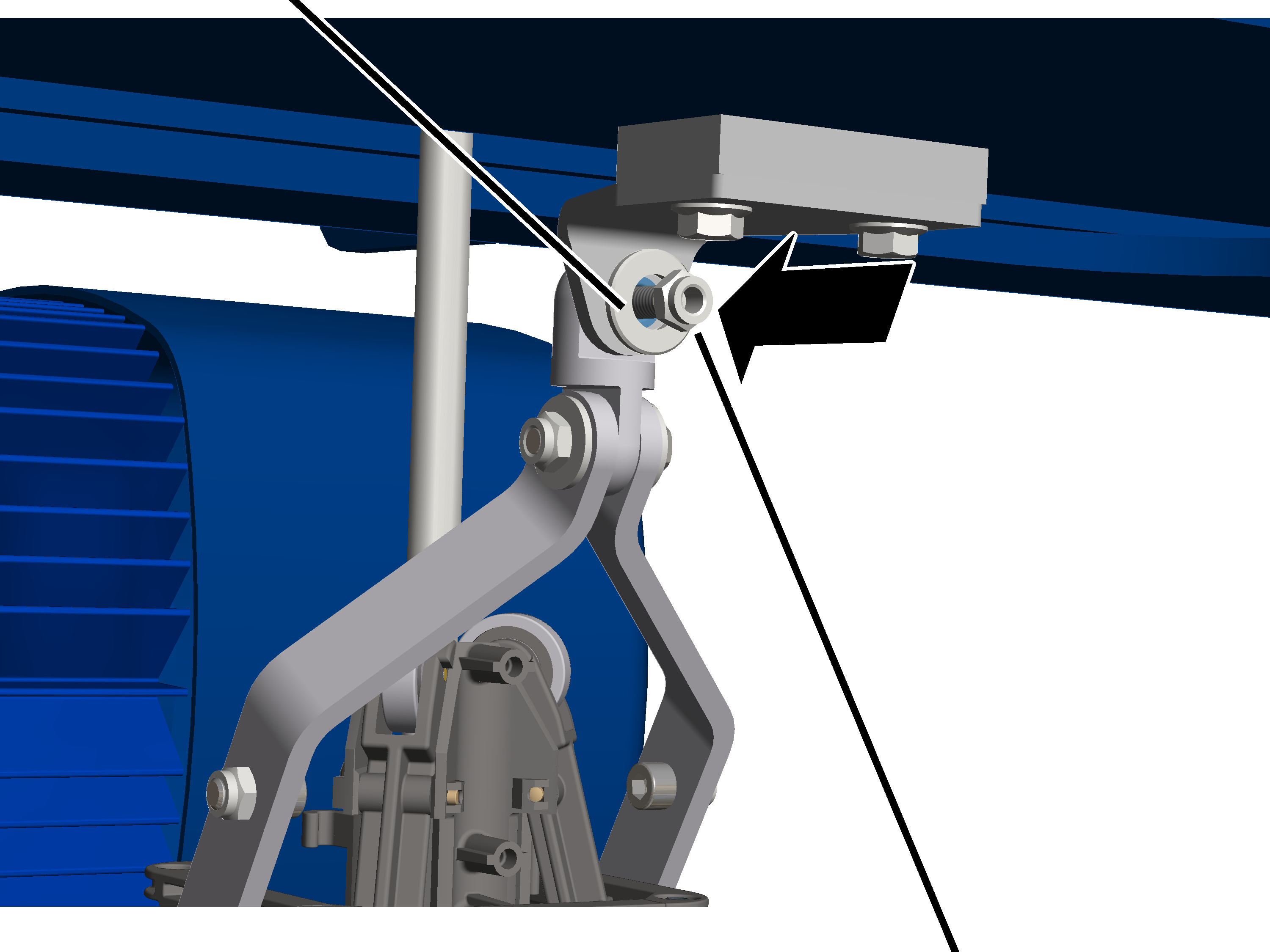
- Slide the M6 nut with the washer onto the M6x25 hexagon head screw and tighten it. 10 Nm.
Semi-circular brackets
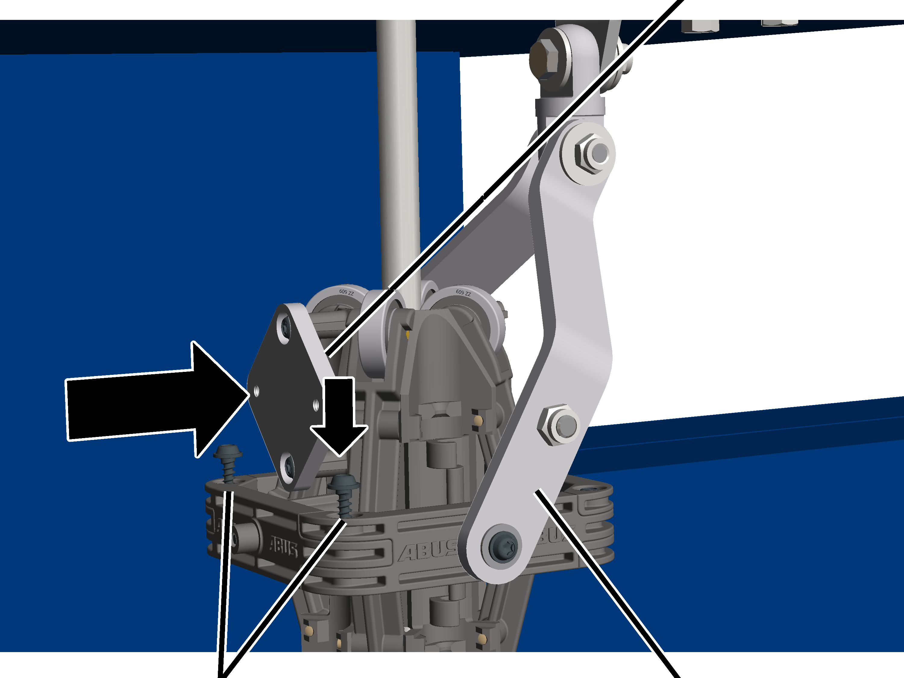
- Secure the semi-circular bracket to the semi-circular bracket with the support arm using K4x17 rounded head screws. 1 Nm.
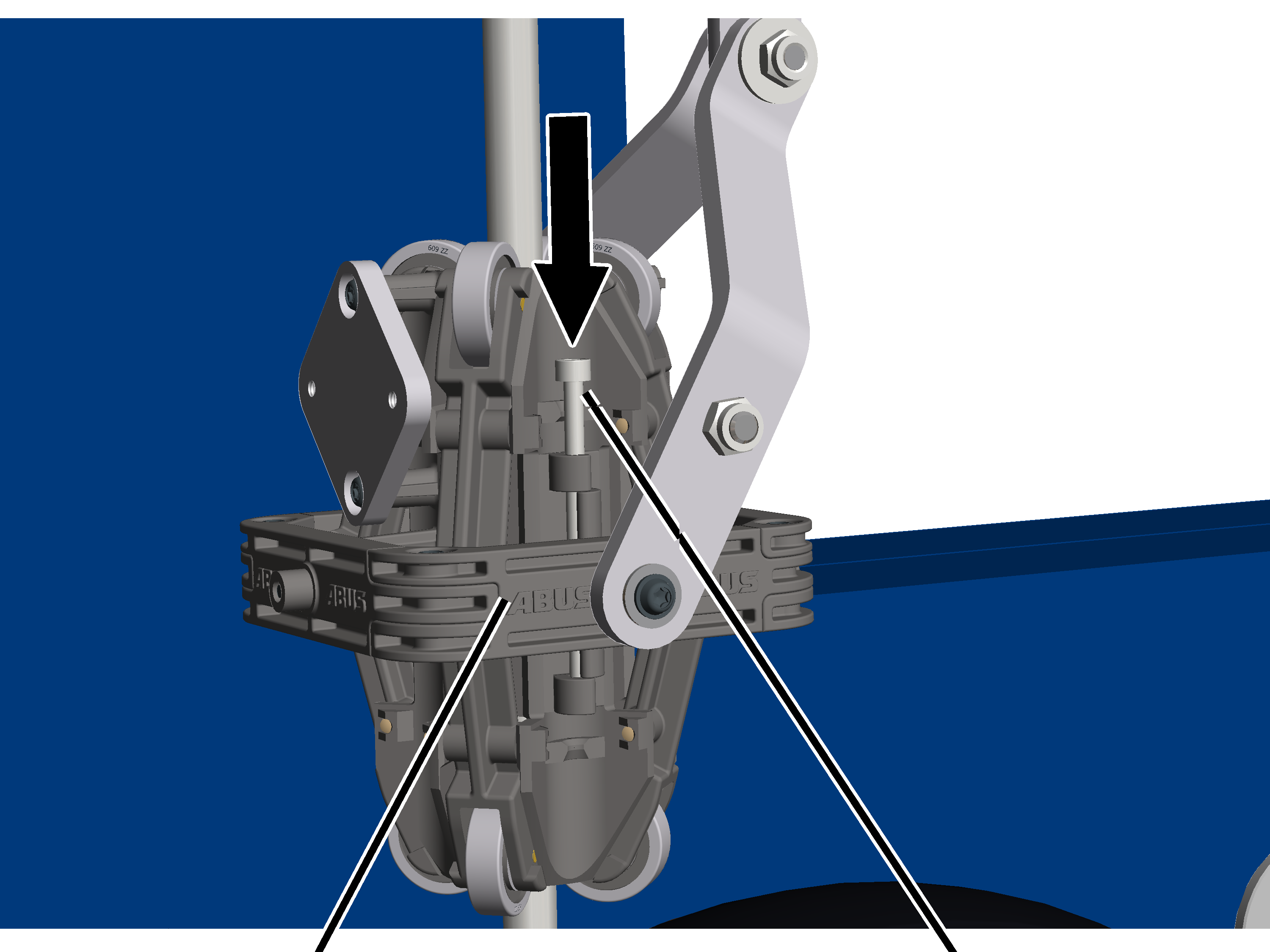
- Push the cylindrical pins (2x) all the way into the semi-circular brackets using the locking mechanism.
Inner hexagon head screw M4x12Locking washer
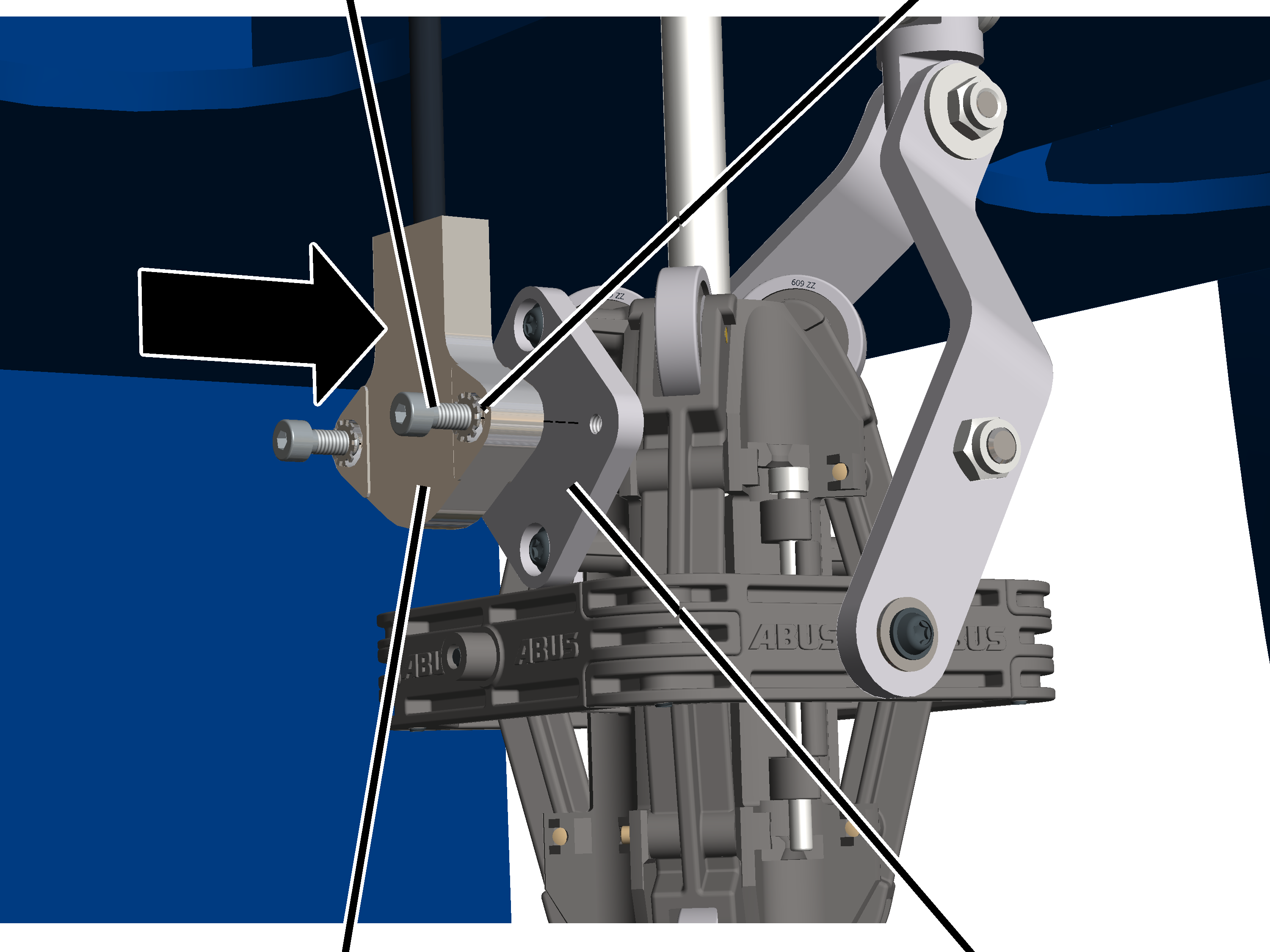
- Secure the inclinometer to the wire rope angle follower plate using M4x12 hexagon head screws (2) and locking washers (2). 3 Nm.
Connecting the inclinometer
- Route the wire rope angle sensor connector to the absolute encoder and plug it in.
Calibrating the inclinometer
To use the hook guidance and hook centring, the inclinometer must be calibrated. To do this, a calibration run must be carried out to save the wire rope's zero position. The hook guidance and hook centring are only available once calibration has been successfully completed.
Notes:
- Before the inclinometer can be calibrated, the absolute rotary encoder must be referenced. See "Referencing the absolute rotary encoder".
- To ensure accurate calibration, the load hook must hang vertically throughout the calibration run. The best way to achieve this is to attach a load to the load hook. In the case of small load hooks and those fitted with a spring-loaded cable drum, a load must always be attached during the calibration run to ensure that the load hook hangs vertically.
- The inclinometer must be recalibrated after every dismantling (e.g. when changing the wire rope) or when replacing the inclinometer.
For this work step, access from a laptop or tablet computer to KranOS is necessary. The user "Service" (user level [2]) must be logged in.
Overview: Navigation in KranOS |
|---|
User "SERVICE" 🡪 "Hoist" 🡪 "Hoist profile parameter" 🡪 "Maximum Inclinometer parameter" |
- Log in to KranOS with user "Service" (user level [2]). See "Logging into and registering in KranOS".
- Select the desired hoist (e.g. hoist 1) in the main menu.
- The window for the requested hoist appears.
- Click on the "Hoist profile parameter" menu item in the "Settings" menu (three horizontal bars).
- The "Hoist profile parameter" window appears.
- Click on the "Inclinometer parameter" menu item in the "Settings" menu (three horizontal bars).
- The "Inclinometer parameter" window appears.
"Calibrating inclinometer" button
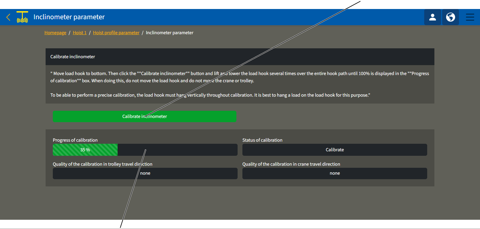
- Lower the load hook all the way down.
- If possible and applicable: attach the load.
- Click the "Calibrating inclinometer" button.
- Raise and lower the load hook along its full travel until 100% is displayed in the "Calibration progress" field.
During the calibration run, the trolley and the crane must not be moved, as this would cause the load hook to swing. This would compromise the calibration. Do not move the load hook in any other way during the calibration run either.
The fields "Calibration quality in the trolley travel direction" and "Calibration quality in the crane travel direction" show how good the result of the calibration run is.
- Check the correct setting of the inclinometer. See "Setting the inclinometer position".
Setting the inclinometer position
To ensure that the hook assistants can measure the rope deflection correctly, the alignment of the rope angle sensor must be set correctly in KranOS.
Before the alignment of the inclinometer can be set, the inclinometer must be calibrated. See "Calibrating the inclinometer"..
For this work step, access from a laptop or tablet computer to KranOS is necessary. The user "Service" (user level [2]) must be logged in.
Overview: Navigation in KranOS |
|---|
User "SERVICE" 🡪 "Movement profile" |
- Log in to KranOS with user "Service" (user level [2]). See "Logging into and registering in KranOS".
- Click on the "Movement profile" menu item in the "Settings" menu (three horizontal bars).
- The "Movement profile" window appears.
"Inclinometer rotated by 90°" buttonInclinometer orientation drop-down menu
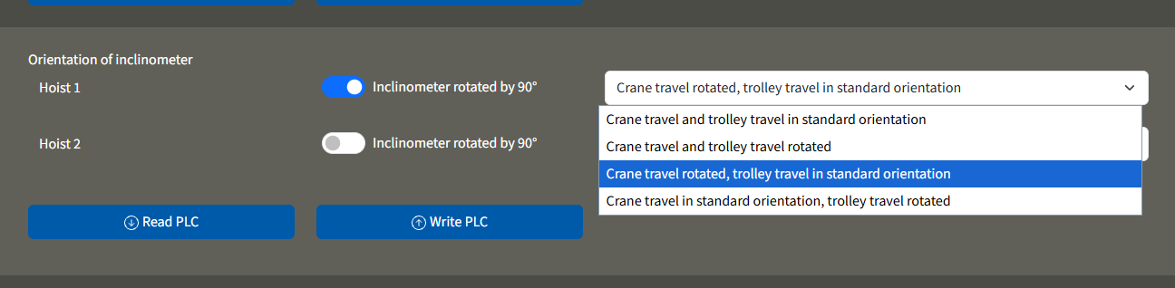
- Use the drop-down menu to select the orientation of the rope angle sensor for the relevant hoist.
- If necessary, use the 'Inclinometer rotated by 90°' switch to select the installation orientation of the inclinometer.
- The button's background turns blue.
- Click on the "Write PLC" button.
Inspection
This section applies to anyone who inspects and accepts the crane in accordance with occupational health and safety requirements
The crane must be regularly inspected in order to guarantee safe operation. The end user is responsible for this regular inspection.
Read before starting work
Test intervals
The regular inspection is performed at least once annually.
Under certain conditions, more frequent regular inspections may be necessary. Reasons include:
- Frequent operation at the load capacity
- Working in multiple shifts
- Frequent use
- Dusty or chemically aggressive environment
The end user is responsible for checking the requirements and determining the test intervals. ABUS will gladly assist you if questions arise.
Requirements for the examiner
The end user of the crane is responsible for the proper qualifications of the examiner.
Examples of qualified persons:
- Persons with comprehensive knowledge from specialist training in engineering and in the electrical systems of cranes.
- Persons with sufficient experience in the operation, installation and maintenance of cranes.
- Persons with comprehensive knowledge regarding the relevant technical rules, directives and safety regulations applicable in the respective country.
- Persons receiving regular training from ABUS.
Scope of the test
The qualified person inspecting the crane is responsible for the type and scope of the test.
Overview: testing crane with ABUControl
In addition to the points described here, all points outlined in the other supplied product manuals must also be checked.
The decision as to whether the crane is in perfect condition may be made only by the person inspecting the crane. Any inadequacies, if found, must be eliminated. The examiner decides whether the crane has to be tested again afterward.
If locally applicable regulations specify further tests, these are likewise to be carried out.
Additionally, at least the following points must be inspected:
- Read out the operating data and the load population recorder for further calculation of the remaining service life. See "Reading operating data and load population recorder".
- During normal operative travel of the top hoist limiter: test backup limiter. See "Testing backup limiter".
- Inspect the wire rope with the aid of the discard prognosis. See "Inspecting wire rope with the aid of the discard prognosis" and "Displaying parameters for maximum acceptable wear and data of the rope drive".
- Check the overload protection. See "Check the overload protection".
Reading operating data and load population recorder
ABUControl determines numerous operating data in ongoing operation and displays an overview of these. The operating data, especially the operating hours counter and load population recorder, are important for regular inspection.
For this work step, access from a laptop or tablet computer to KranOS is necessary. The user "CUSTOMER" (user level ‚[1]) or "SERVICE" (user level [2]) can be logged in. However, access is also possible without login (user level [0]).
Opening operating data
Without login:
- Establish WLAN connection.
- Open KranOS in the browser. See "Logging into and registering in KranOS".
- The "Operating data" window appears.
For the logged in user:
- In the start window: Click on the "Operating data" menu item in the "Settings" menu (three horizontal bars).
- The window with the operating data appears.
Note:
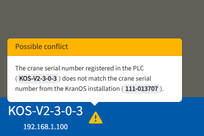
If the crane serial number stored in the PLC does not match the crane serial number in KranOS, a message will appear indicating the conflict.
Reading operating data
"Operating hours" field"Reversing motions" field
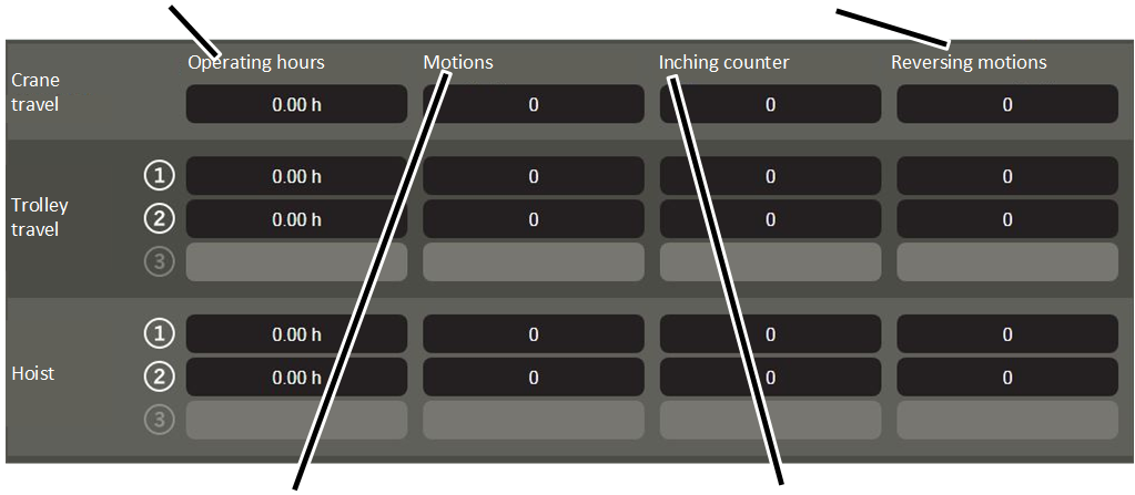
- Read the corresponding value from the line for the desired crane axis.
- "Operating hours": time that the drive or drives of the respective crane axis were in motion.
- "Motions": Number of motions of the respective crane axis. In each case, a motion is counted if the corresponding drive accelerates from a standstill.
- "Inching counter": Number of short motions. The number is increased by one when the corresponding drive accelerates from a standstill and runs only for up to 2 seconds. At the same time, the "Motions" description field increases by one.
- "Reversing motions": Number of reverse motions. The number is increased by one when the corresponding drive accelerates from a given motion direction directly into the opposite direction within 2 seconds. At the same time, the "Motions" description field increases by one.
Reading the load population recorder
"Consumed value" field"Overload counter" field
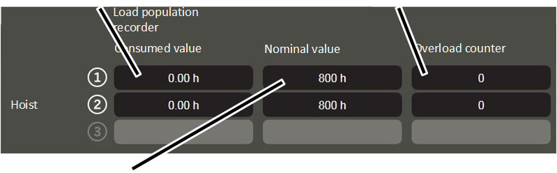
- "Consumed value": calculated full-load hours of the hoist.
- "Nominal value": maximum permitted full-load hours of the hoist.
- "Overload counter": Number of lifting motions with overload. The number always increases by 1 if the hoist lifts a load that is over the maximum load capacity of the crane. At the same time, the "Motions" description field also increases by 1.
For further information about the evaluation of the remaining service life: See "General product manual for ABUS cranes".
Notes:
- The displayed values are updated as the "Operating data" window is displayed. Thus you can observe in which operating situation the displayed values are increased.
- The values are saved in ABUControl. If the PLC is replaced, the values must be manually transferred.
Testing backup limiter
Only with normal operative travel to the top hoist limiter
This section only applies if the top hoist limiter may be travelled to during normal operation.
The top hoist limiter may be intentionally triggered during the normal course of work. The top hoist limiter must be tested upon switching on the crane.
If the top hoist limiter is damaged through normal use, an additional backup limiter handles the shutdown. This backup limiter must be checked within the course of regular inspection.
Moving the load hook to the correct position
- Move the load hook out of the limit switch range (up or down).
The load hook may not be within the limit switch range prior to the test.
Testing backup limiter
'Top' position
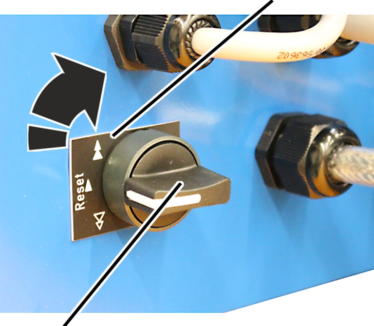
- Turn the toggle switch to the 'top' position and hold.
- Raise the load hook up slowly.
- The load hook moves up.
- Due to the activated toggle switch, the load hook does not stop as usual at the switching point of the top hoist limiter, it moves onwards instead.
- The backup limiter is activated.
- The main contactor switches off.
- The backup limiter has now been checked.
If the main contactor did not switch off:
- There is a problem with the crane circuitry or individual components. The crane may no longer be operated.
- Shut down the crane.
- Contact ABUS Service. See “ABUS Service”.
Switching the crane on again
'Bottom' position
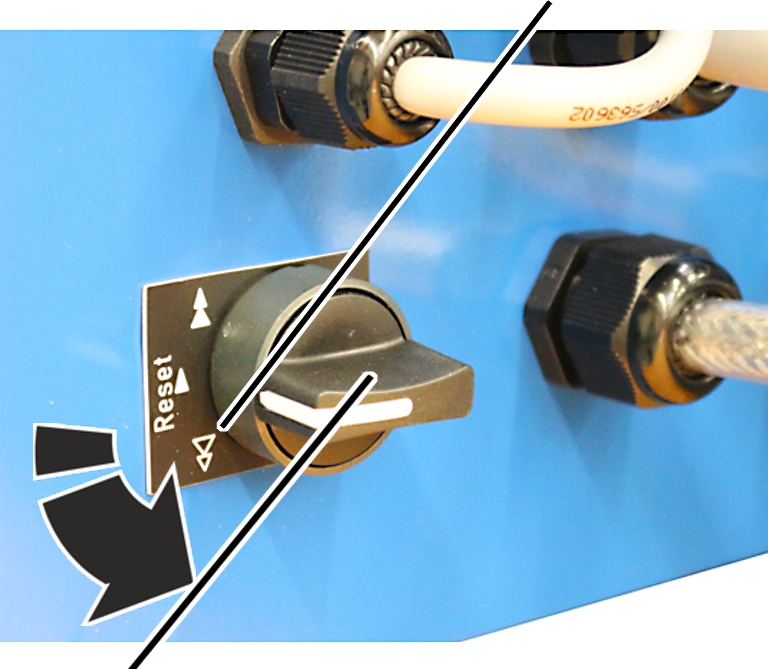
- Turn the toggle switch to the 'bottom' position and hold.
- The main contactor is bridged.
- The crane switches back on.
- Move the load hook out of the limit switch range.
Only with twin hoist
The procedure for the twin hoist does not differ significantly.
- Check the backup limiter on hoist drive 1.
- Restart the crane at hoist drive 1.
- Check the backup limiter on hoist drive 2.
- Restart the crane at hoist drive 2.
Inspecting wire rope with the aid of the discard prognosis
The wire rope test is made easier and more reliable through ABUControl, which displays wire rope sections for which pronounced wear has been calculated.
For this work step, access from a laptop or tablet computer to KranOS is necessary. The user "CUSTOMER" (user level ‚[1]) or "SERVICE" (user level [2]) must be logged in.
Calling up "Maximum acceptable wear"
Overview: Navigation in KranOS |
|---|
User "CUSTOMER" or "SERVICE" 🡪 "Hoist" 🡪 "Maximum acceptable wear" |
- Login to KranOs with user "CUSTOMER" (user lever [1]) or "SERVICE" (user level [2]). See "Logging into and registering in KranOS".
- Select the desired hoist (e.g. Hoist 1) in the main menu.
- The window for the requested hoist appears.
- Click on the "Wear maximum acceptable wear" menu item in the "Settings" menu (three horizontal bars).
Reading the calculations for the maximum acceptable wear
"Rope position" column"Wear length" column
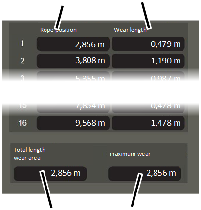
- The window "Maximum acceptable wear" appears.
- The table shows one or more wire rope sections (one wire rope section per line) for which ABUControl has calculated pronounced wear.
- The "Rope position" column indicates where the respective wire rope section is located. The length is measured from the fixed point to the start of the respective wire rope section.
- The "Wear length" column shows the length of the respective wire rope section exhibiting pronounced wear. This is measured from the start of the position given in the "Rope position" column.
- The "Total length wear area" field shows the wire rope section from the table that has been calculated as the wire rope section with highest wear.
- The "Maximum wear" field indicates the degree of wear on the wire rope section with highest wear.
- Start the inspection of the wire rope at the displayed rope positions.
All displayed wire rope sections should be checked in succession. This is where broken wires are expected to appear first.
Inspecting the wire rope
On all displayed wire rope sections with pronounced wear:
Distance from the fixed point up to the start of the wire rope section ("Wire length" field)
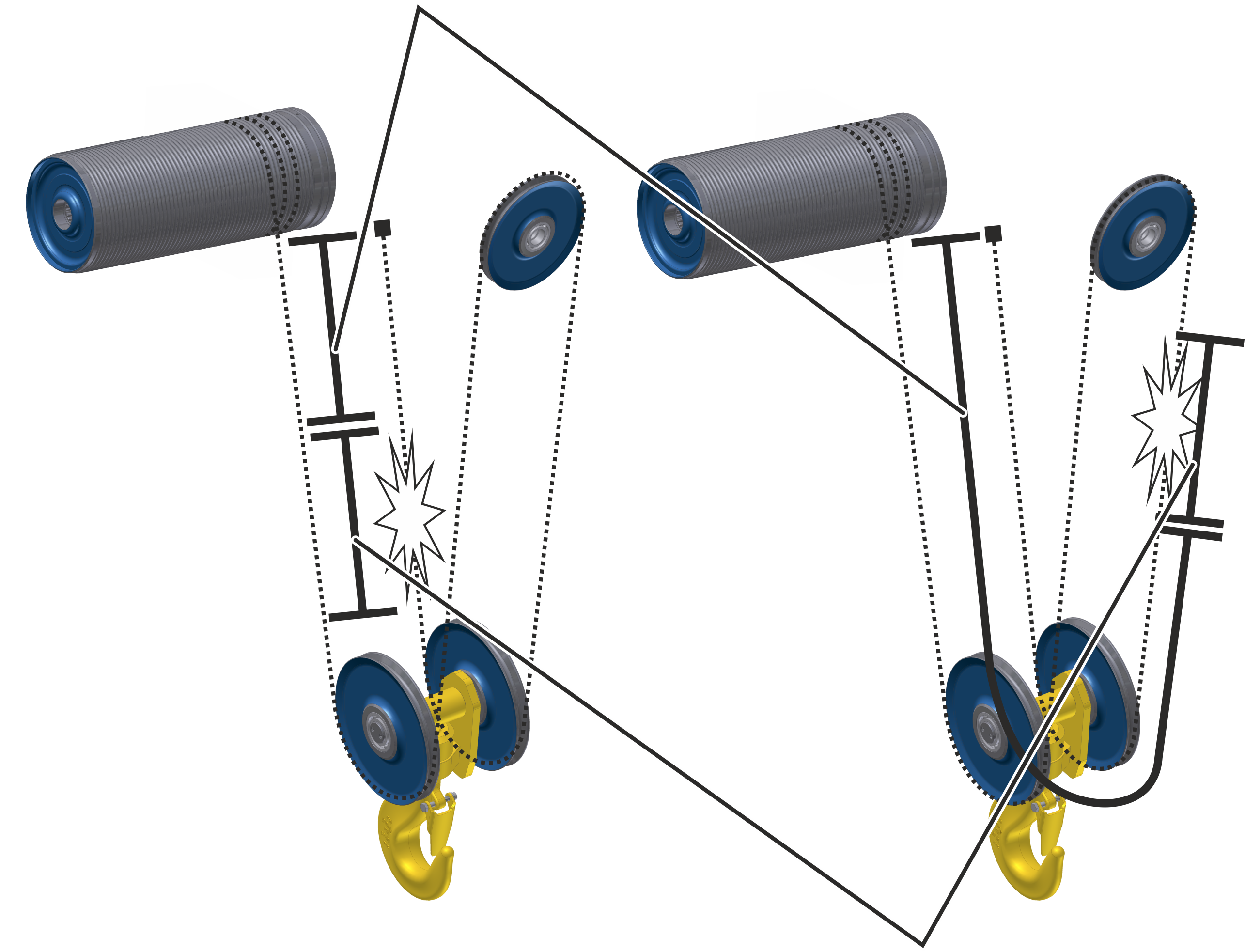
- Lower the load hook as far down as possible.
This facilitates the measuring of the wire rope.
- Measure the distance of the "Rope position" from the fixed point of the wire rope hoist.
This is the point at which the pronounced wear begins on the wire rope section.
The wire rope section with highest wear is usually located in the first fall, but it can also lie in other falls depending on usage of the crane. In this case, measure the distance of the "Rope position" starting from the fixed point of the wire rope hoist and around the reel on the bottom block.
- Measure the "Total length wear area" from the start of the wire rope section.
- This is the area where the wire rope section with the greatest wear is located. This is where broken wires are expected to appear first.
- Start the wire rope test here.
See also "General Product Manual for ABUS Cranes", section "Inspecting the wire rope".
If it is determined that the maximum acceptable wear has not yet been reached at this point:
- Inspect the entire remaining wire rope.
Only with wire rope hoists with a twin hoist or with a true vertical lift hoist
This section applies only to wire rope hoists with a twin hoist (not one but both wire rope ends are each wound onto their own cable drum) and wire rope hoists with a True Vertical Lift hoist (not one but both wire rope ends are wound together onto a shared cable drum).
Checking both halves of the wire rope
Compensating sheave
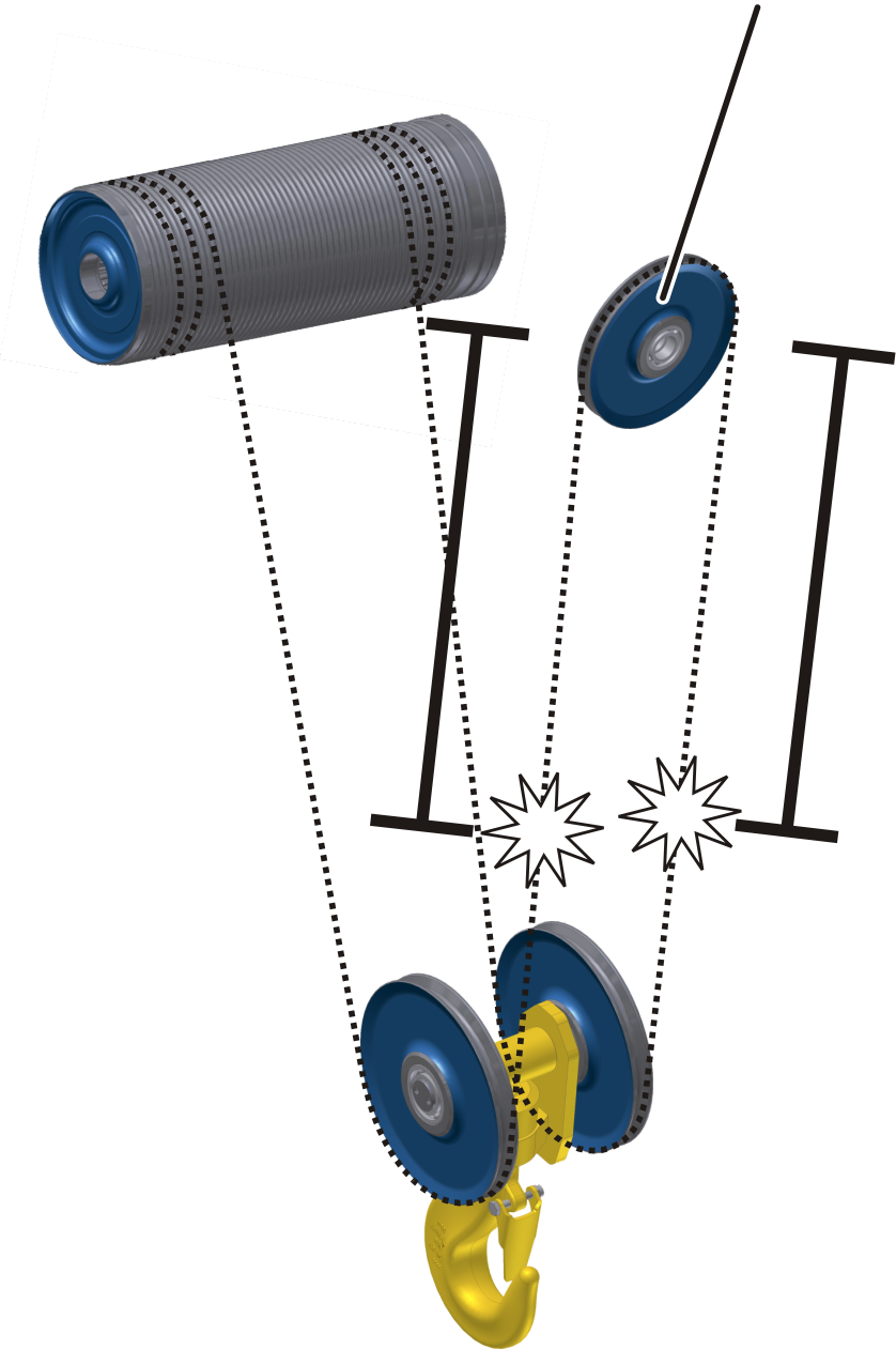
These wire rope hoists wind the wire rope at both ends. The middle wire rope piece remains nearly motionless on the compensating sheave of the wire rope hoist or the bottom block. The compensating sheave functions as a fixed point and the two wire rope halves are considered two individual wire ropes.
The wear calculated by ABUControl applies to the first as well as the second wire rope half. Due to the symmetrical arrangement, the same wear is assumed for both wire rope halves.
- Inspect the wire rope half both to the left of the compensating sheave and to the right of the compensating sheave. The compensating sheave is considered a fixed point.
Checking the wire rope on the compensating sheave
ABUControl considers the wire rope on the compensating sheave as a fixed point.
However, due to swinging of the load and marginal variations in rotation of the two cable drums, wear also occurs on the wire rope on the compensating sheave.
Compensating sheave
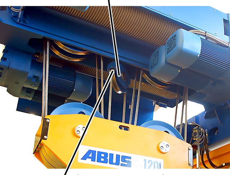
- Inspect the wire rope piece on the compensating sheave (middle deflection roller at top on the the wire rope hoist or on the bottom block) especially carefully in addition to the rest of the wire rope.
Replacing the wire rope
If the wire rope has reached its maximum acceptable wear:
- Replace the wire rope. See "Replacing the wire rope" as well as the product manual of the wire rope hoist.
Displaying parameters for maximum acceptable wear and data of the rope drive
For this work step, access from a laptop or tablet computer to KranOS is necessary. The user "CUSTOMER" (user level ‚[1]) or "SERVICE" (user level [2]) must be logged in.
Calling up "Maximum acceptable wear parameter"
Overview: Navigation in KranOS |
|---|
User "CUSTOMER" or "SERVICE" 🡪 "Hoist" 🡪 "Hoist profile parameter" 🡪 "Maximum acceptable wear parameter" |
- Login to KranOs with user "CUSTOMER" (user lever [1]) or "SERVICE" (user level [2]). See "Logging into and registering in KranOS".
- Select the desired hoist (e.g. Hoist 1) in the main menu.
- The window for the requested hoist appears.
- Click on the "Hoist profile parameter" menu item in the "Settings" menu (three horizontal bars).
- The "Hoist profile parameter" window appears.
- Click on the "Maximum acceptable wear parameter" menu item in the "Settings" menu (three horizontal bars).
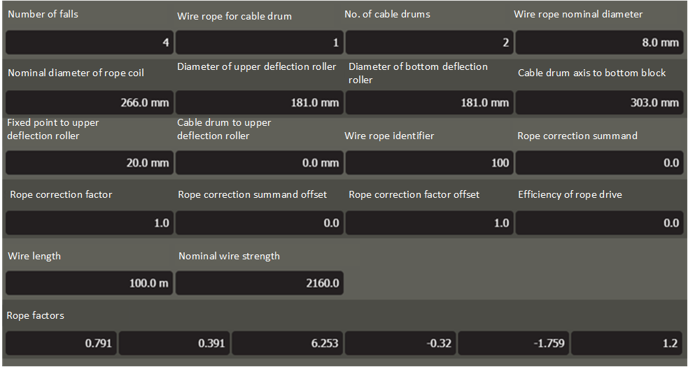
- The window "Maximum acceptable wear parameter" appears.
- Read off the desired parameters:
- "Number of falls": Number of falls of the wire rope running between the bottom block and the trolley frame.
- "Wire rope for cable drum":
1: One rope end is wound onto the cable drum, the other rope end is fastened to the fixed point.
2: Both rope ends are wound onto the cable drum (wire rope hoist with True Vertical Lift hoist, reeving D4/2)
- "No. of cable drums": Number of cable drums per wire rope hoist
1: Wire rope hoist for single girder travelling cranes (type E, S, U) or for double girder travelling cranes (type D, DA, DQA)
2: Twin hoist (type Z, ZA)
- "Wire rope nominal diameter": Diameter of the wire rope on the cable drum
- "Nominal diameter of rope coil": Diameter of a single revolution (= turn) of the wire rope on the cable drum (cable drum diameter + wire rope diameter)
- "Diameter of upper deflection roller": Diameter of the upper deflection roller + wire rope diameter
- "Diameter of bottom deflection roller": Diameter of the bottom deflection roller + wire rope diameter
- "Cable drum axis to bottom block": Distance between the axis of the cable drum and the axis of the deflection roller(s) of the bottom block
- "Fixed point to upper deflection roller": Distance from the fixed point to the axis of the upper deflection roller
- "Cable drum to upper deflection roller": Distance from the axis of the cable drum to the axis of the upper deflection roller.
- "Wire rope identifier": ABUS wire rope identifier (A100=100, A101=101, A102=102, A103=103, A104=104, A105=105, A106=106)
- "Rope correction summand": internal value for the calculation
- "Rope correction factor": internal value for the calculation
- "Rope correction summand offset": internal value for the calculation
- "Rope correction factor offset": internal value for the calculation
- "Efficiency of rope drive": internal value for the calculation
- "Wire length": length of the entire wire rope
- "Nominal wire strength": strength of the wire rope
- "Rope factors": internal values for calculation
Check the overload protection
The overload protection must be checked within the scope of the regular inspection, and in the case of an overload, switch off the lifting motion.
Prerequisites for the test of the overload protection:
- This work step requires a test load.
- The dimensions of the test load must be known exactly.
- The dimensions of the test load should if possible correspond to the maximum load capacity of the crane or the trolley, or it should lie as close as possible to the maximum load capacity of the crane or the trolley.
Because the overload protection reacts at an overload of 110%, the factor for measuring the overload can be temporarily reduced in KranOS. This enables the overload protection to also be triggered with a test load that lies under 110% of the maximum load capacity of the crane.
For this work step, access from a laptop or tablet computer to KranOS is necessary. The user "SERVICE" (user level [2]) must be logged in.
Calling up parameters for the hoist profile
Overview: Navigation in KranOS |
|---|
User "SERVICE" 🡪 "Hoist" 🡪 "Hoist profile parameter" |
- Log in to KranOS with user "SERVICE" (user level [2]). See "Logging into and registering in KranOS".
- Select the desired hoist (e.g. Hoist 1) in the main menu.
- The window for the requested hoist appears.
- Click on the "Hoist profile parameter" menu item in the "Settings" menu (three horizontal bars).
Reducing the "Overload factor"
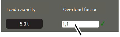
- The "Hoist profile parameter" window appears.
- In the "Overload factor" field, enter a factor through which the present test load will become an overload.
- Click on the "Write PLC" button.
Lifting the test load
- Observe the applicable occupational health and safety regulations and lift the test load.
- The overload protection must trigger.
- The display on the LED matrix display flashes.
- Set down the test load.
Resetting the overload protection
- Switch off the crane at the circuit isolator or mains switch.
- Wait 60 s.
- Switching the crane on again
- ABUControl will restart.
- The overload factor will be reset again.
Maintenance
This section applies to anyone who maintains, repairs or modifies the crane.
The end user of the crane is responsible for the selection and proper qualifications of the maintenance personnel.
Examples of qualified persons:
- Persons with comprehensive knowledge from specialist training in engineering and in the electrical systems of cranes.
- Persons with sufficient experience in the operation, installation and maintenance of cranes.
- Persons with comprehensive knowledge regarding the relevant technical rules, directives and safety regulations applicable in the respective country.
- Persons receiving regular training from ABUS.
ABUS assumes no liability for damage due to incorrectly performed maintenance work done by unqualified personnel.
ABUS recommends having the maintenance work performed by ABUS Service.
Use only original ABUS replacement parts. Otherwise, all warranty claims will be rendered invalid.
Instructions regarding safety when performing maintenance work
Observe the following safety information for all maintenance work on the crane with ABUControl:
- Switch off the mains switch. Secure the switch to ensure it cannot be turned back on accidentally.
- Open the fuse isolating link in the crane panel. Secure the fuse isolating link with a padlock so that it cannot be accidentally closed again.
- Use suitable lifting platforms and fall protection equipment.
- Adequately cordon off the operating range around the lifting platform.
- Switch off other cranes on the same crane track or cranes that are above or below the crane to be serviced. Secure the switches to ensure they cannot be turned back on accidentally. Other cranes could otherwise overturn the lifting platform or hit the crane to be serviced.
- Notify personnel in the area that maintenance work will be performed.
- Only trained electricians should work on the crane electrical system!
- Even after the emergency stop button has been pressed, life-threatening high voltages are still present in the crane control and in the trolley control.
These safety instructions apply particularly to the crane with ABUControl:
- Before working on the crane, disconnect the power line and wait at least 15 minutes until the voltage in the immediate circuits and the frequency converter has dissipated.
- Do not open the frequency converter housing.
Switching off the crane
Switching off crane with fuse isolating link
The fuse isolating link in the crane control fulfils the function of the circuit isolator. The entire crane can thus be disconnected from the current to the greatest possible extent.
This is primarily useful if the entire crane installation cannot be switched off with a general mains switch.
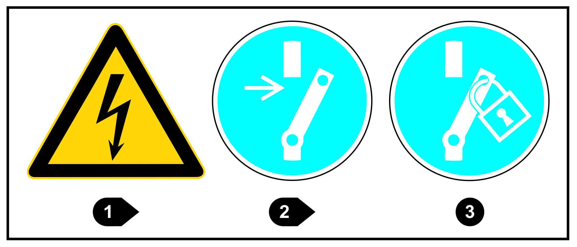
Product safety sign on the cover of the crane control for switching off the crane.
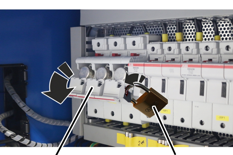
- Open crane control
- Observe the applicable occupational health and safety regulations and turn the fuse isolating link on the handle downwards.
- Secure fuse isolating link with padlock so that it cannot be accidentally closed again.
- Wait for 15 minutes while the voltage is dissipated.
- The crane is de-energised from the fuse isolating link onward. Voltage is still present up to the fuse isolating link. In special power circuits (e.g. for load lifting attachments), voltage may also still be present even if the fuse isolating link is open.
Changing fuses
Fuse link
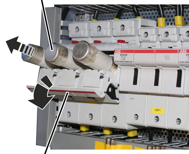
- Open out the fuse isolating link.
- Replace the fuse link.
- Close up the fuse isolating link.
Setting switching points for backup limiter and top hoist limiter
The wire rope hoist has a gear limit switch with three switching points.
The switching points for the top hoist limiter and the backup limiter placed above it are set and sealed at the factory.
If required, (e.g. if the load hook cannot be run right up to the top due to a crosshead), after changing the wire rope or after repairs, the switching point for the top hoist limiter may need to be reset.
Determining switching points
Switching point
Backup limiter C1
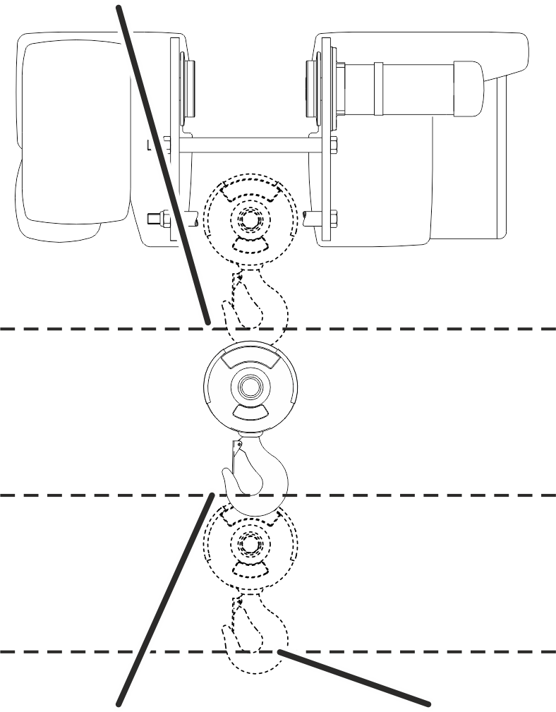
- The hook headroom (dimension C) is principally the highest position that the load hook may travel to without damaging the wire rope. A certain safety buffer is factored into this.
- The hook headroom (dimension C) is always the distance between the lower edge of the wheel on the wire rope hoist and the inner edge of the load hook.
- The hook headroom (dimension C) always refers to a standard series load hook. In the case of larger or smaller load hooks, see the wire rope data sheet for details of the hook headroom.
- The switching point for the backup limiter is designated as C1 and lies slightly above the hook headroom. This is the absolute uppermost position up to which the load hook may move without damaging the wire rope.
- The switching point for the top hoist limiter is designated as C2 and lies slightly below the hook headroom.
- Both switching points (C1 and C2) each have two alternative reference edges: A1 and A2 (distance between one of the edges on the wire rope hoist that are easily accessible from below and the axis of the deflection roller on the bottom block), as well as B1 and B2 (distance between one of the edges on the wire rope hoist that are easily accessible from below and the and the upper edge of the bottom block). These additional dimensions can be used as an alternative to the hook headroom and can make measuring easier. They are also independent of the load hook size and can thus be used with smaller or larger load hooks.
- Select the appropriate reference edge on the wire rope hoist and on the bottom block from the following drawing.
- Read the dimensions C1 and C2, or alternatively A1 and A2 or B1 and B2, from the following table.
Reference edges on the wire rope hoist according to type:
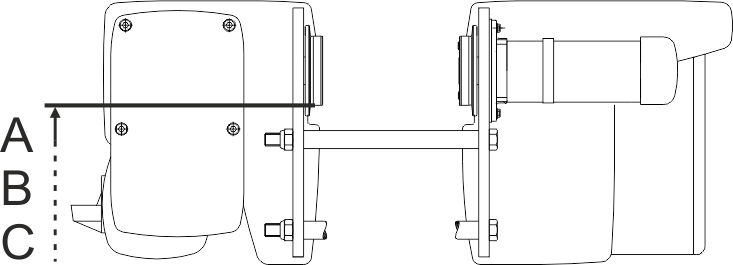
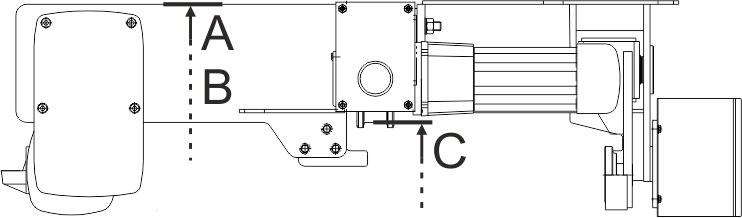
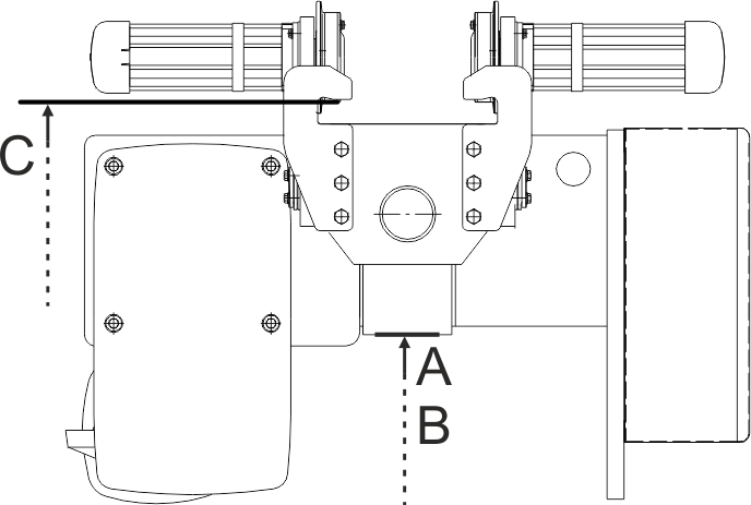
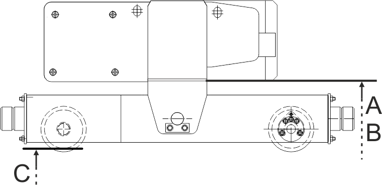
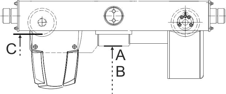
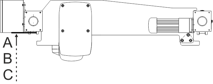
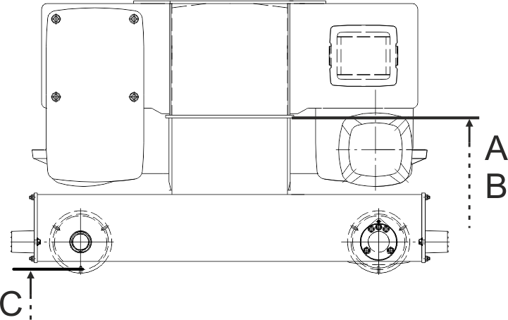
Reference edges on the bottom block:
Hook headroomBackup limiter switching point
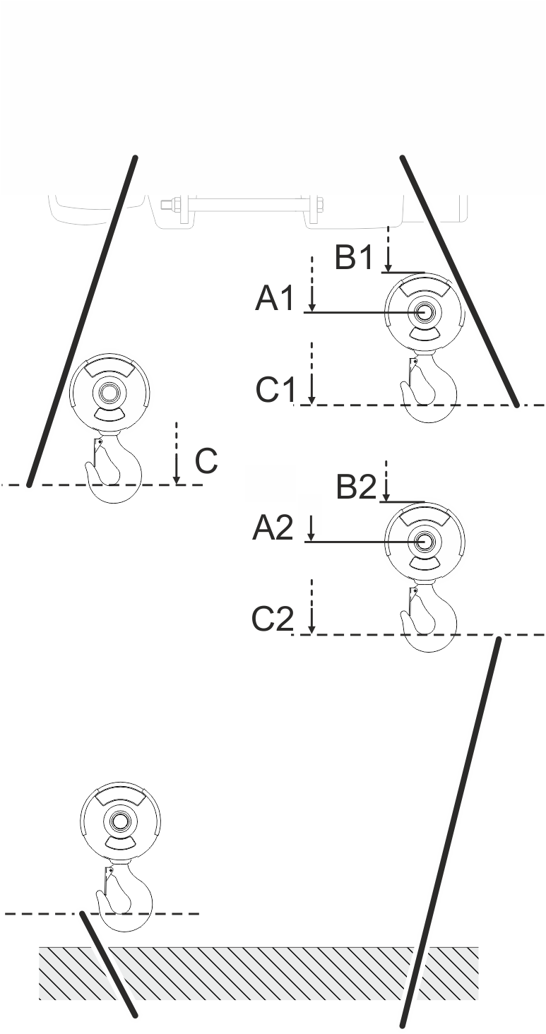
Fundamentally:
- 146 rotations of the adjusting screw completely rotate the control cam on the gear limit switch 360° once.
- How many millimetres of hook path correspond to one rotation of the adjusting screw is specified in the following table.
- Rotating the adjusting screw to the right moves the switching point downwards, rotating the adjusting screw to the left moves the switching point upwards.
- How many millimetres of hook path the load hook travels in the dead range of the Microswitch (switching hysteresis) is specified in the following table.
Backup limiter |
Top hoist limiter |
Dead range (switching hysteresis) |
Hook path per rotation of the adjusting screw |
|||||||||
|---|---|---|---|---|---|---|---|---|---|---|---|---|
Type |
Size |
Reeving |
Track gauge [mm] |
Hook headroom |
A1 [mm] |
B1 [mm] |
C1 [mm] |
A2 [mm] |
B2 [mm] |
C2 [mm] |
||
E |
800 |
4/1 |
Up to 300 |
400 |
165 |
70 |
380 |
215 |
120 |
430 |
55 |
71 |
E |
1000 * |
2/1 |
Up to 300 |
567 |
210 |
105 |
525 |
310 |
205 |
625 |
120 |
154 |
E |
1000 * |
4/1 |
Up to 300 |
500 |
230 |
125 |
480 |
279 |
175 |
530 |
60 |
77 |
E |
2000 |
2/1 |
Up to 300 |
580 |
180 |
70 |
540 |
280 |
170 |
640 |
130 |
172 |
E |
2000 |
4/1 |
Up to 300 |
500 |
195 |
80 |
480 |
245 |
130 |
530 |
65 |
86 |
E |
3000 |
2/1 |
Up to 300 |
664 |
215 |
70 |
625 |
315 |
170 |
734 |
160 |
214 |
E |
3000 |
4/1 |
Up to 300 |
580 |
235 |
90 |
560 |
285 |
140 |
610 |
80 |
107 |
E |
5000 |
2/1 |
Up to 350 |
830 |
295 |
110 |
790 |
395 |
210 |
890 |
178 |
238 |
E |
5000 |
4/1 |
Up to 350 |
825 |
375 |
190 |
805 |
425 |
240 |
855 |
89 |
119 |
E |
6000 |
2/1 |
Up to 350 |
830 |
295 |
110 |
790 |
395 |
210 |
890 |
194 |
260 |
* The specified values apply for the GM 1000 compact and for the GM 1000 modular. The values are identical for both designs.
Only with E-design wire rope hoist with larger track gauge
This section only applies to wire rope hoists of the design "E" with a larger track gauge than given in the table above.
Calculating larger hook headroom
The hook headroom has to be enlarged as of a certain track gauge.
- Add the additional dimension from the above table to the hook headroom.
Track gauge |
Installation size 800 |
Installation size 1000 |
Installation size 1000 |
Installation size 2000 |
Installation size 2000 |
Installation size 3000 |
Installation size 3000 |
Installation size 5000 |
Installation size 5000 |
Installation size 6000 |
|---|---|---|---|---|---|---|---|---|---|---|
300 |
0 |
0 |
0 |
0 |
0 |
0 |
0 |
- |
- |
- |
350 |
49 |
39 |
45 |
43 |
53 |
62 |
80 |
0 |
0 |
0 |
400 |
98 |
78 |
89 |
86 |
106 |
124 |
160 |
76 |
74 |
76 |
450 |
146 |
117 |
134 |
129 |
159 |
187 |
240 |
152 |
148 |
152 |
500 |
195 |
156 |
178 |
172 |
212 |
249 |
320 |
228 |
222 |
228 |
550 |
- |
- |
- |
- |
265 |
311 |
401 |
304 |
296 |
304 |
600 |
- |
- |
- |
- |
318 |
373 |
481 |
380 |
370 |
380 |
650 |
- |
- |
- |
- |
371 |
435 |
561 |
456 |
444 |
456 |
700 |
- |
- |
- |
- |
424 |
498 |
641 |
532 |
518 |
532 |
Backup limiter |
Top hoist limiter |
Dead range (switching hysteresis) |
Hook path per rotation of the adjusting screw |
||||||||
|---|---|---|---|---|---|---|---|---|---|---|---|
Type |
Size |
Reeving |
Hook headroom |
A1 [mm] |
B1 [mm] |
C1 [mm] |
A2 [mm] |
B2 [mm] |
C2 [mm] |
||
S |
800 |
4/1 |
343 |
335 |
245 |
323 |
385 |
295 |
377 |
55 |
71 |
S |
1000 |
4/1 |
420 |
420 |
315 |
400 |
470 |
365 |
450 |
60 |
77 |
S |
2000 |
4/1 |
440 |
405 |
290 |
420 |
455 |
340 |
470 |
65 |
86 |
S |
3000 |
2/1 |
699 |
520 |
370 |
659 |
620 |
470 |
760 |
160 |
214 |
S |
3000 |
4/1 |
550 |
540 |
395 |
530 |
590 |
445 |
580 |
80 |
107 |
Backup limiter |
Top hoist limiter |
Dead range (switching hysteresis) |
Hook path per rotation of the adjusting screw |
||||||||
|---|---|---|---|---|---|---|---|---|---|---|---|
Type |
Size |
Reeving |
Hook headroom |
A1 [mm] |
B1 [mm] |
C1 [mm] |
A2 [mm] |
B2 [mm] |
C2 [mm] |
||
U |
5000 |
4/1 |
1132 |
270 |
80 |
1110 |
320 |
130 |
1160 |
89 |
119 |
U |
6000 |
2/1 |
1256 |
235 |
50 |
1215 |
335 |
150 |
1315 |
194 |
260 |
U |
6000 |
4/1 |
1241 |
260 |
70 |
1220 |
310 |
120 |
1270 |
97 |
130 |
U |
7000 |
2/1 |
1615 |
330 |
90 |
1575 |
430 |
190 |
1675 |
254 |
342 |
Backup limiter |
Top hoist limiter |
Dead range (switching hysteresis) |
Hook path per rotation of the adjusting screw |
|||||||||
|---|---|---|---|---|---|---|---|---|---|---|---|---|
Type |
Size |
Reeving |
Track gauge [mm] |
Hook headroom |
A1 [mm] |
B1 [mm] |
C1 [mm] |
A2 [mm] |
B2 [mm] |
C2 [mm] |
||
D |
800 |
4/1 |
144 |
170 |
80 |
125 |
220 |
130 |
175 |
55 |
71 |
|
D |
1000 |
4/1 |
195 |
190 |
85 |
175 |
240 |
135 |
225 |
60 |
77 |
|
D |
2000 |
2/1 |
295 |
160 |
50 |
255 |
260 |
150 |
355 |
130 |
172 |
|
D |
2000 |
4/1 |
215 |
175 |
60 |
195 |
225 |
110 |
245 |
65 |
86 |
|
D |
3000 |
2/1 |
315 |
190 |
45 |
275 |
290 |
150 |
375 |
160 |
214 |
|
D130 |
3000 |
4/1 |
260 |
230 |
85 |
240 |
280 |
134 |
290 |
80 |
107 |
|
D160 |
3000 |
4/1 |
260 |
225 |
80 |
240 |
275 |
129 |
290 |
80 |
107 |
|
D |
5000 |
2/1 |
440 |
240 |
50 |
400 |
340 |
150 |
500 |
178 |
238 |
|
D |
5000 |
4/1 |
160 |
385 |
285 |
100 |
365 |
335 |
150 |
415 |
89 |
119 |
D |
5000 |
4/1 |
200 |
385 |
305 |
120 |
355 |
170 |
||||
D |
5000 |
4/2 |
320 |
330 |
220 |
280 |
430 |
320 |
380 |
178 |
238 |
|
D |
6000 |
2/1 |
520 |
235 |
50 |
480 |
335 |
150 |
580 |
194 |
260 |
|
D |
6000 |
4/1 |
267 |
260 |
73 |
247 |
310 |
123 |
297 |
97 |
130 |
|
D |
6000 |
6/1 |
606 |
355 |
168 |
586 |
405 |
218 |
636 |
65 |
87 |
|
D |
7000 |
2/1 |
572 |
344 |
103 |
532 |
444 |
203 |
632 |
254 |
342 |
|
D |
7000 |
4/1 |
501 |
380 |
139 |
481 |
430 |
189 |
531 |
127 |
171 |
|
D |
7000 |
6/1 |
to 2000 |
717 |
520 |
280 |
690 |
570 |
330 |
745 |
85 |
114 |
D |
7000 |
6/1 |
from 2000 |
897 |
520 |
280 |
875 |
570 |
330 |
925 |
85 |
114 |
D |
7000 |
4/2 |
236 |
240 |
50 |
195 |
340 |
150 |
295 |
254 |
342 |
|
D |
7000 |
8/2 |
516 |
260 |
70 |
495 |
310 |
120 |
545 |
127 |
171 |
|
Backup limiter |
Top hoist limiter |
Dead range (switching hysteresis) |
Hook path per rotation of the adjusting screw |
||||||||
|---|---|---|---|---|---|---|---|---|---|---|---|
Type |
Size |
Reeving |
Hook headroom |
A1 [mm] |
B1 [mm] |
C1 [mm] |
A2 [mm] |
B2 [mm] |
C2 [mm] |
||
DA |
800 |
4/1 |
429 |
170 |
80 |
410 |
220 |
130 |
460 |
55 |
71 |
DA |
1000 |
4/1 |
520 |
190 |
85 |
500 |
240 |
135 |
550 |
60 |
77 |
DA |
2000 |
2/1 |
621 |
160 |
50 |
580 |
260 |
150 |
681 |
130 |
172 |
DA |
2000 |
4/1 |
544 |
175 |
60 |
520 |
225 |
110 |
570 |
65 |
86 |
DA |
3000 |
2/1 |
700 |
193 |
45 |
660 |
290 |
145 |
760 |
160 |
214 |
DA |
3000 |
4/1 |
620 |
225 |
80 |
600 |
275 |
130 |
650 |
80 |
107 |
DA |
5000 |
2/1 |
825 |
240 |
50 |
785 |
340 |
150 |
885 |
178 |
238 |
DA |
5000 |
4/1 |
813 |
285 |
100 |
795 |
335 |
150 |
845 |
89 |
119 |
DA160 |
6000 |
2/1 |
949 |
235 |
50 |
910 |
335 |
150 |
1010 |
194 |
260 |
DA200 |
6000 |
4/1 |
470 |
260 |
70 |
450 |
310 |
120 |
500 |
97 |
130 |
DA280 |
6000 |
4/1 |
832 |
260 |
70 |
810 |
310 |
120 |
860 |
97 |
130 |
DA280 |
6000 |
6/1 |
1068 |
352 |
165 |
1050 |
400 |
215 |
1100 |
65 |
87 |
DA200 |
7000 |
2/1 |
1284 |
345 |
105 |
1245 |
445 |
205 |
1345 |
254 |
342 |
DA |
7000 |
4/1 |
913 |
375 |
135 |
895 |
425 |
185 |
943 |
127 |
171 |
DA |
7000 |
6/1 |
1370 |
515 |
275 |
1350 |
565 |
325 |
1400 |
85 |
114 |
Backup limiter |
Top hoist limiter |
Dead range (switching hysteresis) |
Hook path per rotation of the adjusting screw |
||||||||
|---|---|---|---|---|---|---|---|---|---|---|---|
Type |
Size |
Reeving |
Hook headroom |
A1 [mm] |
B1 [mm] |
C1 [mm] |
A2 [mm] |
B2 [mm] |
C2 [mm] |
||
DQA |
2000 |
2/1 |
525 |
125 |
10 |
485 |
225 |
110 |
585 |
130 |
172 |
DQA |
2000 |
4/1 |
445 |
140 |
30 |
425 |
190 |
80 |
475 |
65 |
86 |
DQA |
3000 |
2/1 |
639 |
190 |
40 |
600 |
290 |
140 |
700 |
160 |
214 |
DQA |
3000 |
4/1 |
555 |
210 |
65 |
535 |
260 |
115 |
585 |
80 |
107 |
DQA |
5000 |
2/1 |
810 |
275 |
90 |
770 |
375 |
190 |
870 |
178 |
238 |
DQA |
5000 |
4/1 |
712 |
265 |
75 |
690 |
315 |
125 |
740 |
89 |
119 |
DQA |
6000 |
2/1 |
870 |
335 |
150 |
830 |
435 |
250 |
930 |
194 |
260 |
DQA |
6000 |
4/1 |
745 |
250 |
60 |
725 |
300 |
110 |
775 |
97 |
130 |
DQA350 |
7000 |
4/1 |
970 |
375 |
135 |
950 |
425 |
185 |
1000 |
127 |
171 |
Backup limiter |
Top hoist limiter |
Dead range (switching hysteresis) |
Hook path per rotation of the adjusting screw |
|||||||||
|---|---|---|---|---|---|---|---|---|---|---|---|---|
Type |
Size |
Reeving |
Track gauge [mm] |
Hook headroom |
A1 [mm] |
B1 [mm] |
C1 [mm] |
A2 [mm] |
B2 [mm] |
C2 [mm] |
||
Z |
5000 |
4/2 |
413 |
490 |
300 |
375 |
590 |
400 |
475 |
178 |
238 |
|
Z |
5000 |
8/2 |
631 |
505 |
315 |
610 |
555 |
365 |
660 |
89 |
119 |
|
Z |
6000 |
4/2 |
414 |
485 |
300 |
375 |
585 |
400 |
475 |
194 |
260 |
|
Z280 |
6000 |
8/2 |
638 |
450 |
310 |
620 |
550 |
360 |
670 |
97 |
130 |
|
Z350 |
6000 |
8/2 |
643 |
450 |
260 |
625 |
500 |
310 |
675 |
97 |
130 |
|
Z |
7000 |
4/2 |
668 |
525 |
285 |
630 |
625 |
385 |
730 |
254 |
342 |
|
Z |
7000 |
6/2 |
to 2000 |
717 |
522 |
281 |
697 |
572 |
331 |
747 |
170 |
228 |
Z |
7000 |
6/2 |
from 2000 |
897 |
522 |
281 |
877 |
572 |
331 |
927 |
170 |
228 |
Z |
7000 |
8/2 |
915 |
525 |
284 |
895 |
575 |
334 |
945 |
127 |
171 |
|
Z |
7000 |
10/2 |
960 |
482 |
241 |
940 |
532 |
291 |
990 |
102 |
137 |
|
Z |
7000 |
12/2 |
1378 |
761 |
482 |
1358 |
811 |
532 |
1408 |
85 |
114 |
|
Backup limiter |
Top hoist limiter |
Dead range (switching hysteresis) |
Hook path per rotation of the adjusting screw |
||||||||
|---|---|---|---|---|---|---|---|---|---|---|---|
Type |
Size |
Reeving |
Hook headroom |
A1 [mm] |
B1 [mm] |
C1 [mm] |
A2 [mm] |
B2 [mm] |
C2 [mm] |
||
ZA |
5000 |
8/2 |
1195 |
495 |
305 |
1175 |
545 |
355 |
1225 |
89 |
119 |
ZA280 |
6000 |
8/2 |
1253 |
495 |
305 |
1235 |
545 |
355 |
1285 |
97 |
130 |
ZA350 |
6000 |
8/2 |
1163 |
445 |
255 |
1145 |
495 |
305 |
1195 |
97 |
130 |
ZA |
7000 |
6/2 |
1370 |
515 |
275 |
1350 |
565 |
325 |
1400 |
170 |
228 |
ZA |
7000 |
8/2 |
1430 |
515 |
275 |
1410 |
565 |
325 |
1460 |
127 |
171 |
ZA |
7000 |
10/2 |
1312 |
480 |
240 |
1290 |
530 |
290 |
1340 |
102 |
137 |
Travelling to the backup limiter switching point
The backup limiter switching point may only be adjusted by a qualified person for service purposes.
Dimensions A1, B1, C1
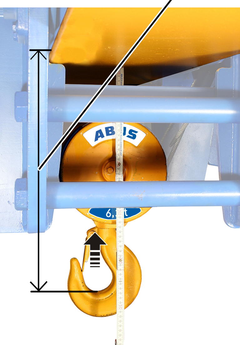
- Bypass top hoist limiter manually, so that the backup limiter can be travelled to.
- Raise the load hook up to dimension A1, B1 or C1.
Only with gear limit switch "GGS"
Detaching seals
Seals
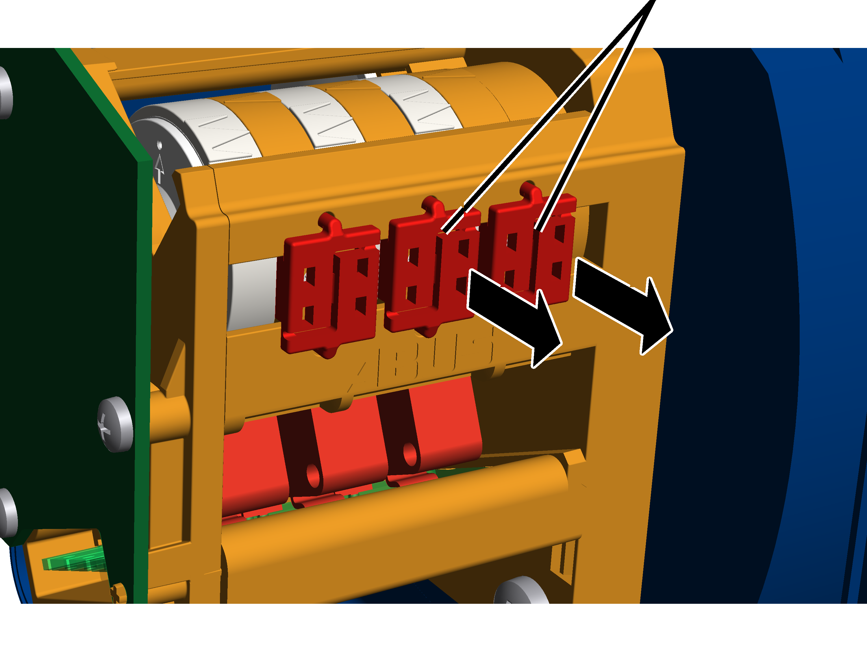
- Open the housing cover of the hoist limit switch enclosure on the cable drum.
- Press the seals apart in the centre with a screwdriver and remove them.
Setting backup limiterThe backup limiter is set with the right adjusting screw. White pointer of cam ringOrange pointer 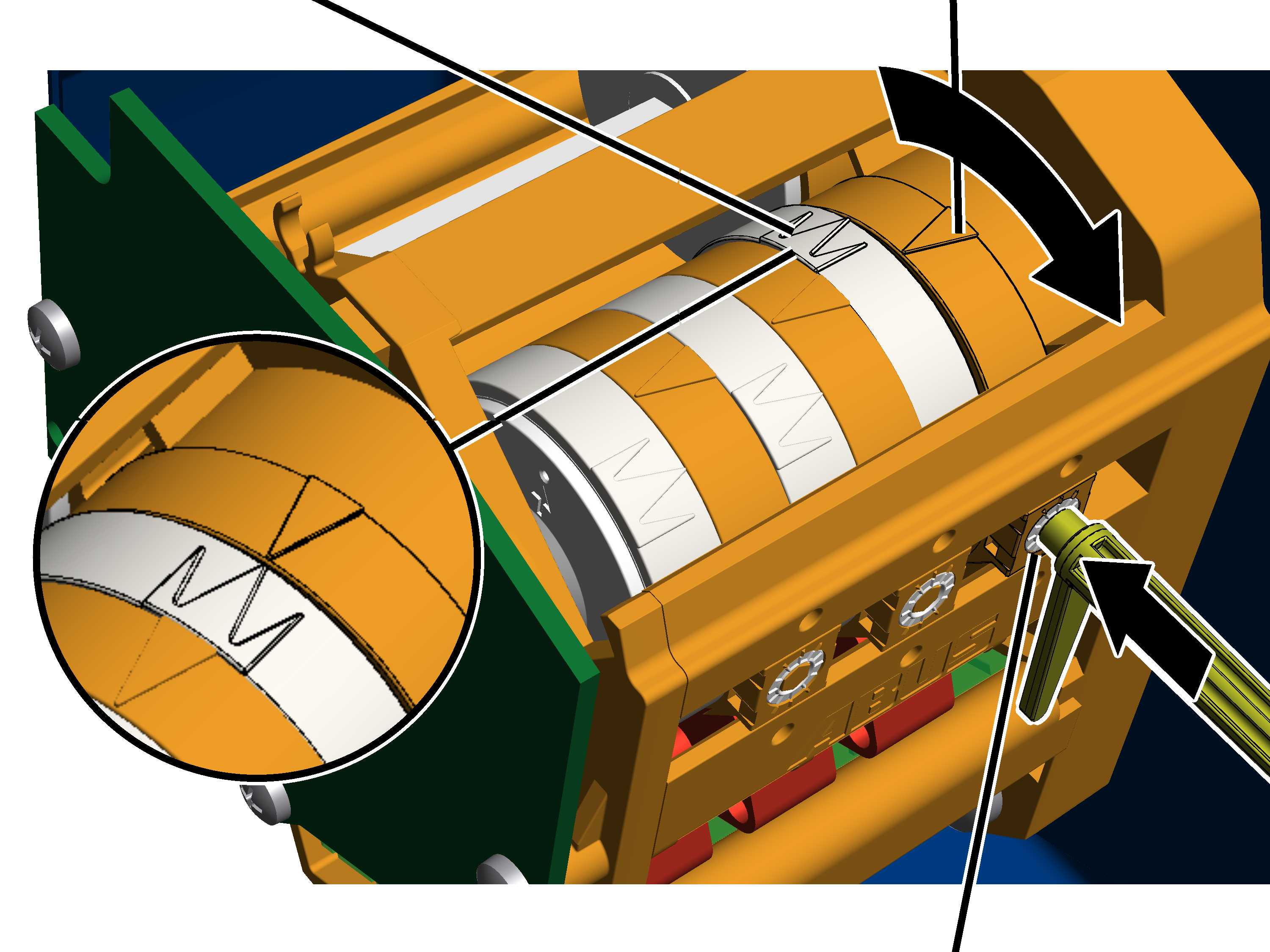
Alternatively, a hexagon wrench key size 3.0 (ideally with rotary plate) can be used. An electrically operated screwdriver may NOT be used.
|
|---|
ABUControl switches off the main conductor of the crane at this switching point. This switching point is only activated if the top hoist limiter has not switched (e.g. because it is faulty). 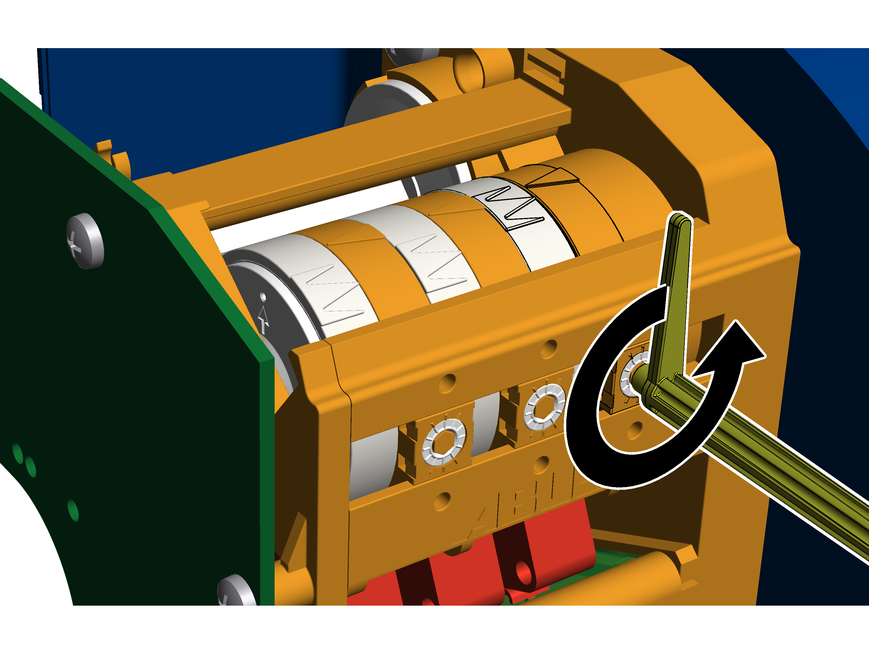
Travelling to the switching point of the top hoist limiter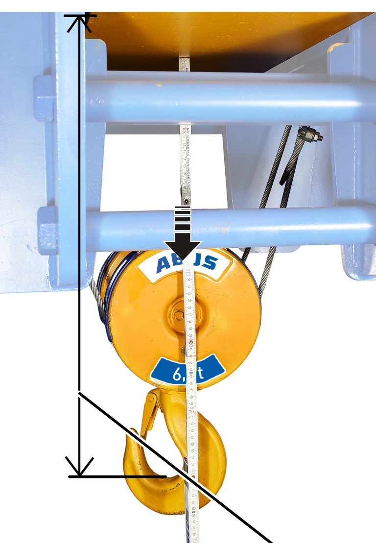
|
|---|
Setting top hoist limiterThe top hoist limiter is set with the middle adjusting screw. White pointer of cam ringOrange pointer 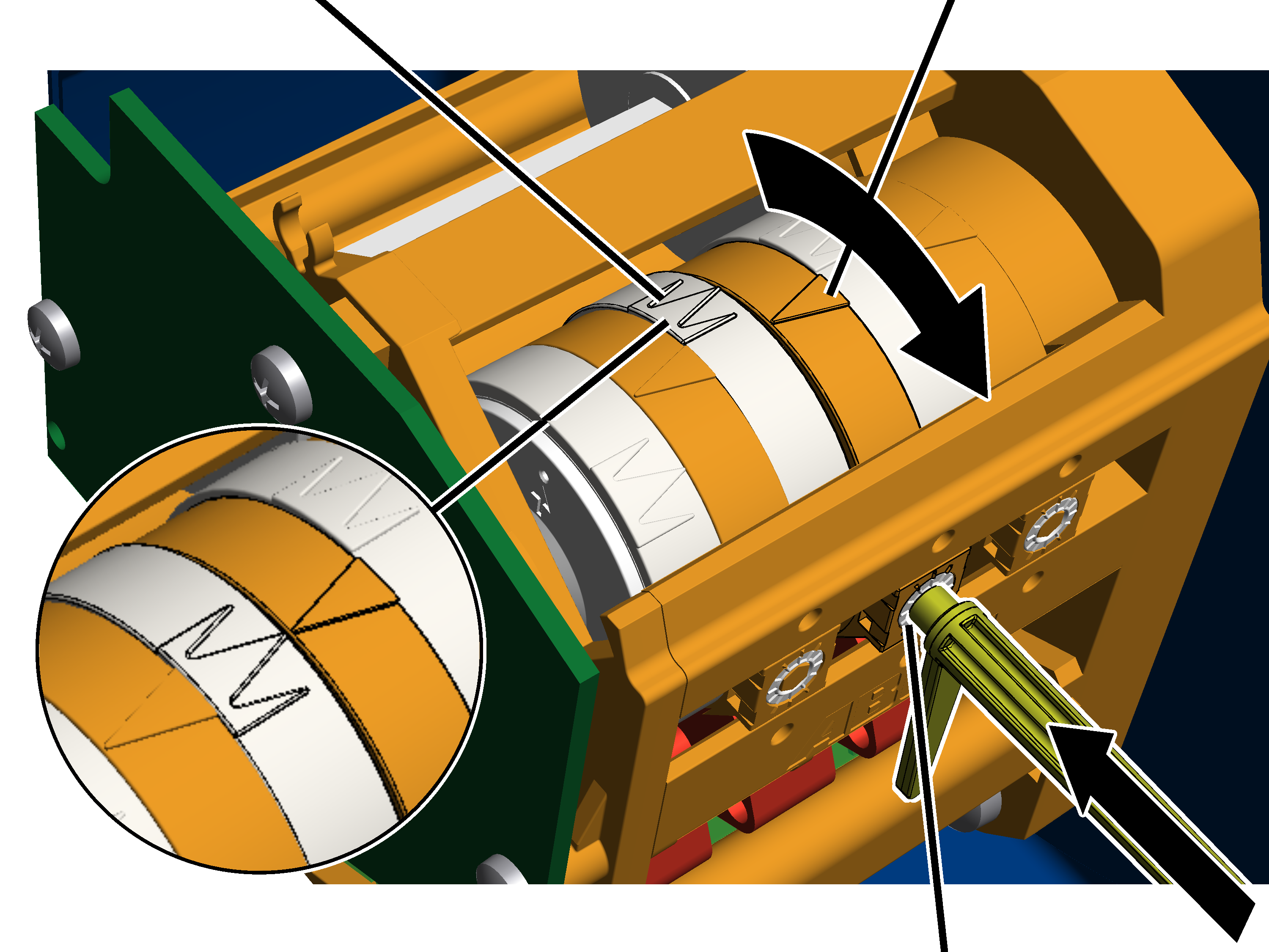
Alternatively, a hexagon wrench key size 3.0 (ideally with rotary plate) can be used. An electrically operated screwdriver may NOT be used.
The middle white arrow shows the exact position of the switching point; the two white arrows to the left and right of it indicate the start and end of the switching phase (switching hysteresis).
|
|---|
At this switching point the load hook stops during normal operation after it has previously braked. The braking distance is automatically determined by ABUControl in the next step. |
Only with "Kübler" gear limit switch
Setting backup limiter
The backup limiter is set with the backmost adjusting screw.
Control camMicroswitch
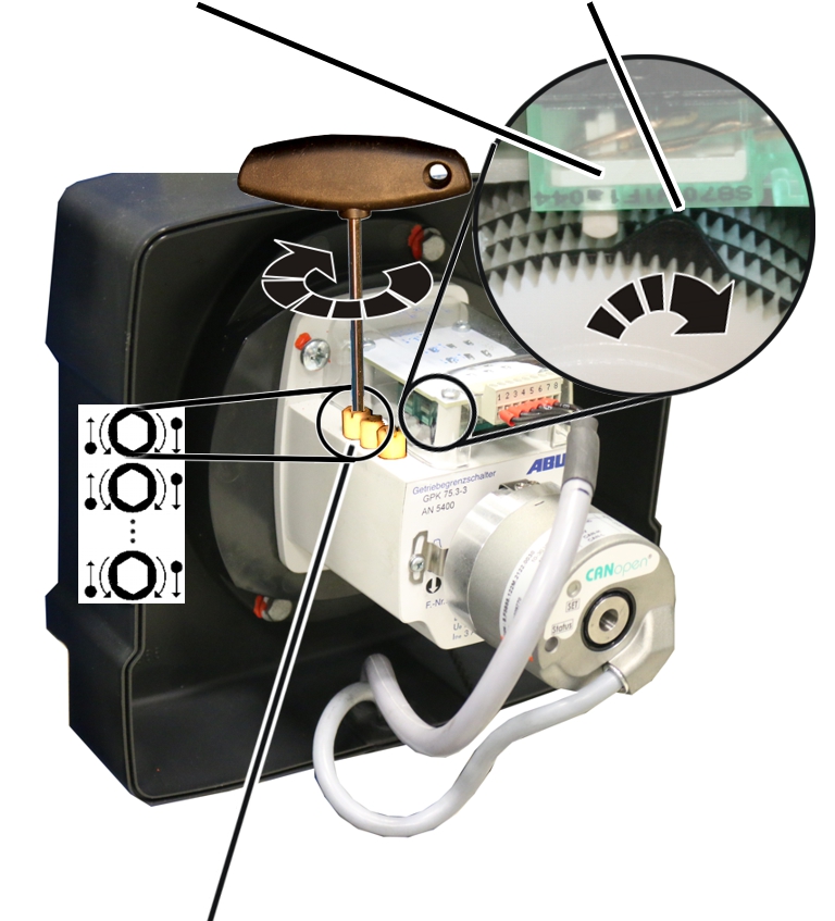
- If necessary: Turn the adjusting screw until the control cam is to the left of the Microswitch. It should not be either directly on or to the right of the microswitch.
- Turn the adjusting screw to the right until the control cam presses in a clockwise direction against the Microswitch and an audible click is heard.
- ABUControl switches off.
- The switching point for the backup limiter is now set.
ABUControl switches off the main conductor of the crane at this switching point. This switching point is only activated if the top hoist limiter has not switched (e.g. because it is faulty).
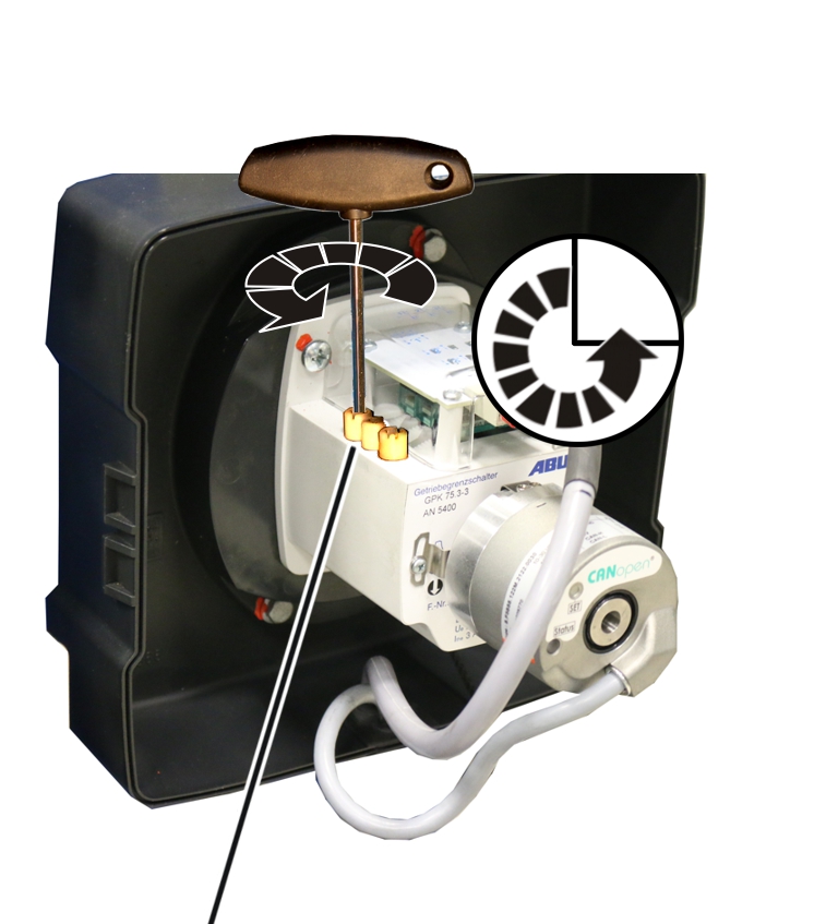
- Turn the adjusting screw three-quarters of a turn to the left.
- The Microswitch switches again, ABUControl switches on again.
- Lower the load hook slightly.
- Turn the adjusting screw three-quarters of a turn back to the right.
Travelling to the switching point of the top hoist limiter
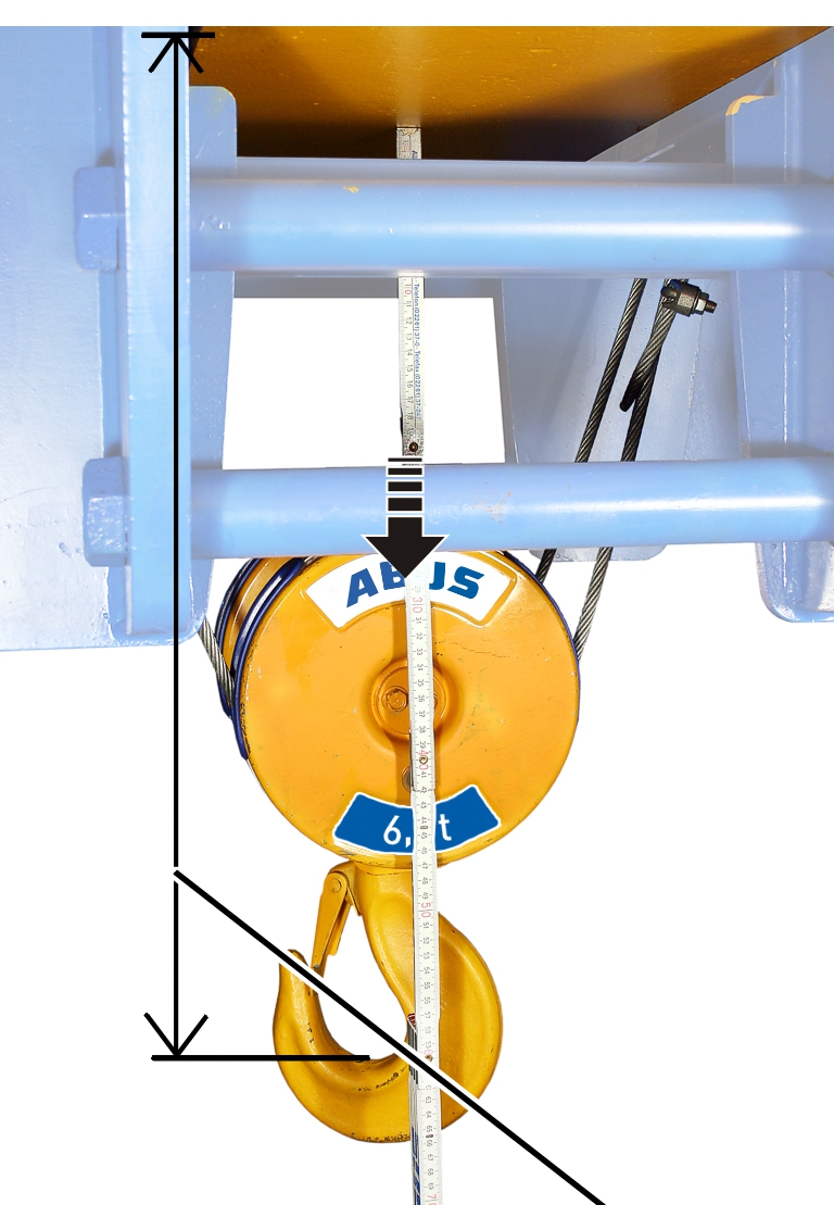
- Move the load hook up to dimension A2, B2 or C2.
Setting top hoist limiter
The top hoist limiter is set with the adjusting screw second from the back.
Adjusting screw
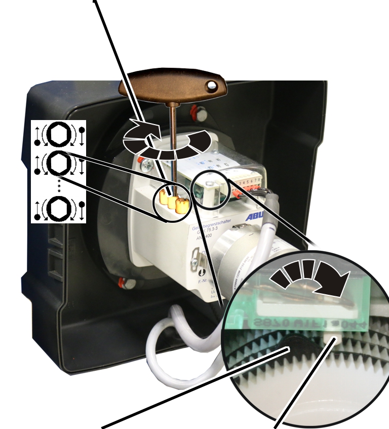
- If necessary: Turn the adjusting screw until the control cam is to the left of the Microswitch. It should not be either directly on or to the right of the microswitch.
- Turn the adjusting screw to the right until the control cam presses in a clockwise direction against the Microswitch and an audible click is heard.
- The switching point for the highest hook position is now set. At this switching point the load hook stops during normal operation after it has previously braked. The braking distance is automatically determined by ABUControl in the next step.
Determining braking distance
In normal operation, the load hook brakes at a slow lifting speed before it stops at the highest hook position.
The braking distance is also determined automatically by ABUControl.
- Raise the load hook without load a few metres downwards.
- Lower the load hook with fast lifting speed upwards.
- At the highest hook position, the load hook halts.
Depending on how the switching point was changed, it may be that the load hook with fast lifting speed moves to the switching point and then suddenly stops there or that the load hook brakes earlier than is necessary and a long stretch moves only at slow lifting speed.
If the load hook has to travel a long way at slow lifting speed, the end position of the brake phase can be changed manually. See "Temporarily changing the end position of the brake phase of the hoist drive".
- ABUControl saves the new switching point of the highest hook position automatically and now calculates the necessary braking distance automatically.
During the next travel to the switching point:
- The load hook brakes (depending on the current lifting speed) shortly before the highest hook position at slow lifting speed.
- The load hook only still travels with slow lifting speed immediately before the switching point.
- The load hook stops at the switching point.
Checking the setting
- Lower the load hook.
- Lift the load hook at both slow and fast lifting speed and check whether it halts at the correct point.
Only with gear limit switch "GGS"
Sealing the adjusting screws
Seals
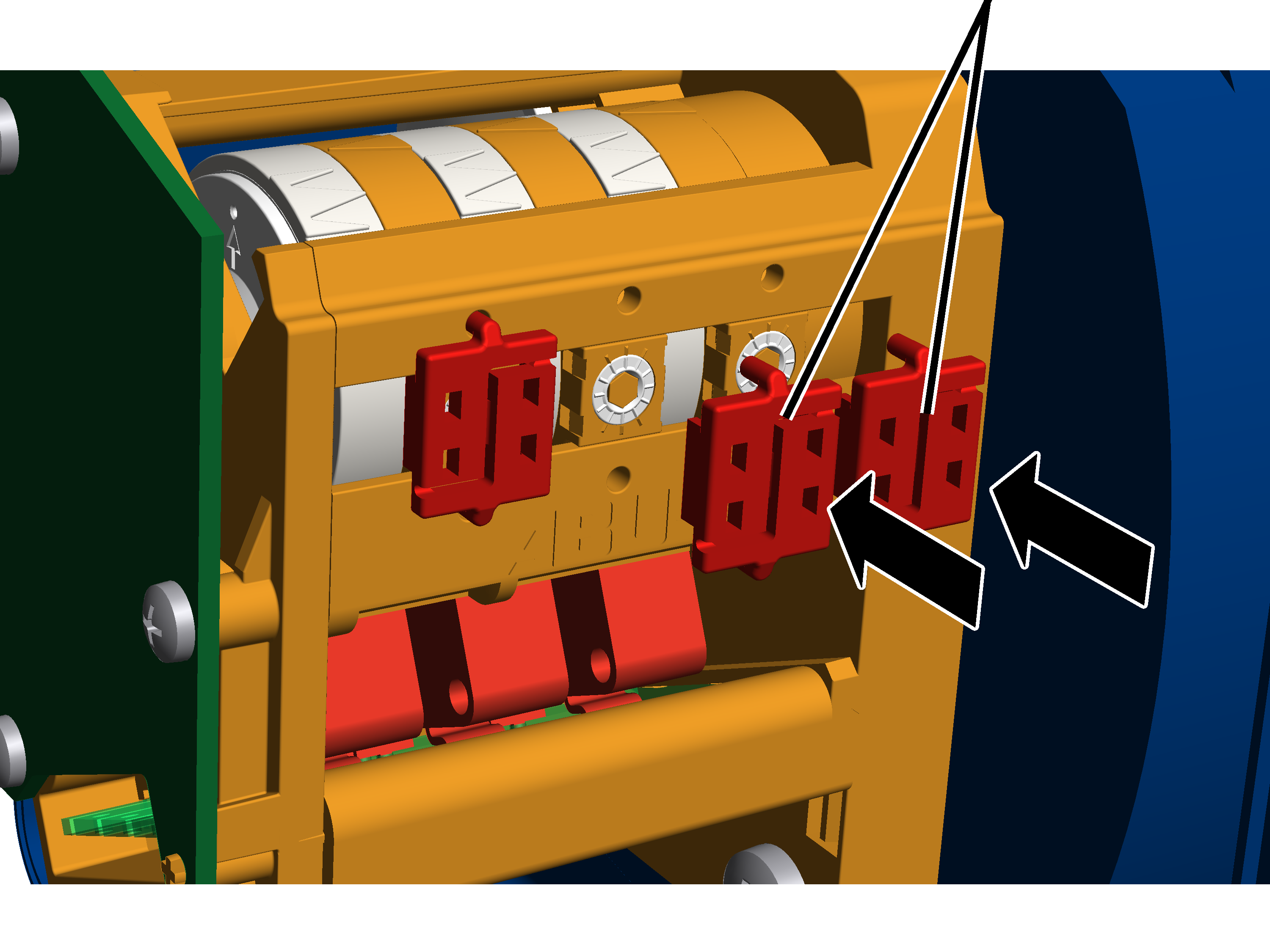
- Insert seals (2x) onto the adjusting screws and press them in.
Temporarily changing the end position of the brake phase of the hoist drive
In normal operation, ABUControl begins the brake phase of the hoist drive shortly before the switching point of the top/bottom hoist limiter. ABUControl individually calculates at which point the brake phase begins each time, depending on the current lifting speed. If the load hook travels upwards quickly, the brake phase begins earlier. If the load hook travels upwards slowly, the brake phase begins later.
Immediately before the hoist limiter switching point, the load hook only travels at slow lifting speed and continues to travels at slow lifting speed until the switching point is activated and the load hook stops. Normally, this is only a short stretch (a few centimetres).
However, if the switching point on the hoist limit switch is changed, for example, ABUControl does not yet recognise the resulting new end position and the new beginning of the brake phase. Due to this, it can happen that the load hook travels very far (if the switching point was significantly changed) only at slow lifting speed.
In such cases, the point to which the load hook only travels at slow lifting speed (end of the brake phase) can be temporarily changed. As soon as the switching point of the hoist limiter is activated, this manual change can however be overwritten so that the brake phase ends immediately before the hoist limiter switching point.
The process described here only changes (in KranOS) the end position of the brake phase of ABUControl temporarily. The hoist limiter switching point is not changed because of this.
For this work step, access from a laptop or tablet computer to KranOS is necessary. The user "Service" (user level [2]) must be logged in.
Opening the hoist limiter settings
Overview: Navigation in KranOS |
|---|
User "SERVICE" 🡪 "Hoist" 🡪 "Hoist calibration" |
- Log in to KranOS with user "Service" (user level [2]). See "Logging into and registering in KranOS".
- Select the desired hoist (e.g. hoist 1) in the main menu.
- The window for the requested hoist appears.
- Click on the "Hoist calibration" menu item in the "Settings" menu (three horizontal bars).
Setting the wire length
Input field for wire length, "Hoist limiter Top drive 1"Input field for wire length, "Hoist limiter Bottom drive 1"
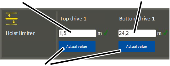
- The "Hoist calibration" window appears.
- In the input fields of the wire length, enter at which ones the load hook is to stop (the brake phase ends).
or
Move the load hook to the desired position and click on the "Actual value" button under the respective input field.
- The wire length (length of the uncoiled wire between cable drum and fixed point) is entered in the input fields. The hook position is not input!
- The wire length must be input separately for drive 1 and 2 (at twin hoist).
- Click on the "Write PLC" button.
- The set values are saved.
During lifting and lowering:
- ABUControl begins the brake phase of the hoist drive shortly before the set values. The point at which the brake phase begins is calculated by ABUControl individually each time, depending on the current lifting speed.
During the next travel to the top/bottom hoist limiter switching point:
- The previous setting is overwritten.
- Now ABUControl brakes the hoist drive again, so that the load hook moves immediately before the hoist limiter switching point only with slow lifting speed.
Switching between radio remote control and pendant control
If the crane is additionally equipped for radio remote control with a mobile control with pendant control, the pendant control can be used as necessary (e.g. when the radio transmitter is not available).
This requires that several bush multipoint connectors be reconnected in the crane panel.
Note:
When using a pendant control, a continuous movement profile is automatically activated. This cannot be changed in KranOS. The movement profile set in KranOS applies only to operation via the radio remote control.
Detaching the coupling from the receiver
Bush multipoint connector X2
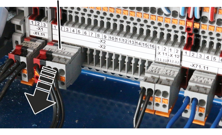
- Open the crane panel.
- Find bush multipoint connector X2.
- Detach bush multipoint connector.
Inserting coupler plug from pendant control
The bush multipoint connectors from the pendant control have already been guided into the crane panel and laid ready there.
Bush multipoint connector X2 12
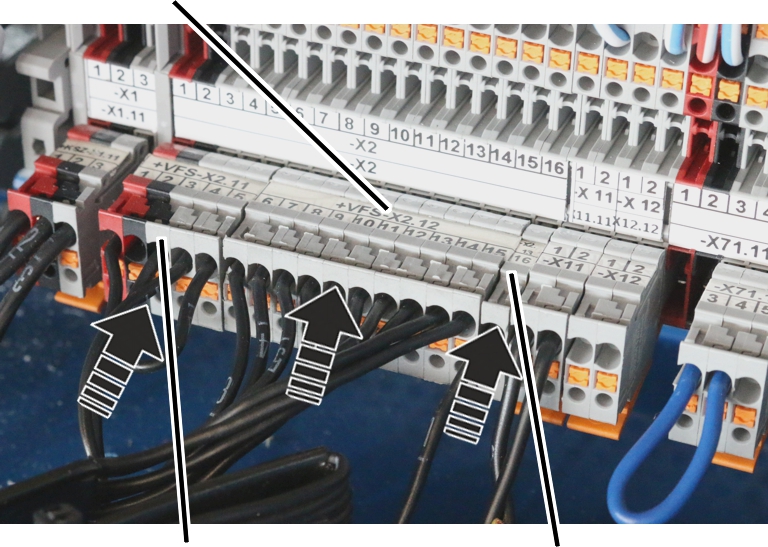
- Insert bush multipoint connector from pendant control:
- Bush multipoint connector X2.11 (terminal 1 to 5)
- Bush multipoint connector X2.12 (terminal 6 to 15)
- Bush multipoint connector X2.13 (terminal 16 to 27. Depending on the crane equipment, only individual terminals may be available and not all those described here)
- Bush multipoint connector X2.14 (terminal 28 to 38. Depending on the crane equipment, only individual terminals may be available and not all those described here, or the bush multipoint connector may be entirely omitted)
Replacing the wire rope
This section describes the work steps that must be performed with ABUControl during the replacement of the wire rope on a wire rope hoist. The work steps that must be performed on the wire rope hoist are described in the wire rope hoist product manual.
The figures show the work process on the GM modular wire rope hoist. The procedure on the other wire rope hoists does not differ significantly.
Preparing for wire rope replacement
- Move the load hook under the upper limit switch range. The switching point of the top hoist limiter must NOT be pressed.
- Measure, and note the position of the load hook.
This makes adjusting the hoist limit switch after replacing the wire rope in many cases unnecessary.
Only for ABUControl with contactor control or for twin hoist
In order for the wire rope to be unwound from the cable drum using a motor, the hoist limit switch must be removed. Otherwise the cable drum will stop at the lowest hook position.
Removing the hoist limit switch
The figures show the gear limit switch "GPK". The procedure on the gear limit switch "GGS" does not differ significantly.
Hoist limit switchPins on the cable drum
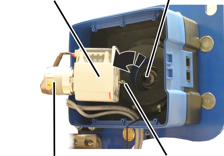
- Open the hoist limit switch housing.
- Unscrew and remove screws (2x).
- Pull off the hoist limit switch.
- Leave the shaft of the hoist limit switch in the same position, and do not turn it.
This makes adjusting the hoist limit switch after replacing the wire rope in many cases unnecessary.
If the shaft is accidentally twisted, the message "F_ _ 34 Wire rope change: Absolute rotary encoder 1 not removed" or "F_ _ 33 Wire rope change: Absolute rotary encoder 2 not removed" is displayed.
- Secure the hoist limit switch to ensure it does not fall down or hang from the connection cables.
Only with wire rope hoist with wire rope angle follower
This section applies only if an inclinometer is mounted on a wire rope angle follower on the wire rope hoist. This is the case for wire rope hoist D with a reeving of 4/2 or 8/2 and for wire rope hoist Z with an inclinometer. For other wire rope hoist models with an inclinometer but without a wire rope angle follower, please skip this section.
- Dismantle the inclinometer before the wire rope is replaced. See "Preparing the wire rope angle follower" in section "Installing and connecting the inclinometer"".
- Then remove the wire rope from the wire rope angle follower.
This means that the wire rope angle follower is not damaged when replacing the wire rope.
- Clean the wire rope angle follower if necessary.
The inclinometer can become soiled due to the lubricant on the wire rope.
If a connecting sleeve is used when replacing the wire rope, the wire rope angle follower should still be removed to prevent damage.
Activating the wire rope change on ABUControl
The wire rope changeover on ABUControl must be activated using a plug-in coupler in the trolley control panel or in KranOS. This is also necessary if the hoist limit switch has been removed (only required for contactor control or twin hoists), so that the cable drum can be driven by the motor.
Either activate the wire rope change by coupling:
Pin multipoint connector for parking
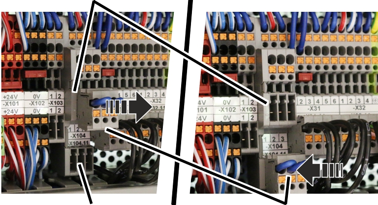
- Open trolley control.
- Search for prong terminal block ‑X104.
- Remove the coupling from the parking position (upper pin multipoint connector).
- Insert coupling on the upper pin multipoint connector.
- The wire rope change is activated. The cable drum can now be motor-run without ABUControl receiving a signal from absolute rotary encoder.
- The message "F_ _ 28: Wire rope change activated" is displayed.
- All the wear values for calculating the maximum acceptable wear are deleted so that the calculation for the new wire rope can start over.
- The speed of crane travel and trolley travel is limited to the slow travel speed.
- When the crane travel and trolley travel are moving, the horn sounds every second.
Or activate rope change via KranOS:
For this work step, access from a laptop or tablet computer to KranOS is necessary. The user "Service" (user level [2]) must be logged in.
Overview: Navigation in KranOS |
|---|
User "SERVICE" 🡪 "Hubwerk" |
- Log in to KranOS with user "Service" (user level [2]). See "Logging into and registering in KranOS".
- Select the desired hoist (e.g. hoist 1) in the main menu.
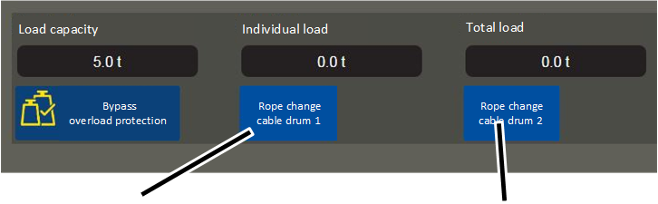
- The window for the requested hoist appears.
- Click on the "Rope change cable drum 1" button.
- The button's background turns green.
- The wire rope change is activated. The cable drum can now be motor-run without ABUControl receiving a signal from absolute rotary encoder.
- The message "F_ _ 28: Wire rope change activated" is displayed.
- All the wear values for calculating the maximum acceptable wear are deleted so that the calculation for the new wire rope can start over.
- The speed of crane travel and trolley travel is limited to the slow travel speed.
- When the crane travel and trolley travel are moving, the horn sounds every second.
Only with twin hoist
To change the wire rope on a twin hoist, it must be possible to control hoist drive 1 and hoist drive 2 separately from one another.
Activating wire rope change via coupling:
- Remove the coupling from the parking position (upper pin multipoint connector).
- Insert coupling on the upper pin multipoint connector:
- Coupling in left position (contacts 1, 2 and 3): The cable drum on hoist drive 1 can be controlled.
- Coupling in right position (contact 2, 3 and 4): The cable drum on hoist drive 2 can be controlled.
Activating wire rope change via KranOS:
- Click on the corresponding button in the window for the desired hoist:
- "Rope change cable drum 1": The button "Rope change cable drum 1" lights up green. The cable drum on hoist drive 1 can be controlled.
- "Rope change cable drum 2": The button "Rope change cable drum 2" lights up green. The cable drum on hoist drive 2 can be controlled.
Replacing the wire rope
- Allow the wire rope to run off the cable drum using the motor.
- Replacing wire rope. See the product manual for the wire rope hoist.
Only for ABUControl with contactor control or for twin hoist
Installing the hoist limit switch
- Move the load hooks to the position you noted previously.
- Connect the hoist limit switch to the pins on the cable drum.
- Screw the hoist limit switch tight.
- Check the positions of the switching points.
Only with wire rope hoist with wire rope angle follower
Installing the wire rope angle follower
- Install the wire rope angle follower. See "Installing and connecting the inclinometer".
Switching off the wire rope change
As soon as the wire rope has been changed:
- Remove the coupling from the lower pin multipoint connector on the prong terminal block -X104 and insert in the parking position (upper pin multipoint connector).
or
Click on the "Rope change cable drum 1" button.
- The wire rope change is switched off.
- The button's background is no longer green.
- To acknowledge the message "F_ _ 28: Wire rope change activated", press the emergency stop button or horn.
If the switching points have moved:
Normally, the adjustment of the hoist limit switch after replacing the wire rope can in many cases be omitted, since the position of the load hook was previously measured and then travelled to again. In special cases (e.g. if the wire rope is severely damaged or has been incorrectly rolled onto the cable drum), the switching points may need to be readjusted.
- Reset switching points for the bottom hoist limiter, the top hoist limiter and the backup limiter.
See "Setting switching points for backup limiter and top hoist limiter".
See "Setting switching point for the bottom hoist limiter".
- Reference the absolute rotary encoder again. See "Referencing the absolute rotary encoder".
If an inclinometer is fitted:
If an inclinometer is fitted, the wire rope angle follower must be calibrated. See "Calibrating the inclinometer".
Basic calibration of the load sensor
If the fixed point crosshead with load sensor or a single load sensor on the fixed point crosshead is replaced, the load sensor must undergo the basic calibration again. This calibration is a basic procedure has nothing to do with the calibration of the load measuring system with an increased test load, rather it represents the basic reference point for all load measurements. The load sensor must be completely free of load for this basic calibration. The wire rope and bottom block are also not permitted to affect the load sensor and must therefore be removed for the basic calibration.
After the basic calibration of the load sensor, the zero load must also be recalibrated and the load measuring system must additionally be recalibrated with an increased test load.
For a load measuring system with measurement bolt, the measurement bolt does not require a basic calibration. However, the calibration of the load measuring system with an increased test load is also necessary with a measurement bolt.
For this work step, access from a laptop or tablet computer to KranOS is necessary. The user "Service" (user level [2]) must be logged in.
Opening hoist calibration
Overview: Navigation in KranOS |
|---|
User "SERVICE" 🡪 "Hoist" 🡪 "Hoist calibration" |
- Log in to KranOS with user "Service" (user level [2]). See "Logging into and registering in KranOS".
- Select the desired hoist (e.g. hoist 1) in the main menu.
- The window for the requested hoist appears.
- Click on the "Hoist calibration" menu item in the "Settings" menu (three horizontal bars).
Basic calibration of the load sensor
The area in the right of the "Hoist calibration" window is used for the basic calibration. This work step is necessary if the fixed point crosshead or the load sensor was exchanged.
The load sensor must be completely free of load. The wire rope and bottom block are not permitted to affect the load sensor. The rope socket must therefore be removed from the fixed point crosshead. The fixed point crosshead may not be jammed or subjected to other mechanical tension.
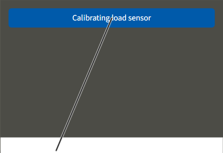
- The "Hoist calibration" window appears.
- Click the "Calibrating load sensor" button.
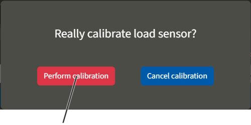
- A confirmation prompt appears.
- Click the "Perform calibration" button.
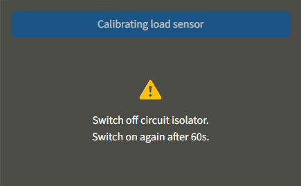
- The "Calibrating load sensor" button is greyed out.
- The calibration mode is activated.
- Switch off the crane at the circuit isolator or mains switch.
- Wait 60 s.
- Switch the crane on again.
- ABUControl will restart.
- The load sensor will additionally be calibrated during the restart.
Calibrating the load measuring system with an increased test load
After the basic calibration of the load sensor, the zero load must also be recalibrated and the load measuring system must additionally be recalibrated with an increased test load.
- Calibrate the load measuring system again with an increased test load. See "Calibrating the load measuring system with an increased test load".
Display status of crane axes
Information about the current status of all crane axes (crane travel, trolley travel, hoist) can be displayed in KranOS.
For this work step, access from a laptop or tablet computer to KranOS is necessary. The user "CUSTOMER" (user level ‚[1]) or "SERVICE" (user level [2]) must be logged in.
Displaying the crane axis
Overview: Navigation in KranOS |
|---|
User "CUSTOMER" or "SERVICE" 🡪 "Crane travel" |
User "CUSTOMER" or "SERVICE" 🡪 "Trolley travel" |
User "CUSTOMER" or "SERVICE" 🡪 "Hoist" |
Only crane axes that are actually available on the crane are displayed. Only components that are actually available on the crane are displayed in the window. |
- Log in to KranOS with user "CUSTOMER" (user level ‚[1]) or "SERVICE" (user level [2]). See "Logging into and registering in KranOS".
- Select the desired crane axis (e.g. crane travel) in the main menu.
- The window for the corresponding crane axis appears.
The windows differ from each other depending on the crane axis.
Crane travel:
Crane travel frequency converters -TA61 and -TA62Crane travel limit switch -B71
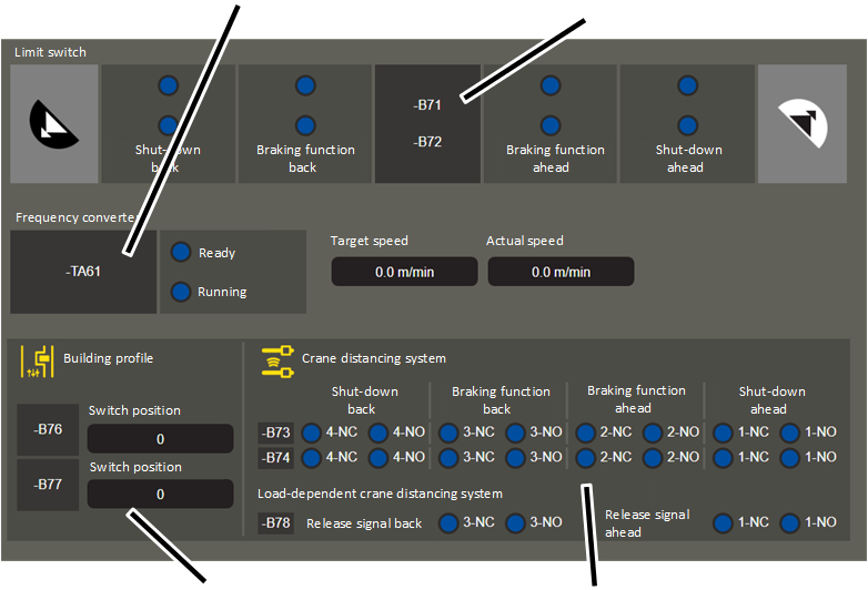
- Crane travel limit switch (-B71): The crane travel limit switch switch position is displayed here.
Green background: travel limit switch not triggered
Blue background: travel limit switch triggered.
The crane travel limit switches are used for a braking function and shut-down. In the direction of the crane track end, cross-type limit switches (-B71) are used; in the direction of another crane on the same run, reflective light barriers are used (instead of -B71, -B711 and -B712 as well as -B713 and -B714 are used).
- Additional crane travel limit switches (‑B72): In addition to ‑B71, each crane travel limit switch may be provided in duplicate for each switching point and direction of travel in order to enhance the safety of the system.
- Crane travel frequency converters (-TA61 and TA62): The status of the crane travel frequency converter is displayed here:
"Ready": The frequency converter is ready for operation.
"Running": The frequency converter is active so that the drive rotates.
"Target speed": Speed at which the drive is expected to rotate.
"Actual speed": Speed at which the drive rotates.
For cranes without electronic track guidance system, a joint frequency converter (-TA61) is used for both crane travel drives. For an electronic track guidance system or a 4-wheel crane travel drive, an additional frequency converter -TA62 is displayed.
- Cross-type limit switch for building profile control (‑B76 / ‑B77): The current switch position of the cross-type limit switch that is used for the building profile control is displayed here. Through the combination of both cross-type limit switches, each with six switching statuses, up to 36 positions can be recorded.
- Reflective light barriers for crane distancing system (-B73): The switching statuses of the reflective light barriers of the crane distancing system are displayed here.
With the crane distancing system, the crane brakes at low speed (braking function) or remains completely still (shut-down), once a set distance to another crane on the same run falls below the target.
For each switching point and every travel direction one reflective light barrier is used. ABUControl monitors the normally closed contact (NC) and the normally open contact (NO) or all reflective light barriers simultaneously.
Switching contact 1 is used for the shut-down forwards, switching contact 2 is used for the braking function forwards, switching contact 3 is used for the braking function backwards and switching contact 4 is used for the shut-down backwards.
The crane distancing system is frequently used to prevent cranes e.g. from exceeding a certain distance due to static reasons. The crane distancing system can also be jointly used with the anti-collision device (see crane travel limit switch -B71).
- Additional reflective light barriers for crane distancing system (-B74): In addition to -B73 every reflective light barrier can be available in duplicate for every switching point and every travel direction to increase system security.
- Light barrier for signal transmission for load-dependent crane distancing system (-B78):
If the crane distancing system is run load-dependently, the crane is decelerated and stopped as soon as a set distance to another crane on the same run is fallen short of and a load above a set value is simultaneously moved.
So that both controls in the crane and the other crane on the same run are known, whether the set load has just fallen below or been exceeded on the other crane, this information is transmitted with a light barrier between both cranes. Each crane has light barriers for signal transmission of the release signal, one as a transmitter and one as a receiver.
Which signal is currently present at the receiver is displayed here. Area 1 shows the release signal in the forwards direction. Area 3 shows the release signal in the backwards direction.
NC has a blue background, NO has a green background: The set load is fallen short of. The crane does not receive a release signal from the other crane on the same run.
NC has a green background, NO has a blue background: The set load has been exceeded. The crane receives a release signal from the other crane on the same run.
The load can be set in the advanced parameters. See "Setting advanced travel profile parameters (crane travel profile, trolley travel profile)".
Trolley travel:
Trolley travel frequency converter -TA41Trolley travel limit switch -B51
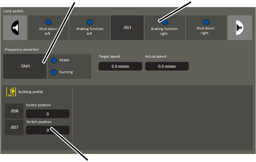
- Trolley travel limit switch (-B51): The switching position of the trolley travel limit switch is displayed here.
Green background: travel limit switch not triggered
Blue background: travel limit switch triggered.
- Trolley travel frequency converters (-TA41): The status of the trolley travel frequency converter is displayed here:
"Ready": The frequency converter is ready for operation.
"Running": The frequency converter is active so that the drive rotates.
"Target speed": Speed at which the drive is expected to rotate.
"Actual speed": Speed at which the drive rotates.
Cross-type limit switch for building profile control (‑B56 / ‑B57): The current switch position of the cross-type limit switch that is used for the building profile control is displayed here. Through the combination of both cross-type limit switches, each with six switching statuses, up to 36 positions can be recorded.
Hoist:
Hoist frequency converter ‑1TA21 and ‑2TA21Hoist limit switch -B31 and -B32
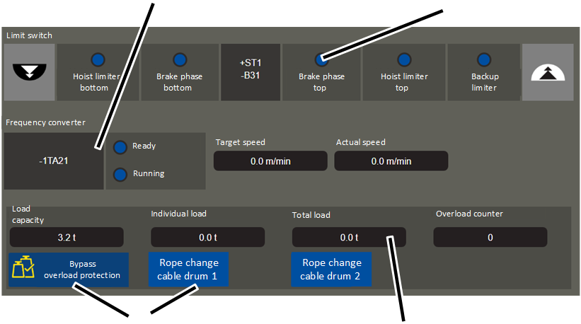
- Hoist limit switch (-B31): The hoist limit switch switching is displayed here.
Green background: hoist limit switch not triggered
Blue background: hoist limit switch triggered.
An additional hoist limit switch -B32 is used at a twin hoist for the second cable drum.
For hoists with contactor controls: The current switch position is only displayed while the hoist lifts or lowers. If the hoist is stopped, the switching points have a blue background.
- Hoist frequency converter (-1TA21): The status of the hoist frequency converter is displayed here:
"Ready": The frequency converter is ready for operation.
"Running": The frequency converter is active so that the drive rotates.
"Target speed": Speed at which the drive is expected to rotate.
"Actual speed": Speed at which the drive rotates.
An additional frequency converter ‑2TA21 is displayed at a twin hoist for the second cable drum.
Load display: The load measuring system measurement results are displayed here:
"Load capacity": Maximum load capacity of the hoist.
"Individual load": Currently measured load on the hoist.
"Total load": Total load on all hoists or on all cranes.
"Overload counter": Number of lifting motions with overload. The number always increases by 1 if the hoist lifts a load that is over the maximum load capacity of the crane.
- Button: The service work functions can be switched on here:
"Bypass overload protection": See "Bridging overload protection".
"Rope change cable drum": See "Replacing the wire rope".
Selecting movement profiles
Different movement profiles can be selected for the movements of all three crane axes (crane travel, trolley travel, lift/lower). The basic motion behaviour can be defined through this.
For this work step, access from a laptop or tablet computer to KranOS is necessary. The user "Service" (user level [2]) must be logged in.
Opening selection for movement profile
Overview: Navigation in KranOS |
|---|
User "SERVICE" 🡪 "Movement profile" |
- Log in to KranOS with user "Service" (user level [2]). See "Logging into and registering in KranOS".
- In the start window: Click on the "Movement profile" menu item in the "Settings" menu (three horizontal bars).
Selecting movement profile
Selection fields for movement profiles
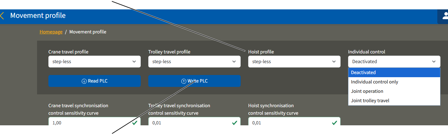
- The "Movement profile" window appears.
- The current settings are displayed.
- Select the desired movement profile in the crane axis:
- Step-less: The drive can be accelerated into the second level up to a maximum value with a two-step button or joystick as long as the button is held down. If the button or joystick switches back into the first level, the drive maintains the current speed. If the button or joystick is released, the speed is reduced.
- Two-step: The drive can be accelerated to a permanently set slow travel speed in the first level and to a permanently set fast travel speed in the second level with a two-step button or joystick.
- Linear analogue value: The drive can be continuously accelerated and braked with a proportional joystick. The further the joystick is activated, the faster the drive rotates. The relationship between the joystick and drive is linear.
Analogue value S curve: As before. The relationship between the joystick and drive is in the form of an S curve. This means that relatively a lot of motion is necessary on the joystick in the range around the zero point of the joystick (drive stationary), and relatively less on the upper and lower stop points of the joystick. Thus the crane can be very precisely controlled, particularly during slower movements.
- Click on the "Write PLC" button.
Only with tandem operation
- Log onto the partner crane and set the same movement profile in the "Movement profile" window.
If a different movement profile is set on the partner crane, the error message "F0026: Tandem operation: Different travel profiles" is displayed when tandem operation is activated.
Setting individual control for ABURemote transmitters
Only with ABURemote "Joystick" with individual control
With an ABURemote transmitter "Joystick" with individual control (transmitter with three joysticks), the individual control mode can be set in KranOS. See also ABURemote "Joystick" product manual.
For this work step, access from a laptop or tablet computer to KranOS is necessary. The user "CUSTOMER" (user level [1] or "SERVICE" (user level [2]) must be logged in.
Opening selection for movement profile
Overview: Navigation in KranOS |
|---|
User "CUSTOMER" or "SERVICE" 🡪 "Movement profile" |
- Log in to KranOS with user "CUSTOMER" (user level [1]) or "SERVICE" (user level [2]). See "Logging into and registering in KranOS".
- In the start window: Click on the "Movement profile" menu item in the "Settings" menu (three horizontal bars).
Setting individual control
"Individual control" selection field
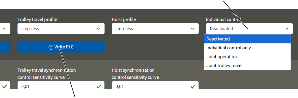
- The "Movement profile" window appears.
- The current setting is displayed.
- Select the desired value in the "Individual control" selection field.
- "Deactivated": The individual control is switched off. The middle joystick on the ABURemote transmitter is disabled.
- "Individual control only": The trolleys can be operated independently of each other. One joystick on the transmitter controls Trolley I, the other joystick on the transmitter controls Trolley II. The flip switch for joint operation is disabled.
- "Joint operation": The trolleys can be controlled independently of each other as previously described. In addition, the flip switch on the transmitter can be switched to joint operation. The right joystick then controls the two trolleys in joint operation, while the middle joystick is disabled.
- "Joint trolley travel": The trolleys can be controlled independently of each other as previously described. In addition, the flip switch on the transmitter can be switched to joint trolley travel. The right joystick then controls the joint trolley travel for both trolleys. The hoists of both trolleys remain independently operable with the middle and right-hand joystick.
- Click on the "Write PLC" button.
Note:
Selecting individual control mode increases braking distances. See the product manual "ABUS ABURemote Joystick radio remote control".
Temporarily bridging travel limit switch and hoist limiter
All travel limit switches and hoist limiters (excepting the backup limiter) can be temporarily bridged, e.g. for repairs.
For this work step, access from a laptop or tablet computer to KranOS is necessary. The user "Service" (user level [2]) must be logged in.
Opening the window for movement profiles
Overview: Navigation in KranOS |
|---|
User "SERVICE" 🡪 "Movement profile" |
- Log in to KranOS with user "Service" (user level [2]). See "Logging into and registering in KranOS".
- In the start window: Click on the "Movement profile" menu item in the "Settings" menu (three horizontal bars).
Bridging travel limit switch and hoist limiter
"Bypass all travel limit switches and hoist limiters" switch
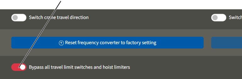
- The "Movement profile" window appears.
- Click the button "Bypass all travel limit switches and hoist limiters".
- The button's background turns red.
- All travel limit switches (trolley travel limit switches of all trolleys and crane travel limit switches in the form of cross-type limit switches, distance sensors, reflective light barriers as braking function and shut-down) and all hoist limiters (top and bottom hoist limiters of all hoists) as well as the building profile control, are bridged.
- Crane, trolley and hoist can run/lift at low speed.
- The message F0064 "All travel limit switches and hoist limiters bridged" is displayed.
- The bridging remains on until you switch it off again by pressing the button "Bypass all travel limit switches and hoist limiters".
- The bridging also remains switched on if the crane is switched off and then back on again.
Switching travel direction of crane and trolley
In some circumstances it may be necessary to switch the travel direction of the crane or trolley. This can be required, for example, if the crane was installed differently than was specified in the planning documents.
All specification related to travel directions are thereby switched. This applies, for example, to the buttons on the transmitter of the radio remote control, all displays in KranOS, the evaluated motion restrictors as well as cross-type limit switches and distance sensors, all error messages related to travel directions, etc.
For this work step, access from a laptop or tablet computer to KranOS is necessary. The user "Service" (user level [2]) must be logged in.
Opening the window for movement profiles
Overview: Navigation in KranOS |
|---|
User "SERVICE" 🡪 "Movement profile" |
- Log in to KranOS with user "Service" (user level [2]). See "Logging into and registering in KranOS".
- In the start window: Click on the "Movement profile" menu item in the "Settings" menu (three horizontal bars).
Switching travel direction of crane and trolley
"Switch crane travel direction" button"Switch trolley travel direction" button

- The "Movement profile" window appears.
- Click the button "Switch crane travel direction" or "Switch trolley travel direction".
- The button's background turns blue.
- All specifications related to travel directions for crane travel or trolley travel are switched.
- The switch of the travel direction is sustained and also remains saved if the crane is switched off and then back on again.
Setting synchronisation control
The synchronization control system for crane travel, trolley travel and lifting/lowering is factory set and adapted for the majority of situations.
If necessary, the maximum synchronisation deviation and the sensitivity curve can be adjusted to the on-site conditions.
For this work step, access from a laptop or tablet computer to KranOS is necessary. The user "Service" (user level [2]) must be logged in.
Opening the synchronisation control settings
Overview: Navigation in KranOS |
|---|
User "SERVICE" 🡪 "Movement profile" |
- Log in to KranOS with user "Service" (user level [2]). See "Logging into and registering in KranOS".
- In the start window: Click on the "Movement profile" menu item in the "Settings" menu (three horizontal bars).
Setting synchronisation control
"Crane travel synchronisation control sensitivity curve" and "Trolley travel synchronisation control sensitivity curve"
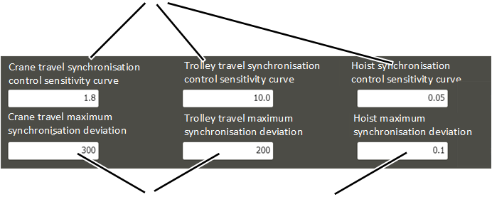
- The "Movement profile" window appears.
- The current settings of the synchronisation control are displayed.
- Modify the sensitivity curve for crane travel, trolley travel and lifting/lowering moderately in small steps when adapting it to the on-site conditions, and always test it again through a trial run.
The sensitivity curve can be set to between "0.01" and "10.0". The smallest value (factor 0.01) corresponds to a slow control response. As the factor increases, the sensitivity of the control response increases.
- Modify the maximum synchronisation deviation in millimetres in small steps when adapting it to the on-site conditions, and always test it again through a trial run.
The maximum synchronisation deviation is the maximum distance of the crane, trolley or load hook in joint or tandem operation.
- Click on the "Write PLC" button.
Restarting crane
Only with restart function of the crane
The function "Restart crane" is used to restart the crane by electrically disconnecting the supply voltage.
For this work step, access from a laptop or tablet computer to KranOS is necessary. The user "SERVICE" (user level [2]) must be logged in.
Opening the PLC diagnosis page
Overview: Navigation in KranOS |
|---|
User "SERVICE" 🡪 "PLC diagnosis" |
- Log in to KranOS with user "Service" (user level [2]). See "Logging into and registering in KranOS".
- In the start window: Click on the "PLC diagnosis" menu item in the "Settings" menu (three horizontal bars).
Restarting crane
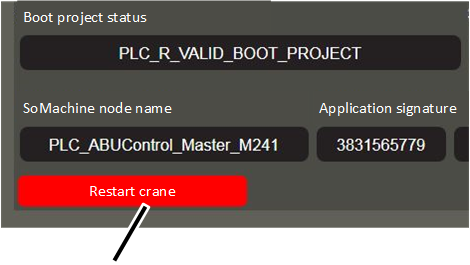
- The "PLC diagnosis" window appears.
- Click the "Restart crane" button.
- The operating voltage is briefly interrupted and then switched on again.
- The crane control is restarted.
Setting load-controlled switching points
Additional functions can be switched on the crane via load-controlled switching points. Outputs on the crane control can be used for this, which switch as soon as more than a certain load is lifted by the crane.
For the crane (total load) and for each hoist, up to two load-controlled switching points are available. The planning and electrical connection of the outputs is done according to the specific order. The setting of the loads for each switching point is performed in KranOS.
Two example applications for this function could be signal lamps (for example, under 85% of the maximum load capacity a green signal lamp lights up), or the control of a gripper (from 10% or more of the maximum load capacity the gripper is no longer permitted to open).
For this work step, access from a laptop or tablet computer to KranOS is necessary. The user "Service" (user level [2]) must be logged in.
Calling up settings for load-controlled switching points
Overview: Navigation in KranOS |
|---|
User "SERVICE" 🡪 "Load-controlled switching point" |
Only those hoists that are actually available on the crane are displayed in the window. |
- Log in to KranOS with user "Service" (user level [2]). See "Logging into and registering in KranOS".
- In the start window: Click on the "Load-controlled switching point" menu item in the "Settings" menu (three horizontal bars).
Setting switching points
Load-controlled switching points for craneLoad-controlled switching points for hoist 1
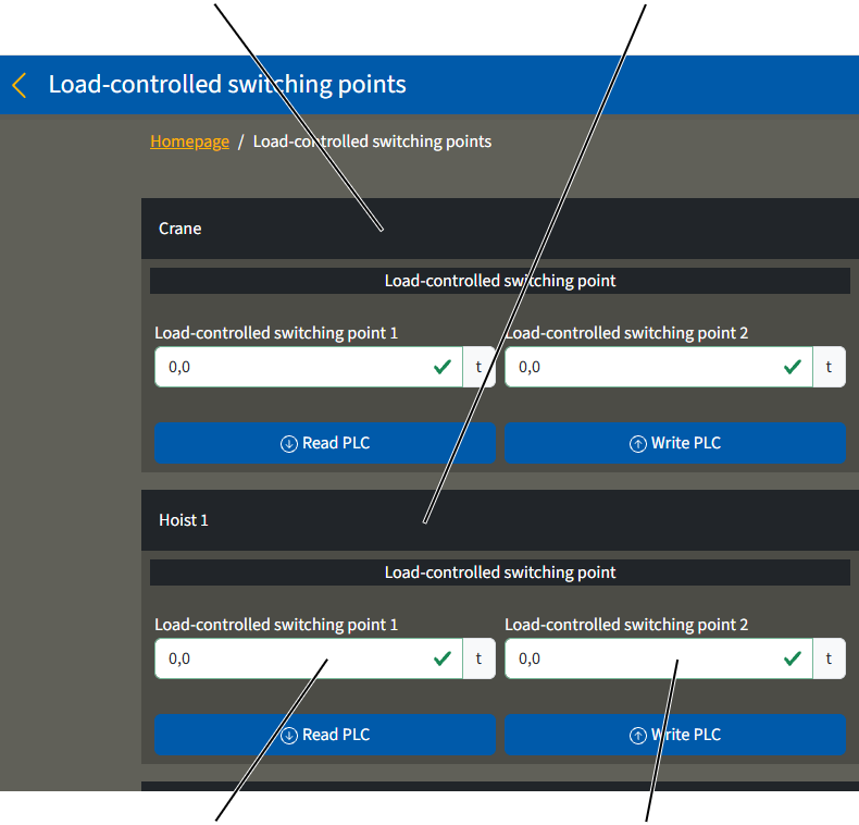
- The window "Load-controlled switching points" appears.
- The current settings are displayed.
- Enter the load as of which the corresponding output should be switched.
- The load can be entered separately for the crane (total load of both hoists) and for the individual hoist(s).
- There are up to two switching points available, which can switch at different loads.
- Additional functions of the load-controlled switching points and the electrical connection can be found in the wiring diagram.
- Click on the "Write PLC" button.
The function of the load-controlled switching points is monitored by the PLC. Every output of each individual load-controlled switching point has an additional input for this. As soon as an output has switched, a signal must be present on the respective corresponding input. If this signal is not present, an error message is displayed. The electrical connection is done according to the specific order and is specified in the wiring diagram.
Setting slack rope detection
The slack rope detection prevents the wire rope from being unwound further when setting down the load or the bottom block. Lowering is halted when the measured load on the load hook falls below a set value. Without slack-rope detection, the wire rope could continue to be unwound from the cable drum and would hang loosely and remain so, and when being wound again onto the cable drum it might not have the proper position and pretension.
A load lifting attachment (e.g. crosshead) can be taken into account for the load measured on the load hook by subtracting its weight from the measured load. The minimum load can be set in KranOS. If the load display was set to zero with the "Tare" function, this is not however taken into account for the slack-rope detection.
For this work step, access from a laptop or tablet computer to KranOS is necessary. The user "Service" (user level [2]) must be logged in.
Setting slack rope detection
Overview: Navigation in KranOS |
|---|
User "SERVICE" 🡪 "Load-controlled switching point" |
- Log in to KranOS with user "Service" (user level [2]). See "Logging into and registering in KranOS".
- In the start window: Click on the "Load-controlled switching point" menu item in the "Settings" menu (three horizontal bars).
Setting slack rope detection
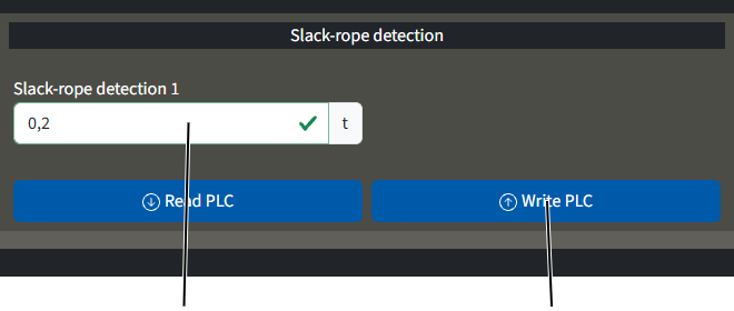
- The window "Load-controlled switching points" appears.
- The current settings are displayed.
- Enter a minimum load as of which the lowering should be halted.
The weight of a load lifting attachment, for example, can be entered for this.
- Click on the "Write PLC" button.
Setting advanced travel profile parameters (crane travel profile, trolley travel profile)
The travel profiles of the drive axles (crane travel profile, trolley travel profile) can be adjusted to individual usage in the acceleration and braking time as well in the maximum and minimum speed.
For this work step, access from a laptop or tablet computer to KranOS is necessary. The user "Service" (user level [2]) must be logged in.
Calling up parameters for travel profile
Overview: Navigation in KranOS |
|---|
User "SERVICE" 🡪 "Crane travel" 🡪 "Crane travel profile parameter" |
User "SERVICE" 🡪 "Trolley travel" 🡪 ׅ"Trolley travel profile" |
- Log in to KranOS with user "Service" (user level [2]). See "Logging into and registering in KranOS".
- Select the desired crane axis (e.g. crane travel) in the main menu.
- The window for the requested crane axis appears.
- Click on the "Crane travel profile parameter" (or "Trolley travel profile parameter") menu item in the "Settings" menu (three horizontal bars).
Setting parameters for travel profile
- The "Parameter" window for the corresponding crane axis appears.
- The current values are displayed.
- Set the desired values.
SpeedSetting acceleration time and braking time
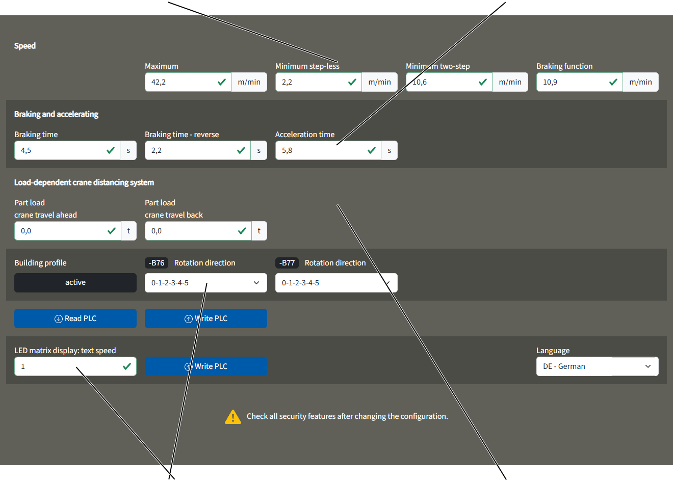
"Speed" section:
This section pertains to the maximum and minimum travel speed of the crane (or trolley) in connection with the various movement profiles.
The crane (or trolley) travels slower at a low value and faster at a high value.
The movement profiles can be selected on the "Movement profile" page. See "Selecting movement profiles".
"Maximum": Maximum crane (or trolley) travel speed.
With step-less movement profile: If the button is pressed and held in the second level, the crane (or trolley) accelerates to this maximum travel speed.
With two-step movement profile: If the button is pressed and held in the second level, the crane (or trolley) accelerates to this travel speed.
- "Minimum step-less": This is the lowest speed at which the crane (or trolley) can travel with a step-less movement profile.
If the button is pressed and held in the first level, the crane (or trolley) accelerates to this travel speed.
- "Minimum two-step": This is the lowest speed at which the crane (or trolley) can travel with a two-step movement profile.
If the button is pressed and held in the first level, the crane (or trolley) accelerates to this travel speed.
- "Braking function": Travel speed at which the crane (or trolley) brakes if the travel limit switch for the braking function is activated.
"Braking and accelerating" section:
This section pertains to the braking time and the acceleration time of the crane (or trolley) in connection with the various movement profiles.
The drive brakes or accelerates faster at a low value and slower at a high value.
The movement profiles can be set on the "Movement profile" page. See “Selecting movement profiles”.
- "Braking time": Time in which the drive brakes from the travel speed.
The entered time always refers to the complete braking from the maximum travel speed according to the type plate until a standstill is reached.
With this value, the drive brakes when the key is released from the first or second level.
- "Braking time - reverse": Time in which the drive brakes from the travel speed for reversing.
The entered time always refers to the complete braking from the maximum travel speed according to the type plate until a standstill is reached.
With this value, the drive brakes when the key is released from the first or second level and the key for the opposite direction is directly pressed and held.
- "Acceleration time": Time in which the drive accelerates to the travel speed.
The entered time always refers to the complete acceleration from a standstill until the maximum travel speed according to the type plate is reached.
With this value, the drive accelerates from a standstill when the key is pressed in the first level, or if the key is pressed and held in the second level.
Additional sections:
- Only with crane travel profile: "Part load crane travel ahead" and "Part load crane travel back": Load as of which the load-dependent crane distancing system is to be switched on. See "Display status of crane axes". The load can be separately set for both travel directions.
With a general (load independent) crane distancing system, the value that is entered here is irrelevant.
- "Building profile": This displays whether a building profile is available for the crane.
- "LED matrix display: text speed": Speed with which the scrolling text runs through the LED matrix display. For a lower value, the scrolling text runs faster; for a higher value it runs more slowly.
The set text speed is saved directly in the LED matrix display and not in the PLC. For this reason, the "Write PLC" button next to the input field must be clicked separately. Also, the current value which is saved in the LED matrix display is not displayed here.
The language for the LED matrix display can be selected via the "Language" drop-down menu.
- "Rotation direction" for –B76 and –B77 (for crane travel) or –B56 and –B57 (for trolley travel): Rotation direction for both cross-type limit switches that are used for the building profile control. The numbers from 0 to 5 indicate the switching statuses of the cross-type limit switch. They can be read at a small arrow on the cross-type limit switch.
If the cross-type limit switch is installed correctly (installed according to layout plan, housing below, switching cross above) it interconnects the switching statuses in descending order by (5‑4‑3‑2‑1‑0), if the crane travels forwards or the trolley travels to the right.
If the cross-type limit switch is installed upside down (installed according to layout plan, housing above, switching cross below) it interconnects the switching statuses in ascending order by (0‑1‑2‑3‑4‑5), if the crane travels forwards or the trolley travels to the right.
Setting advanced parameters for hoist profile
The hoist profile can be adjusted to individual usage in the acceleration and braking time as well in the maximum and minimum speed.
For this work step, access from a laptop or tablet computer to KranOS is necessary. The user "Service" (user level [2]) must be logged in.
Calling up parameters for the hoist profile
Overview: Navigation in KranOS |
|---|
User "SERVICE" 🡪 "Hoist" 🡪 "Hoist profile parameter" |
- Log in to KranOS with user "Service" (user level [2]). See "Logging into and registering in KranOS".
- Select the desired hoist (e.g. hoist 1) in the main menu.
- The window for the requested hoist appears.
- Click on "Hoist profile parameter" in the "Settings" menu (three horizontal bars).
Setting parameters for hoist profile
- The "Parameter" window for the corresponding crane axis appears.
- The current values are displayed.
- Set the desired values.
"Speed" section
"Braking and accelerating" section"Speed super precision lifting" and "Braking and accelerating in super
precision lifting" sections
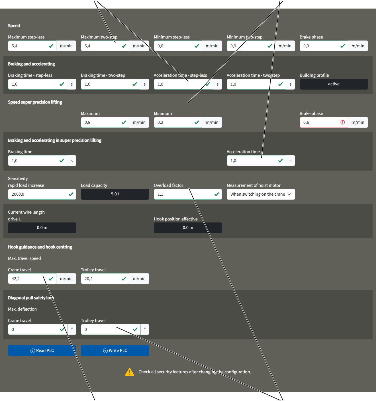
"Anti-tilt device" section
"Speed" section:
This section pertains to the maximum and minimum lifting speed of the hoist in connection with the various movement profiles.
The hoist lifts/lowers slower at a low value and faster at a high value.
The movement profiles can be selected on the "Movement profile" page. See “Selecting movement profiles”.
- "Maximum step-less": The maximum lifting speed with a step-less movement profile.
If the button is pressed and held in the second level, the hoist accelerates maximally to this lifting speed.
With double lifting speed (optional): If the hoist can lift and lower with double lifting speed, the value in this input field also applies for the maximum possible additional lifting speed (above 100% of the lifting speed according to the type plate). The lifting speed is specified on the type plate of the hoist motor and in the technical data, and can therefore be increased up to double. The actual maximum possible additional lifting speed (over 100%) depends on the attached load and is automatically reduced according to the attached load.
- "Maximum two-step": The maximum lifting speed with a two-step movement profile.
If the button is pressed and held in the second level, the hoist accelerates to this lifting speed.
With double lifting speed (optional): If the hoist can lift and lower with double lifting speed, the value in this input field also applies for the maximum possible additional lifting speed (above 100% of the lifting speed according to the type plate). The lifting speed is specified on the type plate of the hoist motor and in the technical data, and can therefore be increased up to double. The actual maximum possible additional lifting speed (over 100%) depends on the attached load and is automatically reduced according to the attached load.
- "Minimum step-less": The slowest lifting speed with a step-less movement profile.
If the button is pressed and held in the first level, the hoist accelerates to this lifting speed.
- "Minimum two-step": The slowest lifting speed with a two-step movement profile.
If the button is pressed and held in the first level, the hoist accelerates to this lifting speed.
- "Brake phase": Lifting speed at which the hoist brakes in the brake phase immediately before the hoist limit switch is activated.
"Braking and accelerating" section:
This section pertains to the braking time and the acceleration time of the hoist in connection with the various movement profiles.
The hoist drive brakes or accelerates faster at a low value and slower at a high value.
The movement profiles can be selected on the "Movement profile" page. See “Selecting movement profiles”.
- "Braking time - step-less": Time in which the hoist drive brakes with a step-less movement profile.
The entered time always refers to the complete braking from the maximum lifting speed according to the type plate until a standstill is reached.
With this value, the hoist continues braking when the key is released from the first or second level until the key is then switched back in the first level.
With double lifting speed (optional): The value specified refers to the lifting speed according to the type plate. With double lifting speed, the braking time is also doubled in real crane operation depending on the load.
- "Braking time - two-step": Time in which the hoist drive brakes with a two-step movement profile.
The entered time always refers to the complete braking from the maximum lifting speed according to the type plate until a standstill is reached.
With this value, the hoist brakes when the key is released from the first or second level.
With double lifting speed (optional): The value specified refers to the lifting speed according to the type plate. With double lifting speed, the braking time is also doubled in real crane operation depending on the load.
Entering a very small value enables a very spontaneous braking behaviour which, even for hoists with frequency converters, approaches the braking behaviour of hoists with contactor control.
- "Acceleration time - step-less": Time in which the hoist drive accelerates with a step-less movement profile.
The entered time always refers to the complete acceleration from a standstill until the maximum lifting speed according to the type plate is reached.
With this value, the hoist accelerates from a standstill when the key is pressed in the first level, or if the key is pressed and held in the second level.
With double lifting speed (optional): The value specified refers to the lifting speed according to the type plate. With double lifting speed, the acceleration time is also doubled in real crane operation depending on the load.
- "Acceleration time - two-step": Time in which the hoist drive accelerates with a two-step movement profile.
The entered time always refers to the complete acceleration from a standstill until the maximum lifting speed according to the type plate is reached.
With this value, the hoist accelerates from a standstill when the key is pressed in the first level, or if the key is pressed and held in the second level.
With double lifting speed (optional): The value specified refers to the lifting speed according to the type plate. With double lifting speed, the braking time is also doubled in real crane operation depending on the load.
Entering a very small value enables a very spontaneous braking behaviour which, even for hoists with frequency converters, approaches the acceleration behaviour of hoists with contactor control.
"Speed super precision lifting" and "Braking and accelerating in super precision lifting" sections:
These sections refer to the maximum and minimum lifting speed of the hoist as well as the braking time and acceleration time in connection with the super-precision lifting function.
With the super-precision lifting option, the hoist can be switched to an especially slow lifting speed. This enables extremely exact positioning of the load.
With activated super-precision lifting in pole-switchable hoist drives, the frequency converter is switched from winding with fast lifting speed to winding with slow lifting speed.
For single-winding hoist drives that are not pole-switchable, (e.g. GM7000.2), the speed of the hoist motor is monitored by the frequency converter using a separate absolute rotary encoder, thus also enabling full torque at very slow lifting speeds so that the load can be held until a standstill is reached even without braking.
The settings in this section refer to the technology actually used on the crane, including super-precision lifting for pole-switchable hoist drives as well as on hoist drives that are not pole-switchable.
Super-precision lifting can be switched on and off at the transmitter or the pendant control.
The values entered in these sections (braking time, maximum speed, minimum speed, acceleration time, brake phase speed) apply when super-precision lifting is switched on on the transmitter or on the pendant control.
The meaning of the values is identical for the sections "Speed" and "Braking and accelerating".
Additional sections:
- "Sensitivity rapid load increase": Sensitivity with which the lifting of a load with a sudden jolt is registered. The displayed number is a threshold value that is dependent on time and measured load. The smaller the number, the more sensitively ABUControl reacts to a rapid load increase. The measuring of the rapid load increase always occurs 50 ms after pressing the lift button. If a rapid load increase is registered, the hoist brakes to slow lifting speed, maintains the slow lifting speed for 2 seconds and then accelerates again if the key continues to be held pressed at the second level.
- "Load capacity": Maximum load capacity of the hoist.
- "Overload factor" Factor (multiple) of the maximum load capacity at which the overload protection is activated.
- "Measurement of hoist motor": Here you set whether or not the hoist motor will be electrically measured upon switching on the crane. During measuring, certain electrical values of the hoist motor are checked with a test current, compared with the measurement results from the initial start-up of the crane at the commissioning, and the frequency converter is set accordingly. In this way, the frequency converter can take into account the thermal state of the hoist motor during running operation. Normally, measurement upon switching on the crane is activated. With older frequency converters (ATV32), the measurement may need to be deactivated and the frequency converter reparameterized.
- "Current wire length Drive 1": Length of the entire wire rope that currently has been unrolled from the cable drum to the fixed point.
With twin hoist: The "Current wire length drive 2" is also displayed. The displayed value is then the respective length of wire rope that currently has been unrolled from the cable drum up to the compensating sheave (middle deflection roller above on the wire rope hoist or on the bottom block).
- "Hook position effective": Hook position (measure distance from centre of cable drum to centre of deflection roller of bottom block) based on the wire length. The reeving and also both cable drums on twin hoists are taken into consideration here.
Only for hoist with contactor control
The sections "Speed", "Braking and accelerating", "Speed super precision lifting", "Braking and accelerating in super precision lifting" as well as the selection field "Measurement of hoist motor" are displayed in KranOS, however, the entered values are not evaluated.
For a hoist with contactor control, the slow and fast winding of the hoist motor is switched via contactors. Speed, braking time and acceleration time are determined by the physical properties of the hoist motor and not regulated by the frequency converter.
"Hook guidance and hook centring" section:
- "Max. travel speed": This setting determines the maximum travel speed for the crane and trolley when hook guidance and hook centring are active.
"Anti-tilt device" section:
- "Max. deflection": This setting determines the maximum deflection (in degrees) of the rope during crane and trolley travel. If this value is exceeded, either the entire crane or just the hoisting movement will stop.
The anti-tilt device is only available if the crane is fitted with an inclinometer and the calibration has been completed (see "Calibrating the inclinometer").
Activating and deactivating sway control
The length of the lifting tackle must be correctly set so that the sway control functions correctly.
Both the switching on and off as well as the sway control setting can be quickly and conveniently carried out via the ABURemote transmitter. See "ABURemote" product manual.
Alternatively, the sway control can also be switched on and off and set in KranOS. If the sway control is switched on in KranOS, it must be switched off there as well. The setting in KranOS is independent of the ABURemote transmitter and is not displayed there.
For this work step, access from a laptop or tablet computer to KranOS is necessary. The user "Service" (user level [2]) must be logged in.
Opening sway control
Overview: Navigation in KranOS |
|---|
User "SERVICE" 🡪 "Hoist" 🡪 "Hoist profile parameter" 🡪 "Sway control parameter" |
- Log in to KranOS with user "Service" (user level [2]). See "Logging into and registering in KranOS".
- Select the desired hoist (e.g. hoist 1) in the main menu.
- The window for the requested hoist appears.
- Click on the "Hoist profile parameter" menu item in the "Settings" menu (three horizontal bars).
- The "Hoist profile parameter" window appears.
- Click on the "Sway control parameter" menu item in the "Settings" menu (three horizontal bars).
Setting and activating sway control
"Lifting tackle" input field
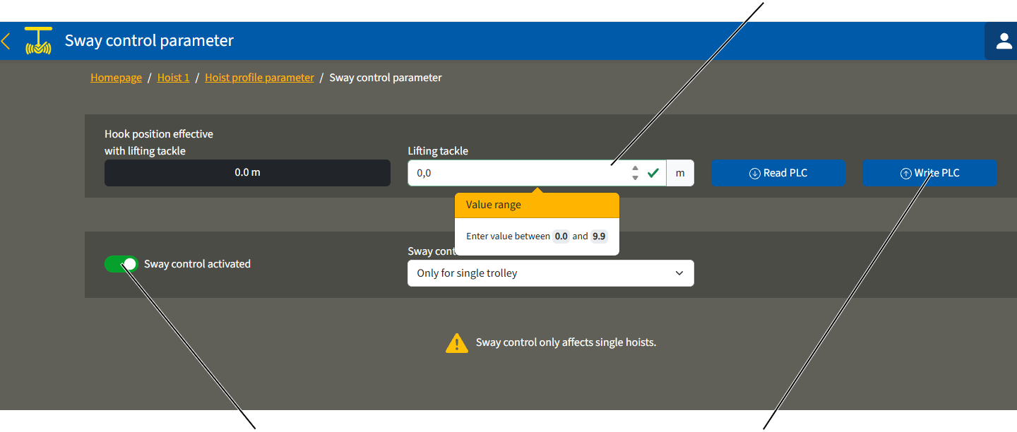
- The "Sway control parameter" window appears.
Input the length of the lifting tackle:
- Enter the distance between the load hook and the centre of gravity in the "Lifting tackle" input field. This factors in the length of the lifting tackle.
See also the "ABUS radio remote control" product manual.
- Click on the "Write PLC" button.
Switch sway control on:
- Click on the "Sway control" button.
- The button's background turns green.
- The sway control is now activated.
Switch sway control off:
- Click on the "Sway control" button.
- The button's background is no longer green.
- The sway control is now deactivated.
Enabling sway control for multiple trolleys
The sway control initially functions only with a single hoist or on a crane with several trolleys in individual control, providing the unused trolley is in the parking position (load hook triggers top hoist limiter).
During the joint operation of several trolleys or in tandem operation, the sway control must be separately enabled.
For this work step, access from a laptop or tablet computer to KranOS is necessary. The user "Service" (user level [2]) must be logged in.
Opening sway control
Overview: Navigation in KranOS |
|---|
User "SERVICE" 🡪 "Hoist" 🡪 "Hoist profile parameter" 🡪 "Sway control parameter" |
- Log in to KranOS with user "Service" (user level [2]). See "Logging into and registering in KranOS".
- Select the desired hoist (e.g. hoist 1) in the main menu.
- The window for the requested hoist appears.
- Click on the "Hoist profile parameter" menu item in the "Settings" menu (three horizontal bars).
- The "Hoist profile parameter" window appears.
- Click on the "Sway control parameter" menu item in the "Settings" menu (three horizontal bars).
Enabling sway control for a single trolley or for multiple trolleys
"Sway control available" drop-down menu
- The "Sway control parameter" window appears.
- Enabling sway control:
- "Only for single trolley": The sway control can only be activated for a single hoist or for a crane with several trolleys in individual control, providing the unused trolley is in parking position (top hoist limiter has been contacted by the load hook).
- "Single and multiple trolleys (joint operation)": The sway control can be activated for a single hoist, for a crane with several trolleys in individual control or in joint operation, and for two cranes in tandem operation.
Instructions for sway control for multiple trolleys:
The calculation of the sway control only functions correctly in joint operation of multiple trolleys or in tandem operation if the crane operator observes these conditions:
- Crane and trolley must be the same type and size.
- The load must be slung correctly:
Hook position
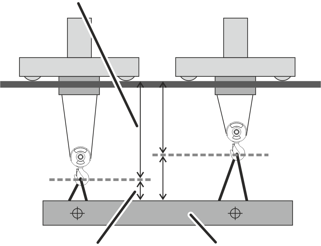
Hook position
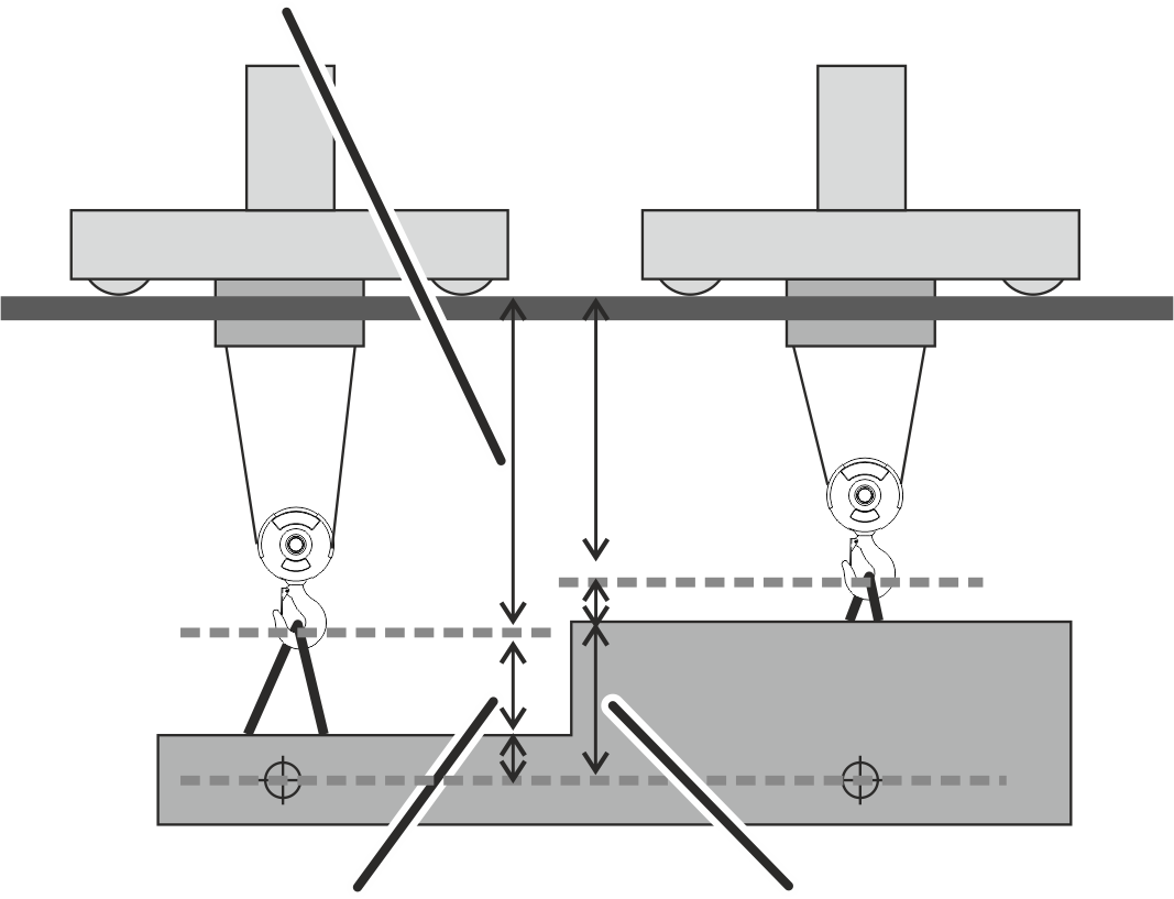
- The length of the lifting tackle must be entered:
In joint operation of multiple trolleys, the length of the lifting tackle for trolley 1 must be entered.
In tandem operation, the length of the lifting tackle from the first crane must be entered. The first crane has the IP address 192.168.1.1
Setting hook assistants (hook guidance and hook centring)
The hook guidance allows the load hook to be moved by hand. Both the crane and the trolley travel in the direction the load hook is moved or pulled.
The "Hook centring" function automatically positions the load hook vertically above the load when the load is being "lifted". This prevent diagonal pull on the load.
An inclinometer on the fixed point crosshead or the trolley frame measures the wire rope deflection.
Note:
Hook centring is an assistance function. The crane driver is still responsible. The crane driver should generally make sure that the load is not lifted with diagonal pull.
Overview: Navigation in KranOS |
|---|
User "SERVICE" 🡪 "Movement profile" |
- Log in to KranOS with user "Service" (user level [2]). See "Logging into and registering in KranOS".
- Click on the "Movement profile" menu item in the "Settings" menu (three horizontal bars).
- The "Movement profile" window appears.
Activate/deactivate hook guidance/hook centring
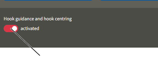
- Activate or deactivate the function with the "Hook guidance and hook centring" button.
- The button's background turns red.
"Activate/deactivate hook guidance and hook centring" buttonSensitivity of hook guidance and hook centring
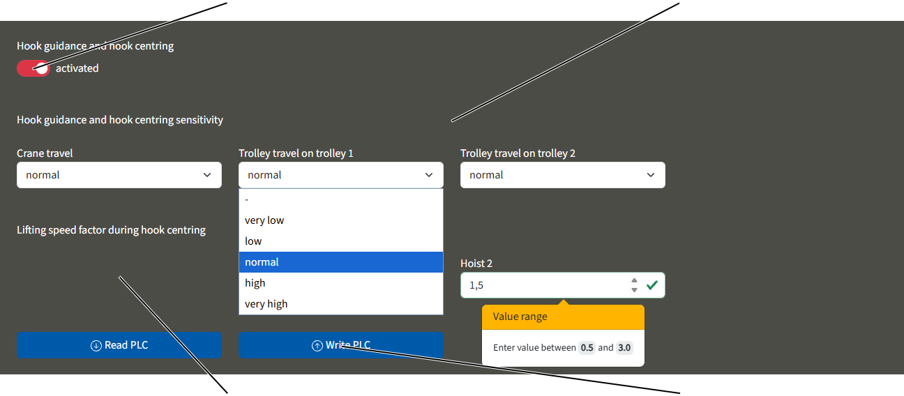
Setting the sensitivity
- Use the relevant drop-down menu to set the sensitivity of the hook assistants for crane travel and trolley travel.
- Click on the "write PLC" button and make sure that the parameters are accepted in KranOS:
Setting the lifting speed factor
The lifting speed parameter can be used to set how quickly the hoist raises the load when hook centring is active. The value entered must be between 0.5 and 3.0.
- Click in the input field for the "lifting speed factor with hook centring" for the relevant hoist.
- Enter the desired value.
The value 1 corresponds exactly to the lifting speed during the braking phase. For values below 1, the lifting speed is slower than the set braking phase. For values above 1, the lifting speed is faster than the braking phase. See also "Setting advanced parameters for hoist profile".
- Click on the "Write PLC" button.
- The value is saved.
Note:
If the factor is set too high, there is a risk that the load will be lifted before the trolley is centred over it. This would cause the load to swing.
Adjusting positioning control points
In KranOS, individual points of the positioning control that were previously programmed using ABURemote in teach-in mode can be adjusted retrospectively. See the ABURemote product manual, "Positioning control with ABUControl: Teaching individual points". Subsequent adjustment is possible for the LIN linear positioning control and the manual positioning control. This is not possible for the PTP point-to-point positioning control, as the points within the route cannot be adjusted.
A total of 127 positions can be created for the LIN linear positioning control and the manual positioning control.
For this work step, access from a laptop or tablet computer to KranOS is necessary. The user "Service" (user level [2]) must be logged in.
Calculating the crane track length:
In order to create positions for the positioning control system, the length of the crane track must be known. If this is not known, the crane track length can be calculated in KranOS.
The length of the crane track must also be calculated if it exceeds 262 metres.
Overview: Navigation in KranOS |
|---|
User "SERVICE" 🡪 "Positioning control" |
- Log in to KranOS with user "Service" (user level [2]). See "Logging into and registering in KranOS".
- In the start window: Click on the "Positioning control" menu item in the "Settings" menu (three horizontal bars).
- The "Positioning control" window appears
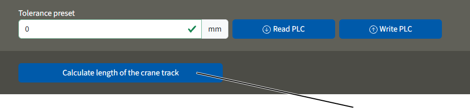
- Move the crane to centre of the building if possible.
- Click on the "Calculate length of crane track" button.
- The length of the crane track is calculated and saved.
For distance sensors: the measured values from the distance sensors in both directions along the crane track are added together.
For absolute position measurement systems: the absolute position of the crane along the measuring system is stored.
Where there are several overlapping absolute position measuring systems: The crane's absolute position is recorded and the overlapping range of the two absolute position measuring systems is subtracted.
Setting the tolerance
The positioning control's tolerance for individual positions can be set in KranOS. This determines how far the load hook is permitted to deviate from the programmed positions when moving into position. When a new position is created, KranOS automatically applies the previously set default value.
Overview: Navigation in KranOS |
|---|
User "SERVICE" 🡪 "Positioning control" |
"Tolerance default" field"Write PLC" button
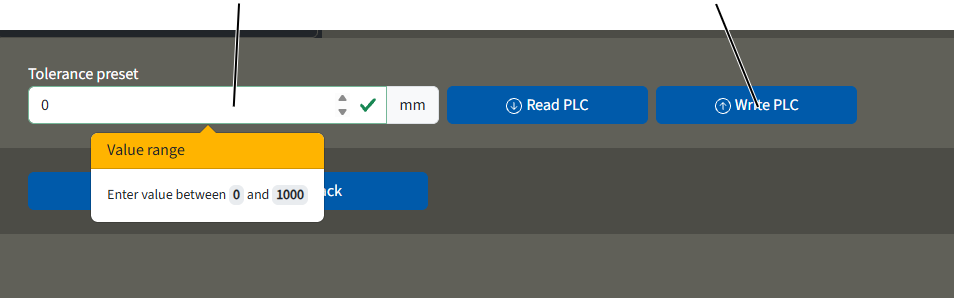
- Log in to KranOS with user "Service" (user level [2]). See "Logging into and registering in KranOS".
- In the start window: Click on the "Positioning control" menu item in the "Settings" menu (three horizontal bars).
- Enter the desired value in the "Tolerance default" field.
The specified tolerance should be at least 10 mm. If the tolerance were any smaller, the crane would move too precisely to the position and would immediately overshoot the set point, which could cause the crane to jerk at that position.
Create/edit position
"Saved positions of positioning control" input field"Teaching-in position" button
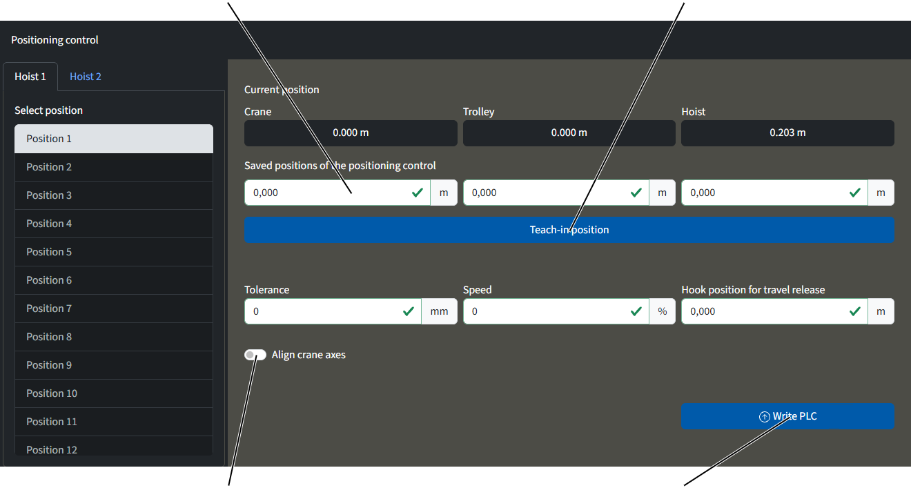
- Select hoist and position.
- The input fields for the selected hoist are highlighted in white. Values can only be adjusted in these fields.
- Create or adjust position values.
Or:
Click on "Teaching-in position" button.
- The current values of the positions of the crane, trolley and hoist are adopted in the display.
Any values changed are identified with an orange frame.
- Click on the "Write PLC" button.
- The values are saved.
Note:
Entering a value for "Speed" will change all speeds – including the travel and braking speeds for crane and trolley travel, as well as the lifting and lowering speeds of the hoist during positioning!
Creating points of the building profile control
When controlling the building profile via the crane position, individual points on the obstacles can be created or adjusted in KranOS. This is not possible when controlling the building profile using cross-type limit switches. In that case, the obstacles can only be adjusted by ABUS. See "ABUS Service".
For this work step, access from a laptop or tablet computer to KranOS is necessary. The user "Service" (user level [2]) must be logged in.
Overview: Navigation in KranOS |
|---|
User "SERVICE" 🡪 "Movement profile" 🡪 "Building profile (via crane position)" |
- Log in to KranOS with user "Service" (user level [2]). See "Logging into and registering in KranOS".
- In the start window: Click on the "Movement profile" menu item in the "Settings" menu (three horizontal bars).
- In the movement profile: Click on the "Building profile (via crane position)" menu item in the "Settings" menu (three horizontal bars).
Creating a new obstacle
An obstacle is represented as a cuboid with two corner points. One corner point is at the bottom/front/left, the other is at the top/back/right.
If an obstacle is more complex, it can be made up of several cuboids, each of which is positioned over the two stated corner points. It is important to note that the cuboids will overlap, as the measuring systems have a certain margin of error.
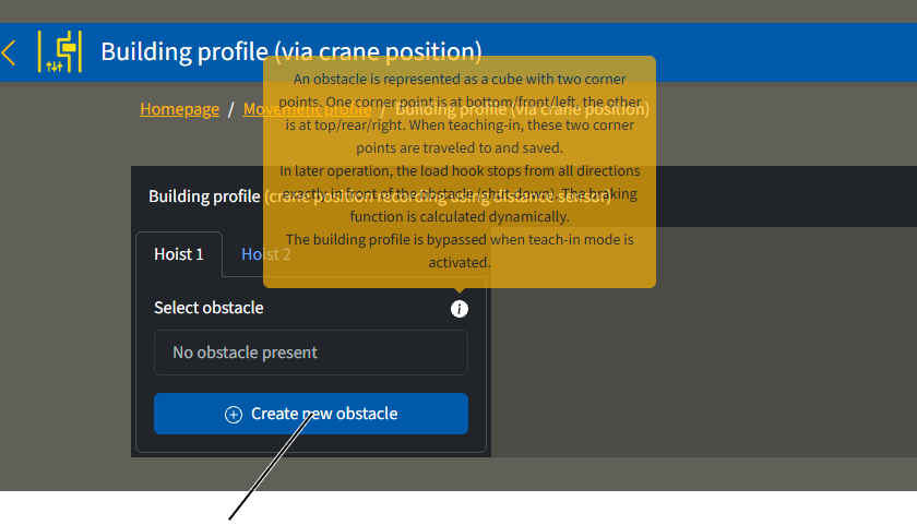
- Click on the "Create new obstacle" button.
- On the right, you will see an overview of your current position and the input fields for the obstacle.
Save bottom/front/left corner:
Current position"Accept current position" button
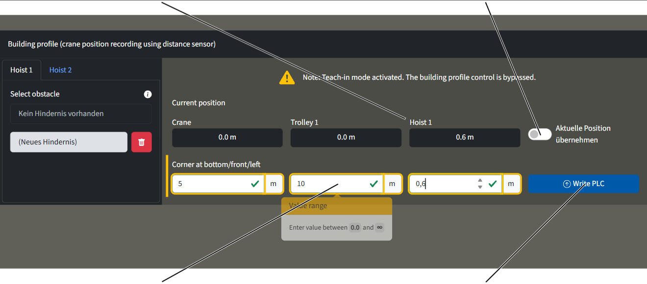
- Either click on the "Accept current position" button.
Or
Enter the values for the corner bottom/front/left in the input fields.
- Click on the "Write PLC" button.
- The bottom-left corner has been saved and the input fields for the top-right corner are now displayed.
Save top/back/right corner:
Cancel create obstacle
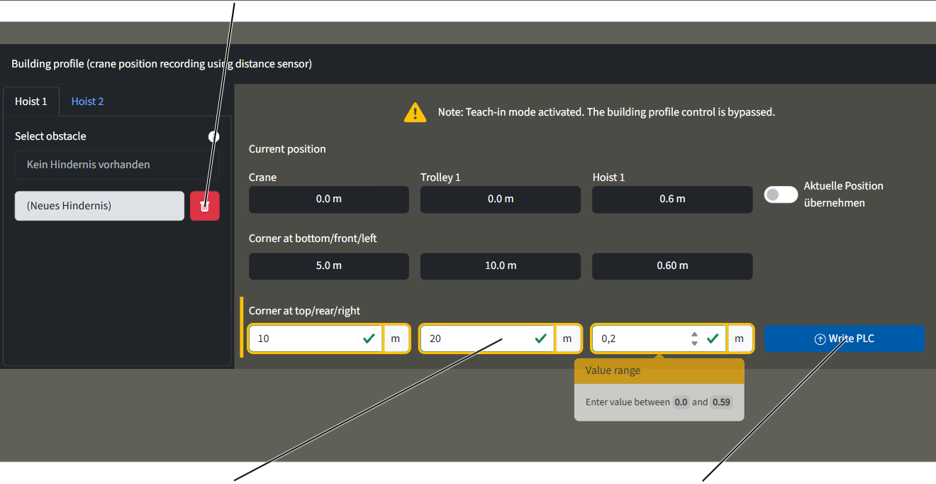
- Either click the "Apply current position" button.
Or
Enter the values for the corner top/back/right input fields.
- Click on the "Write PLC" button.
- The obstacle is saved and is shown on the left in the column.
Note:
The obstacle is only saved and created once the crane has been restarted.
Copy, adjust or delete obstacle
To copy, edit or delete an obstacle, you must first create one. See "Creating points of the building profile control".
- Select hoist.
- Select obstacle.
- The obstacle values are displayed.
"Copy obstacle" button"Delete obstacle" button
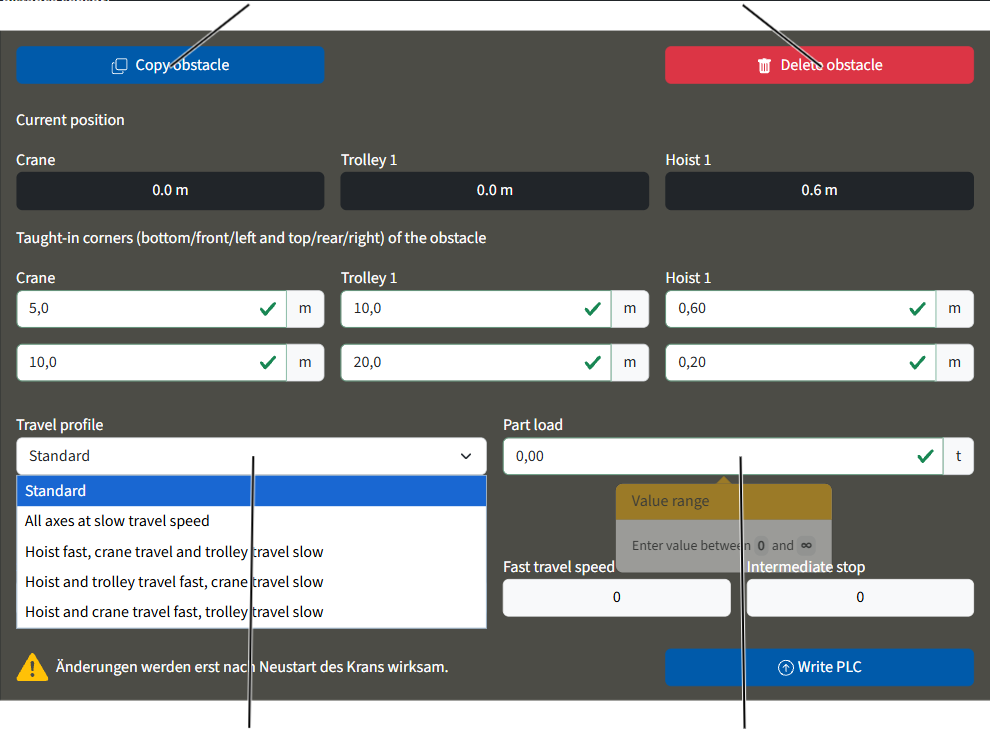
Copy obstacle:
- Click on the "Copy obstacle" button.
- Adjust obstacle if necessary.
Delete obstacle:
- Click on the "Delete obstacle" button.
- The obstacle is deleted.
- The obstacle will be removed immediately when you click the button!
Adjust obstacle:
- Adjust the values of the teached-in corner.
- Select the travel profile in the drop-down menu if necessary.
- Enter the part load, if necessary.
Bridge obstacle selection
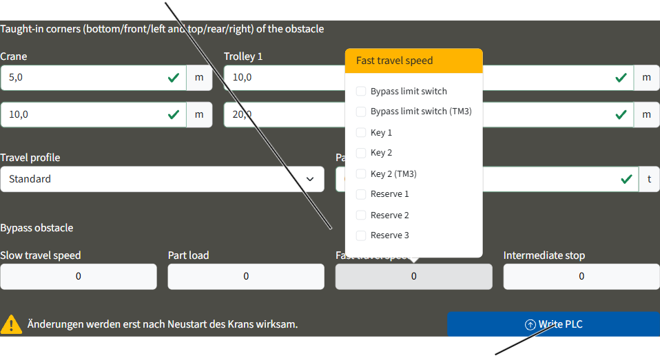
- If you need to bypass an obstacle: Click the relevant selection field and select the participant to be bypassed.
- Click on the "Write PLC" button.
- The obstacle is adjusted.
Setting the tolerance for the building profile control
The tolerance of the building profile control with regard to the corner points of obstacles can be entered separately for each obstacle. When a new obstacle is created, KranOS automatically applies the previously set default value.
Overview: Navigation in KranOS |
|---|
User "SERVICE" 🡪 "Movement profile" 🡪 "Building profile (via crane position)" |
- Log in to KranOS with user "Service" (user level [2]). See "Logging into and registering in KranOS".
- In the start window: Click on the "Movement profile" menu item in the "Settings" menu (three horizontal bars).
- In the movement profile: Click on the "Building profile (via crane position) menu item in the "Settings" menu (three horizontal bars).
Setting the load-dependent crane distancing system
With the load-dependent crane distancing system, the crane brakes and stops as soon as a set distance to another crane on the same run is fallen short of and a load above a set value is simultaneously moved.
- Read the switching statuses of the crane distancing system: See "Display status of crane axes".
- Display the switching status of the receiver of the signal transmission from another crane on the same run: See "Display status of crane axes".
- Set the load as of which the load-dependent crane distancing system is to be switched on: See "Setting advanced travel profile parameters (crane travel profile, trolley travel profile)".
Display additional PLC diagnosis
The additional PLC in ABUControl can be used to implement customised special functions or special functions that are not part of ABUControl. These are developed, programmed and made available by ABUS on a project-specific basis. The software for these special functions runs independently within the additional PLC of ABUControl and is connected to ABUControl via a standardised interface.
Special functions can be used, for example, to control complex load-handling devices, obstacle detection systems or release signals from third-party systems.
This page in KranOS shows which crane axis (crane travel, trolley travel, lifting/lowering) is currently enabled by the special function of the additional PLC, and at what speed. This allows you to check what influence the additional PLC is currently having on the crane's regular functions, or whether it is currently disabling or restricting them.
Overview: Navigation in KranOS |
|---|
User "SERVICE" 🡪 "PLC diagnosis" 🡪 "Additional PLC diagnosis" |
- Log in to KranOS with user "Service" (user level [2]). See "Logging into and registering in KranOS".
- In the start window: Click on the "PLC diagnosis" menu item in the "Settings" menu (three horizontal bars).
- In the movement profile: Click on the "Additional PLC diagnosis" menu item in the "Settings" menu (three horizontal bars).
Read out additional PLC release signals
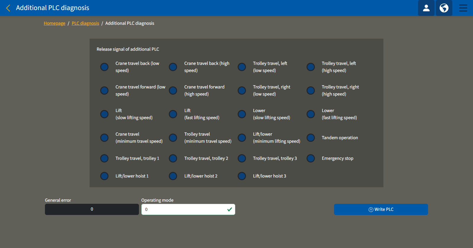
Meaning of colours:
- Blue: Authorisation has not been granted by the additional PLC. The relevant function is therefore disabled in ABUControl.
- Green: Authorisation has been granted by the additional PLC. The relevant function is therefore enabled in ABUControl and can be used.
Function areas:
- "Crane travel forwards/backwards at minimum, slow and fast speeds": Depending on the programme sequence, the additional PLC can either enable or disable crane travel at the relevant speed. Once the release signal is given, the crane can be moved in the corresponding direction.
- "Trolley travel left/right at minimum, slow and fast speeds": Depending on the programme sequence, the additional PLC can either enable or disable trolley travel at the respective speed. Once the release signal is given, the trolley can be moved in the corresponding direction. This applies to the currently selected trolley.
- "Lifting/lowering at minimum, slow and fast lifting speeds": Depending on the programme sequence, the additional PLC can either enable or disable the lifting movement at the respective speed. Once the release signal is given, the hoist can lift or lower. This applies to the currently selected trolley.
- "Trolley travel: trolley 1, 2 or 3": Depending on the program sequence, the additional PLC can either enable or disable the trolley travel for the specified trolley. If the release signal is given, the specified trolley can be moved. This applies to the specified trolley, regardless of which trolley is currently selected.
- "Lift/lower hoist 1, 2 or 3": Depending on the program sequence, the additional PLC can either enable or disable the specified hoist. Once the release signal is given, the specified hoist can be lifted or lowered. This applies to the specified hoist regardless of the currently selected trolley.
- "Emergency stop": Depending on the program sequence, the additional PLC can either disable or enable the emergency stop. Once the release signal is given, the crane can be operated. If the emergency stop is disabled by the additional PLC, this applies to the entire crane.
- "Tandem operation": Depending on the program sequence, the additional PLC can either disable or enable tandem operation. If the release signal is given, tandem operation can be used on the crane as required. If tandem operation is disabled by the additional PLC, it cannot be activated.
Using error and operating modes of the additional PLC
- "General error": This displays an error code from the additional PLC. The meaning of the specific error code depends on the program flow of the additional PLC. The error codes are described in the documentation for the customer-specific special function.
- "Operating mode": The number specified here allows an operating mode to be set and passed on to the additional PLC. The meaning of the respective operating mode depends on the program sequence of the additional PLC. The operating modes are described in the documentation for the customer-specific special function.
Entering the start value for the load population recorder
When exchanging a faulty PLC, the full-load hours of operation must be read out from the load population recorder, and after installation of the new PLC then entered as the new start value of the load population recorder.
For this work step, access from a laptop or tablet computer to KranOS is necessary. The user "Service" (user level [2]) must be logged in.
Calling up the load population recorder
Overview: Navigation in KranOS |
|---|
User "SERVICE" 🡪 "Hoist" 🡪 "Hoist calibration" |
- Log in to KranOS with user "Service" (user level [2]). See "Logging into and registering in KranOS".
- Select the desired hoist (e.g. hoist 1) in the main menu.
- The window for the requested hoist appears.
- Click on the "Hoist calibration" menu item in the "Settings" menu (gear wheel on yellow background).
Reading the load population recorder

- The "Hoist calibration" window appears.
- Note the value in the "Consumed value" description field in the "Load population recorder" line.
Transferring the load population recorder
In the new PLC:

- In the "Load population recorder" line, enter the previously noted value in the "Start value" input field.
- Click on the "Write PLC" button.
Displaying PLC diagnosis with version information
Version information from the KranOS window "PLC diagnosis" can be helpful for analysing faults or in conversation with ABUS Service.
For this work step, access from a laptop or tablet computer to KranOS is necessary. The user "CUSTOMER" (user level ‚[1]) or "SERVICE" (user level [2]) must be logged in.
Displaying program version of ABUControl
Overview: Navigation in KranOS |
|---|
User "CUSTOMER" or "SERVICE" 🡪 "PLC diagnosis" 🡪 "PLC SD card" |
- Log in to KranOS with user "CUSTOMER" (user level [1]) or "SERVICE" (user level [2]). See "Logging into and registering in KranOS".
- In the start window: Click on the "PLC diagnosis" menu item in the "Settings" menu (three horizontal bars).
- The "PLC diagnosis" window appears.
- Click on the "PLC SD card" menu item in the "Settings" menu (three horizontal bars).
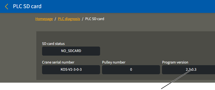
- The "PLC SD card" window appears.
- Read the program version of ABUControl in the "Program version" description field.
Note:
When using this product manual or when consulting ABUS Service, the program version listed here is particularly relevant. The various version numbers appearing in the "PLC diagnosis" window are only important in individual cases.
Opening the PLC diagnosis page
Overview: Navigation in KranOS |
|---|
User "CUSTOMER" or "SERVICE" 🡪 "PLC diagnosis" |
- Log in to KranOS with user "CUSTOMER" (user level ‚[1]) or "SERVICE" (user level [2]). See "Logging into and registering in KranOS".
- In the start window: Click on the "PLC diagnosis" menu item in the "Settings" menu (three horizontal bars).
Reading diagnosis
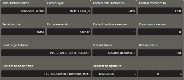
- The "PLC diagnosis" window appears.
- Reading necessary information:
Description field |
Meaning |
|---|---|
"Manufacturer name" |
Name of the manufacturer of the control components |
"Control type" |
Control reference |
"Control manufacturer ID" |
ID of the manufacturer of the control components |
"Control reference ID" |
Control type ID |
"Serial number" |
Control serial number |
"Firmware version" |
Control firmware version |
"Control hardware version" |
Version of the control hardware |
"Coprocessor version" |
Control coprocessor version |
"Boot project status" |
Gives information about the boot application that is saved in the PLC flash memory. |
"SD card status" |
Status of the SD card in the PLC. |
"Battery status" |
Charging status of the PLC battery as a percentage. |
"SoMachine node name" |
Node name in the SoMachine network. |
"Application signature" |
Signature of the application. |
Note:
The various version numbers appearing in this window are only important in individual cases.
Displaying the bus diagnosis
For analysing faults or in conversation with ABUS Service, it can be helpful to see which bus devices were recognised in the bus network. A CAN bus network is in any case present on the crane. A Modbus network may additionally be present.
For this work step, access from a laptop or tablet computer to KranOS is necessary. The user "CUSTOMER" (user level [1]) or "SERVICE" (user level [2]) must be logged in.
Opening the bus diagnosis
Overview: Navigation in KranOS |
|---|
User "CUSTOMER" or "SERVICE" 🡪 "PLC diagnosis" 🡪 "Bus diagnosis" |
- Log in to KranOS with user "CUSTOMER" (user level [1]) or "SERVICE" (user level [2]). See "Logging into and registering in KranOS".
- In the start window: Click on the "PLC diagnosis" menu item in the "Settings" menu (three horizontal bars).
- The "PLC diagnosis" window appears.
- Click on the "Bus diagnosis" menu item in the "Settings" menu (three horizontal bars).
Reading the bus diagnosis
Bus device not found (black background)Found bus device (green background)
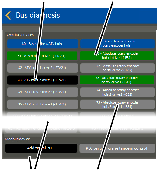
- The "Bus diagnosis" window appears.
- CAN bus devices are displayed in the upper area and Modbus devices are displayed in the lower area.
- All bus devices that were found in the bus network are displayed with a green background.
- All bus devices that were not found in the bus network are displayed with a black background.
- All bus devices which are not available on the current crane according to the customer-specific configuration appear with a grey background.
In principle, all technically feasible bus devices that could appear on a crane with ABUControl are displayed.
Displaying log file
It can be helpful to display the log file for analysing faults or in conversation with ABUS Service.
For this work step, access from a laptop or tablet computer to KranOS is necessary. The user "CUSTOMER" (user level ‚[1]) or "SERVICE" (user level [2]) must be logged in.
Opening the PLC log file
Overview: Navigation in KranOS |
|---|
User "CUSTOMER" or "SERVICE" 🡪 "PLC diagnosis" 🡪 "Log file" |
- Log in to KranOS with user "CUSTOMER" (user level [1]) or "SERVICE" (user level [2]). See "Logging into and registering in KranOS".
- In the start window: Click on the "PLC diagnosis" menu item in the "Settings" menu (three horizontal bars).
- The "PLC diagnosis" window appears.
- Click on the "Log file" menu item in the "Settings" menu (three horizontal bars).
- The "Log file" window appears.
- Click on the "Download log file" button.
Reading the log file
Read the last entries:
"Download log file" button
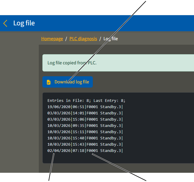
- The last 15 messages of the log file are displayed.
- Every message is displayed in its own line.
- The messages and fault codes are saved in the log file with the date and time.
For further details on fault codes, messages, confirming and designating messages, see "Eliminating errors on the crane with ABUControl".
Viewing the entire log file:
New tab
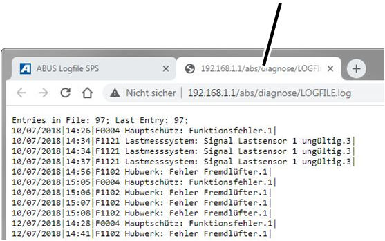
- Click on the "Download log file" button.
- A new tab opens in the browser and the entire log file is displayed.
The log file is comprised of a maximum of 500 entries. If the maximum number of 500 entries is reached, the oldest entries at the beginning of the log file are overwritten. This means that the entries at the beginning of the log file could be more recent than those at the end of the log file.
Displaying PLC sequence diagnosis
It can be helpful to see whether the start of the PLC functioned without faults or at what point a fault occurred, for analysing faults or in conversation with ABUS Service.
For this work step, access from a laptop or tablet computer to KranOS is necessary. The user "CUSTOMER" (user level [1]) or "SERVICE" (user level [2]) must be logged in.
Opening the PLC sequences diagnosis
Overview: Navigation in KranOS |
|---|
User "CUSTOMER" or "SERVICE" 🡪 "PLC diagnosis" 🡪 "PLC sequence diagnosis" |
- Log in to KranOS with user "CUSTOMER" (user level ‚[1]) or "SERVICE" (user level [2]). See "Logging into and registering in KranOS".
- In the start window: Click on the "PLC diagnosis" menu item in the "Settings" menu (three horizontal bars).
- The "PLC diagnosis" window appears.
- Click on the "PLC sequences diagnosis" menu item in the "Settings" menu (three horizontal bars).
Reading the "PLC sequences diagnosis"
Interrupted sequence
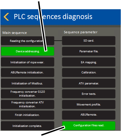
- The "PLC sequences diagnosis" window appears.
- The three sequences "Main sequence", "Sequence parameter" and "Visualization sequence" are displayed.
A sequence is a program sequence in the PLC. All individual steps within a sequence are processed one after the other during the start of the PLC.
The PLC is only ready for use once all sequences have been completely processed up to the last step.
- The last step within a sequence is displayed with a green background: The sequence has been successfully executed right up to the last step.
- Another step within a sequence is displayed with a green background: The sequence has only been executed up to the step with the green background. A fault has possibly occurred at this step.
The main sequence and the parameter sequence are linked together. The main sequence starts at the first step in the parameter sequence. If the parameter sequence has been processed, the main sequence is further processed from the second step.
Setting date and time
The date and time at which this fault occurred are included in the information saved in the log file. This can be helpful for analysing faults or in conversation with ABUS Service.
If the crane is switched off, the time is saved in the PLC and continues on via the internal battery in the PLC.
For this work step, access from a laptop or tablet computer to KranOS is necessary. The user "Service" (user level [2]) must be logged in.
Opening time setting
Overview: Navigation in KranOS |
|---|
User "SERVICE" 🡪 "PLC diagnosis" 🡪 "Set PLC time" |
- Log in to KranOS with user "Service" (user level [2]). See "Logging into and registering in KranOS".
- In the start window: Click on the "PLC diagnosis" menu item in the "Settings" menu (three horizontal bars).
- The "PLC diagnosis" window appears.
- Click on the "Set PLC time" menu item in the "Settings" menu (three horizontal bars).
Setting date and time
Input fields for date"Accept browser time" button
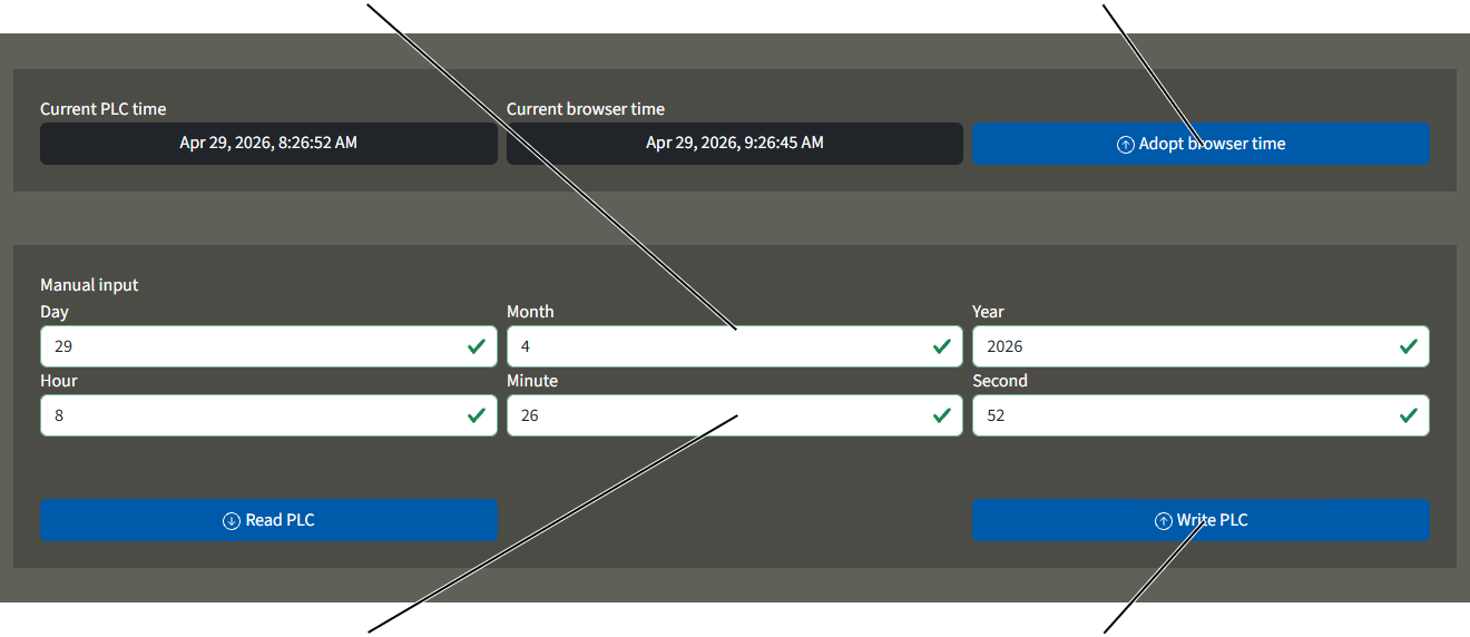
- The "Set PLC time" window appears.
Take date and time from the browser:
- Click "Accept browser time" button.
- The date and time are taken from the browser.
Enter date and time manually.
- Input in the date and time input fields.
- Click on the "Write PLC" button.
- The PLC saves the date and time.
Changing the PLC battery
The PLC battery has a lifespan of about 4 to 5 years and should therefore be changed after about 4 years.
Battery type: CR2032.
Battery holder
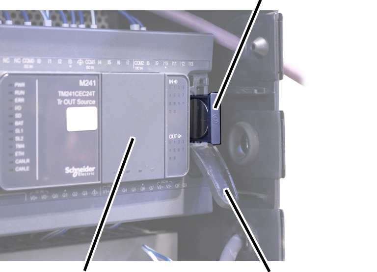
- Switch off the crane. See "Switching off the crane".
- Open hoist panel.
- Open the cover on the PLC.
- Remove the battery holder.
- Remove empty battery.
Dispose of the empty battery in an environmentally sound manner.
- Observe the polarity and insert the new CR2032 type battery.
- Push the battery holder into the PLC.
Inserting or removing the SD card in the PLC
SD card
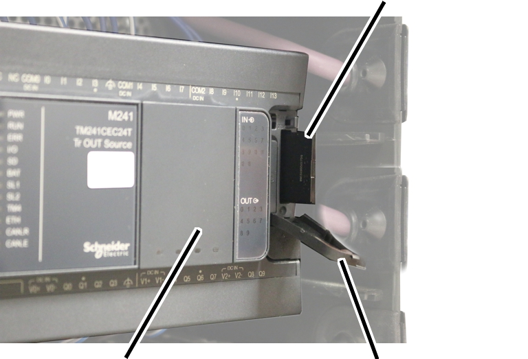
- Switch off the crane. See "Switching off the crane".
- Open hoist panel.
- Open the cover on the PLC.
- Remove or insert the SD card in the PLC.
- Switch the crane on.
If an SD card is removed or inserted in the PLC during running operation:
- The crane control restarts automatically and runs through the sequence for starting ABUControl.
Crane control without SD card
The crane should always be operated with an inserted SD card. If the crane was switched off without an SD card, the error message "NoSdCard" is shown.
Overview: Device addresses
The device address is a digital unique address of each CAN bus device in the CAN bus network, via which the PLC and the respective CAN bus device exchange data. Each CAN bus device must have its own unique device address. If two CAN bus devices inadvertently have the same device address there will be a conflict and a fault is displayed.
The device address can be automatically set at many CAN bus devices. For this purpose, the CAN bus devices are set to a base address at the factory (base addresses usually end with "0"). This base address is otherwise not used in the CAN bus network.
If the PLC cannot find a CAN bus device in the CAN bus network when switched on and instead finds a CAN bus device with a base address, it can be assumed that this CAN bus device has just been replaced. Therefore the base address is converted to the device address of the missing CAN bus device.
CAN bus device |
Base address |
|---|---|
Crane travel frequency converter |
10 |
Trolley travel frequency converter |
20 |
Hoist frequency converter, brand: "Schneider" |
30 |
Inclinometer on the trolley |
40 |
Hoist frequency converter, brand: "Siemens" |
50 |
Absolute rotary encoder |
70 |
LED matrix display |
100 |
Parametrizing frequency converters
When starting the crane, the parameters of the frequency converter are read out and compared with the specified configuration of the PLC. If the parameters do not match, the parameters are automatically transferred again to the respective frequency converter.
The parameters can also be manually transferred again.
For this work step, access from a laptop or tablet computer to KranOS is necessary. The user "SERVICE" (user level [2]) must be logged in.
Opening selection for movement profile
Overview: Navigation in KranOS |
|---|
User "SERVICE" 🡪 "Movement profile" |
- Log in to KranOS with user "SERVICE" (user level [2]). See "Logging into and registering in KranOS".
- In the start window: Click on the "Movement profile" menu item in the "Settings" menu (three horizontal bars).
Starting parametrization

- The "Movement profile" window appears.
- Click the button "Completely reparametrize the frequency converter".
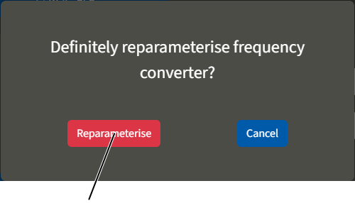
- The query "Do you really want to reparameterize the frequency converter?" appears.
- Click the "Reparameterize" button.
- Switch off the crane at the circuit isolator or mains switch.
- Wait 60 s.
- Switching the crane on again
- ABUControl will restart.
- The frequency converter will additionally be parametrized during the restart.
Resetting frequency converter and measuring hoist motor again
The hoist motor is electrically measured when the crane is started. During the measurement, certain electrical values of the hoist motor are checked with a test current. These measurement results are compared by the frequency converter with the measurement results from the initial start-up of the crane at the commissioning and the frequency converter is set accordingly. In this way, the frequency converter can take into account the thermal state of the hoist motor during running operation.
The measurement can be deactivated upon starting the crane. See "Setting advanced parameters for hoist profile". The thermal state of the hoist motor is then no longer taken into account.
With this function, the measurement from the initial start-up of the crane at the commissioning is deleted and the parameters are transferred again. The scope of the parameter transfer is the same as in the section "Parametrizing frequency converters".
For this work step, access from a laptop or tablet computer to KranOS is necessary. The user "SERVICE" (user level [2]) must be logged in.
Opening selection for movement profile
Overview: Navigation in KranOS |
|---|
User "SERVICE" 🡪 "Movement profile" |
- Log in to KranOS with user "SERVICE" (user level [2]). See "Logging into and registering in KranOS".
- In the start window: Click on the "Movement profile" menu item in the "Settings" menu (three horizontal bars).
Starting parametrization and measuring the hoist motor again
"Reset frequency converter to factory setting" button
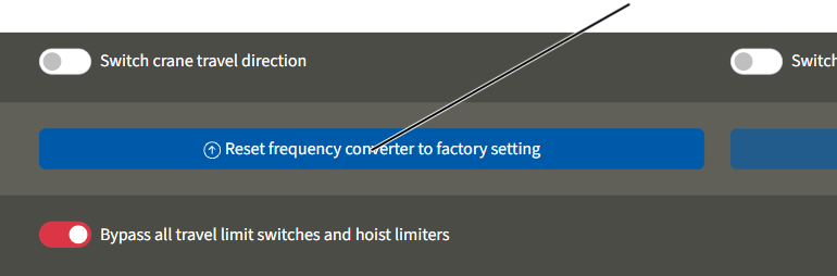
- The "Movement profile" window appears.
- Click the "Reset frequency converter to factory setting" button.
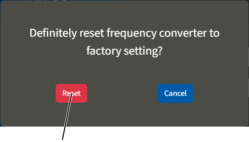
- The query "Do you really want to reset the frequency converter to the factory setting?" appears.
- Click on the "Reset" button.
- The message "F0007: Frequency converter reset. Switch crane on and off" is displayed.
- Switch off the crane at the circuit isolator or mains switch.
- Wait 60 s.
- Make certain that the hoist motors have cooled down to the ambient temperature.
Otherwise the measurement may be falsified and the thermal state of the hoist motor cannot be correctly taken into account.
- Switching the crane on again
- ABUControl will restart.
- On the hoist motor or hoist motors: The motor measurement at the commissioning is performed and the measurement results are saved.
- On all frequency converters: All frequency converters will additionally be reparametrized during the restart.
Replacing the absolute rotary encoder and referencing
The absolute rotary encoder is mounted on the gear limit switch and determines the exact position of the cable drum, and then reports this to the PLC.
For this work step, access from a laptop or tablet computer to KranOS is necessary. The user "SERVICE" (user level [2]) must be logged in.
Only with gear limit switch "GGS" with absolute rotary encoder "AWG"
The absolute rotary encoder is connected to the gear limit switch as a permanent unit and must always be jointly replaced with the gear limit switch.
The circuit board of the absolute rotary encoder may not be disassembled from the gear limit switch and replaced separately.
After replacing the entire unit, the new absolute rotary encoder must be automatically or manually addressed and referenced.
Replacing the absolute rotary encoder
The ABUS gear limit switch "GGS" with absolute rotary encoder "AWG" is fully compatible with the "GPK" hoist limit switches with "Kübler" absolute rotary encoders. If necessary, a "GPK" hoist limit switch can however be installed with a "Kübler" absolute rotary encoder.
- Disassemble the faulty gear limit switch.
- Install new gear limit switch.
See product manual "ABUS gear limit switch with absolute rotary encoder", section "Installing and connecting gear limit switch".
- Reset switching points for the bottom hoist limiter, the top hoist limiter and the backup limiter.
See "Setting switching points for backup limiter and top hoist limiter".
See "Setting switching point for the bottom hoist limiter".
Referencing the absolute rotary encoder
The absolute rotary encoder has to be referenced after it is replaced. This referencing is not part of setting the switching points for the gear limit switch, nor is it part of calibrating the load measuring system, but is instead important for internal calculations (e.g. sway control and discard prognosis). If the absolute rotary encoder is not correctly referenced, malfunctions of the sway control or incorrect calculations in the discard prognosis could occur.
The three switching points of the gear limit switch should already be correctly set before the absolute rotary encoder is referenced.
Measuring the reference point:
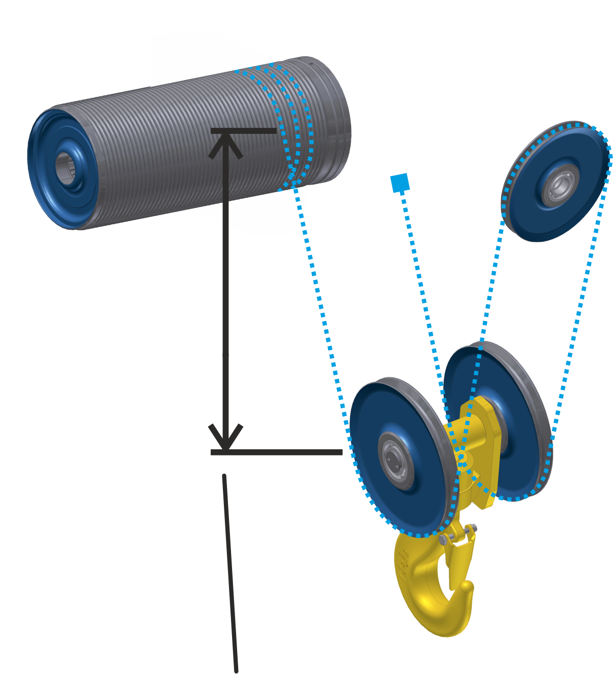
- Move the load hook to a hook position in which the reference point can be easily measured (e.g. about 1.5 m under the highest hook position).
- Measure the vertical distance from the centre of the cable drum to the centre of the deflection roller of the bottom block.
Setting the reference point:
Overview: Navigation in KranOS |
|---|
User "SERVICE" 🡪 "Hoist" 🡪 "Rotary encoder" |
- Log in to KranOS with user "Service" (user level [2]). See "Logging into and registering in KranOS".
- Select the desired hoist (e.g. hoist 1) in the main menu.
- The window for the requested hoist appears.
- Click on the "Absolute rotary encoder" menu item in the "Settings" menu (three horizontal bars).
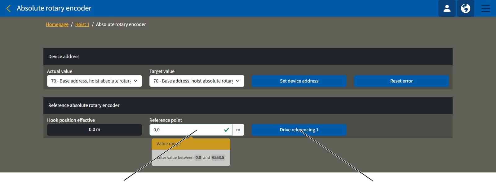
- The "Absolute rotary encoder" window appears.
- Enter the value you measured in the "Reference point" input field.
- Click on the button for the desired drive (e.g. "Drive 1 referencing").
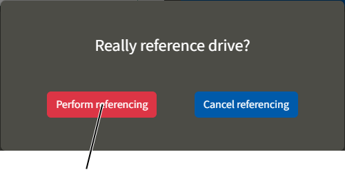
- A confirmation prompt appears.
- Click on the "Perform referencing" button.
- Save the input value.
Overview: Terminating resistor in the CAN bus network
In a CAN bus network such as at ABUControl, a central CAN bus line runs as the backbone. On both ends of the backbone of the CAN bus line the terminating resistors must be set. This means that disruptions in the CAN bus line can be prevented. Further CAN bus devices of the CAN bus network can be connected on this backbone in a radial manner without terminating resistor to a CAN distributor.
Depending on the crane, the CAN bus network can vary greatly. For example, the position of the LED matrix display must be taken into account, as well as the number of trolleys and the type (twin hoist with two hoist drives per trolley), among other considerations.
This section describes both of the two basic CAN bus networks for cranes with one and with two trolleys. For all other CAN bus networks, contact ABUS Service.
When replacing CAN bus devices:
If faulty CAN bus devices are exchanged (e.g. PLC, CAN distributor, LED matrix displays, etc.), the terminating resistor on the new CAN bus device must be switched the same as it was on the faulty CAN bus device.
Only for cranes with one trolley
CAN distributor in the crane panel with the terminating resistor "off"CAN distributor in trolley "off"
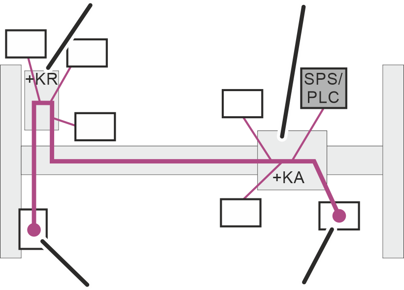
In the CAN bus network of ABUControl for a crane with one trolley, the backbone runs from the trolley on the absolute value encoder through the crane panel (+KR) to the LED matrix display.
The terminating resistors are switched on in the absolute value encoder (AWG) and in the LED matrix display. The terminating resistor in the CAN distributor in the crane panel (+KR) and in the trolley panel (+KA) is disabled.
Only for crane with two trolleys
CAN distributor terminating resistor "off"CAN distributor in trolley 1 "off"
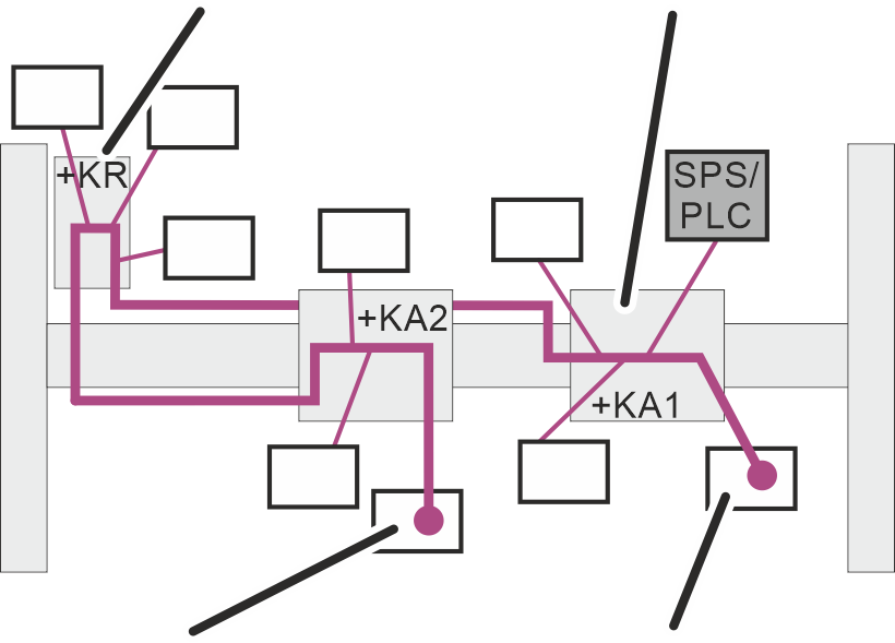
In the CAN bus network of ABUControl for a crane with two trolleys, the backbone runs from the absolute rotary encoder 1 (AWG 1) through the crane panel (+KR) to the absolute rotary encoder 2 (AWG 2).
The terminating resistors are each connected to absolute rotary encoders 1 and 2 (AWG 1 and AWG 2). The terminating resistor in the CAN distributor in the crane panel (+KR) and in the trolley panel (+KA) is disconnected.
Connecting ABUControl with another WLAN network
Normally, the WLAN module establishes its own WLAN network. A WLAN connection can be made with the WLAN network of the crane using a WLAN-enabled computer.
If there is an existing WLAN network of the customer, ABUControl can however also log in to the existing WLAN network as WLAN subscriber.
The settings of the WLAN module (e.g. IP address, SSID, etc.) can be adapted accordingly for this.
- Contact ABUS Service. See "ABUS Service".
Eliminating errors on the crane with ABUControl
If the crane does not function with ABUControl, or does not function as expected, a fault in the ABUControl may be the cause.
Fault codes
A message appears on the LED matrix display:
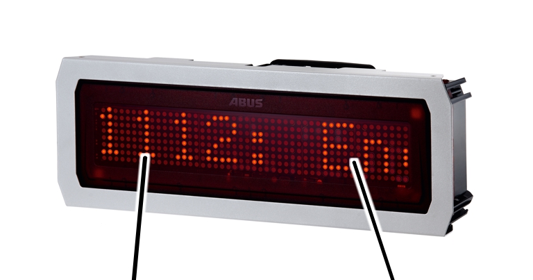
- The LED matrix display shows the fault code and the message from ABUControl as scrolling text.
The text speed can be set in KranOS under the "Crane travel" or "Trolley travel" parameters. See "Setting advanced travel profile parameters (crane travel profile, trolley travel profile)".
Acknowledging messages
The displayed messages are divided into three categories, depending on their seriousness.
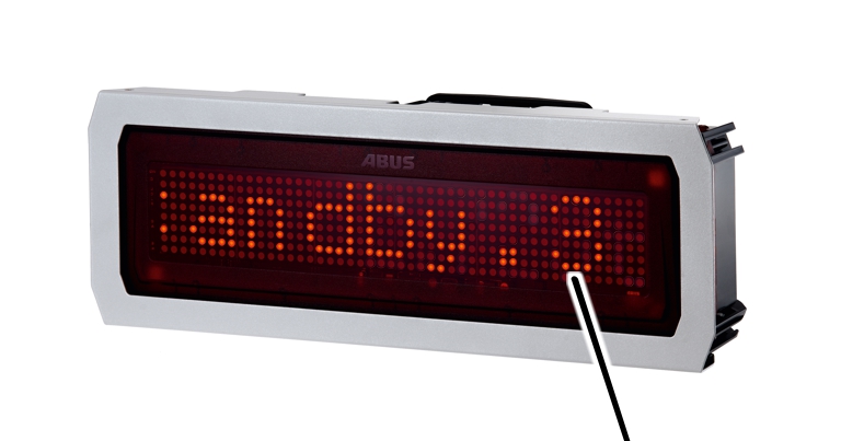
- The category is displayed at the end of the message as ".1", ".2" or ".3".
- ".3": Information message. The crane can continue to be normally operated.
To acknowledge the message display, press the emergency stop button or horn.
- ".2": Not a serious error. The emergency stop function is triggered, the crane comes to a standstill.
To acknowledge the message display, press the emergency stop button or horn.
If the error does not occur again afterward, the crane can continue to be operated normally.
If the error occurs again afterward, the message is not displayed again. The crane can continue to be operated, however, the crane axis affected by the error can only be operated at slow travel speed.
- ".1": Serious error. The emergency stop function is triggered, the crane comes to a standstill.
To acknowledge the message display, press the emergency stop button or horn. If the error arose from a frequency converter, the crane must be switched completely off and then back on again.
If the error does not occur again afterward, the crane can continue to be operated normally.
If the error occurs again afterward, the message is displayed again. The emergency stop function is triggered again.
Assigning messages
The digits in front of the message indicate where (e.g. on which crane axis) the error occurred and which trolley or hoist (in the case of multiple trolleys on the crane) is affected.
Third and fourth digits for the error number
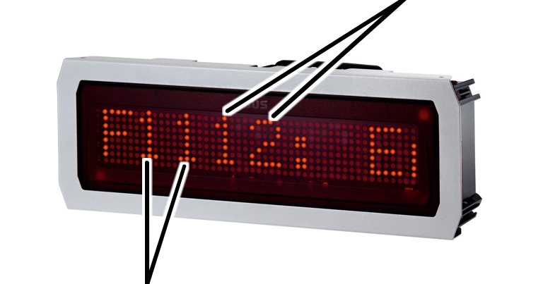
- First and second digits: number of the hoist, the trolley or the crane drive in combination with the crane axis or operating range
- Third and fourth digits: error number
This results in the following combinations for the first two digits:
Digits |
Location |
|---|---|
F00_ _ |
General error |
F11_ _ |
Hoist 1, hoist drive 1 |
F12_ _ |
Hoist 1, hoist drive 2 |
F21_ _ |
Hoist 2, hoist drive 1 |
F22_ _ |
Hoist 2, hoist drive 2 |
F31_ _ |
Hoist 3, hoist drive 1 |
F32_ _ |
Hoist 3, hoist drive 2 |
F13_ _ |
Trolley 1 |
F23_ _ |
Trolley 2 |
F33_ _ |
Trolley 3 |
F14_ _ |
Crane travel drive, frequency converter 1 |
F24_ _ |
Crane travel drive, frequency converter 2 (only with electronic track guidance system and 4-wheel crane travel drive) |
"Hoist drive 2" (F_2_ _) is only used with twin hoists. All other hoists have only one hoist drive (F_1_ _)
"Hoist 2" and "Hoist 3" as well as "Trolley 2" and "Trolley 3" apply to cranes with two or three trolleys.
A crane normally has one frequency converter for both crane travel drives (F14_ _). For cranes with an electronic track guidance system, each of the two crane travel drives has its own frequency converter (F14_ _ and F24_ _). For 4-wheel crane travel drives with greater power consumption of the motors, the four drives can also be divided between two frequency converters.
Digits |
Location |
|---|---|
F40_ _ |
Crane distancing system |
F41_ _ |
Bypass control |
F51_ _ |
Trolley distancing system, Trolley 1 |
F52_ _ |
Trolley distancing system, Trolley 2 |
F53_ _ |
Trolley distancing system, Trolley 3 |
F60_ _ |
Overrun protection |
Overview of messages
General information |
|---|
"F0001: Standby.3" The crane is switched on and in standby mode. To use the crane, unlock emergency stop button or log in transmitter. |
"F0003 PLC: Writing to SD card failed.3" An error occurred when saving data on the SD card in the PLC. Check the SD card; if necessary, insert a new SD card. |
"F0004 Main contactor: Malfunction.1" The main contactor is switched on although it should be switched off, since the emergency stop button was pressed. |
"F0032: Teach position.3" The teach-in function is activated in the positioning control. |
"F0048: Hook assistant limited.3" The hook assistant can only be used to a limited extent; for example, lifting is not possible, or the crane cannot be moved in a particular direction. |
Hoist |
|---|
"F_ _05 Hoist: Motor measurement failed.1" The electrical measurement of the hoist motor during switching on of the crane was unsuccessful. |
"F_ _17 Hoist: Backup limiter started up.1" The load hook has overrun the switching point of the top hoist limiter and has triggered the backup limiter. Check the switching point and gear limit switch. |
„F_ _20 Hoist: Max. hook height exceeded.1" The load hook has exceeded the maximum set hook height. |
"F_ _26: Hoist: Wire rope wear above 80 %.3" The wire rope has reached 80% of its maximum acceptable wear. Have a regular inspection performed. |
"F_ _27: Hoist: Caution! Wire rope wear above 100 %.3" The wire rope has reached 100% of its maximum acceptable wear. Do not continue working with the crane. Have a regular inspection performed. |
"F_ _31 Hoist: Speed too high/low.1" The actual speed of the hoist (measured by the absolute rotary encoder) exceeds the tolerance limits (too high/too low) as compared to the set speed of the hoist. |
"F_ _32 or F_ _33 Hoist synchronisation: Deviation too great.1" In the synchronisation control of two hoists for a crane with two hoists or with two cranes in tandem operation, the height difference between the two load hooks is too great when lifting or lowering. |
„F_ _35 Frequency converter hoist: Speed: Deviation too great.1" There is a discrepancy between the measured speed and the set speed on the hoist's frequency converter. |
"F_ _36 Super-precision lifting: Switching failed.1" The contactors for switching between the windings did not respond. |
"F__37 Hoist: Error in slack-rope detection.3" An error occurred during slack-rope detection initialisation. Acknowledge error and repeat procedure. |
Trolley |
|---|
"F_ _25 Trolley travel synchronisation: Deviation too great.1" In the synchronisation control of two trolleys with a crane with multiple trolleys, the difference in distance between the two trolleys is too great during trolley travel. |
"F_ _26 Trolley travel synch. in tandem op.: Dev. too great.1" In the synchronisation control of two trolleys with two cranes in tandem operation, the difference in distance between the two trolleys is too great during trolley travel. |
"F_ _27 Trolley travel distance sensor: Outside trav. range r.1" The distance sensor for trolley travel to the right detected that the upper limit value was exceeded or the measured value fell below the lower limit value. |
"F_ _28 Trolley travel distance sensor: Outside trav. range l.1" The distance sensor for trolley travel to the left detected that the upper limit value was exceeded or the measured value fell below the lower limit value. |
"F_ _29 Trolley travel distance sensor r: Diagnosis fault.1" Diagnostic error in distance sensor for trolley travel to right. At a standstill, the distance sensor is internally tested at regular intervals. For this testing, the outputs of the distance sensor are briefly switched. |
"F_ _30 Trolley travel distance sensor l: Diagnosis fault.1" Diagnostic error in distance sensor for trolley travel to left. At a standstill, the distance sensor is internally tested at regular intervals. For this testing, the outputs of the distance sensor are briefly switched. |
"F_ _40 Frequency converter: speed: deviation too high.1" There is a discrepancy between the measured speed and the set speed on the hoist's frequency converter. |
"F_ _41 Trolley travel: Dist. sensor right: Travel dir. reversed.1" The trolley runs in a different travel direction (trolley travel frequency converter rotation direction) than detected by the distance sensor for "trolley travel to right". |
"F_ _42 Trolley travel: Dist. sensor left: Travel dir. reversed.1" The trolley runs in a different travel direction (trolley travel frequency converter rotation direction) than detected by the distance sensor for "trolley travel to left". |
Trolley |
|---|
"F_ _49 Trolley travel right: contactor does not switch on.1" When the button for "trolley travel right" is pressed, the contactor does not switch on. |
"F_ _50 Trolley travel right: contactor does not switch off.1" When the button for "trolley travel right" is released, the contactor does not switch off. |
"F_ _51 Trolley travel left: contactor does not switch on.1" When the "Trolley travel left" button is pressed, the contactor does not engage. |
"F_ _52 Trolley travel left: contactor does not switch off.1" When the "Left trolley travel" button is released, the contactor does not switch off. |
"F_ _53 Trolley travel fast: contactor does not switch on.1" When the button for "trolley travel fast" is pressed, the contactor does not switch on. |
"F_ _54 Crane travel fast: contactor does not switch off.1" When the button for "trolley travel fast" is released, the contactor does not switch off. |
Crane travel |
|---|
"F_ _20 Crane travel synch. in tandem op.: Dev. too great.1" In the synchronisation control of the crane drives with two cranes in tandem operation, a difference between the two cranes which is too great occurred during crane travel. |
"F_ _28 Crane travel distance sensor: Outside trav. range f.1" The distance sensor for crane travel forward detected that the upper limit value was exceeded or the measured value fell below the lower limit value. |
"F_ _29 Crane travel dist. sensor: Outside trav. range back.1" The distance sensor for crane travel back detected that the upper limit value was exceeded or the measured value fell below the lower limit value. |
"F_ _30 Crane travel distance sensor f: Diagnosis fault.1" Diagnostic error in distance sensor for crane travel forward. At a standstill, the distance sensor is internally tested at regular intervals. For this testing, the outputs of the distance sensor are briefly switched. |
"F_ _35 Frequency converter crane travel: Speed: Dev. too great.1" There is a discrepancy between the measured speed and the set speed on the hoist's frequency converter. |
"F_ _31 Crane travel distance sensor back: Diagnosis fault.1" Diagnostic error in distance sensor for crane travel back. At a standstill, the distance sensor is internally tested at regular intervals. For this testing, the outputs of the distance sensor are briefly switched. |
"F_ _37 Crane: Distance sensor fwd: Travel dir. reversed.1" The crane runs in a different travel direction (crane travel frequency converter rotation direction) than detected by the distance sensor for "crane travel forward". |
"F_ _38 Crane: Distance sensor back: Travel dir. reversed.1" The crane runs in a different travel direction (crane travel frequency converter rotation direction) than detected by the distance sensor for "crane travel back". |
Crane travel |
|---|
"F_ _44 Safety: safe stop (STO) in the limit switch zone.3" Thanks to the safety PLC, the crane's limit switch zone triggers a safe stop (STO) when the switch point is crossed. |
"F_ _45 Crane travel forward: contactor does not switch on.1" When the button for "crane travel forward" is pressed, the contactor does not switch on. |
"F_ _46 Crane travel forward: contactor does not switch off.1" When the "Crane forward" button is released, the contactor does not switch off. |
"F_ _47 Crane travel back: contactor does not switch on.1" When the button for "crane travel back" is pressed, the contactor does not switch on. |
"F_ _48 Crane travel back: contactor does not switch off.1" When the "Crane back" button is released, the contactor does not switch off. |
"F_ _61 Crane travel fast: contactor does not switch on.1" When the button for "crane travel fast" is pressed, the contactor does not switch on. |
"F_ _62 Crane travel fast: contactor does not switch off.1" The contactor does not switch off when releasing the "Crane travel fast" button. |
Overview of messages for redundant travel limit switches and anti-collision devices
With a redundant travel limit switch, a crane distancing system, or trolley distancing system, two cross-type limit switches or light barriers are used on a switching point in order to additionally increase the level of safety. If both cross-type limit switches or light barriers do not simultaneously trigger when the switching point is run over, the corresponding message is displayed. Nevertheless, the crane or trolley brakes in accordance with the function.
Crane travel |
|---|
"F_ _26 Crane travel: Redundant shut-down: Sw. status differs.3" |
"F_ _27 Crane travel: Red. brake funct.: Sw. status differs.3" |
Crane distancing system |
|---|
"F_ _16 Crane dist. sys.: Red. shut-down 1/2 f: Sw. status diff.3" 1/2 f: Sw. stat. diff.3" |
"F_ _17 Crane dist. sys.: Red. shut-down 1/2 b: Sw. status diff.3" 1/2 b: Sw. stat. diff.3" |
"F_ _18 Crane dist. sys.: Red. shut-down 1/2 f/b: Sw. stat. diff.3" 1/2 f/b: Sw. stat diff.3" |
"F_ _19 Crane dist. sys.: Red. brake fnct. 1/2 f: Sw. stat. diff.3" |
"F_ _20 Crane dist. sys.: Red. brake fnct. 1/2 b: Sw. stat. diff.3" |
"F_ _21 Crane dist. sys: Red. brake fnct. 1/2 f/b: Sw. stat diff.3" |
Trolley distancing system |
|---|
"F_ _16 Trolley dist. sys.: Red. shut-down 1/2 r: Sw. stat. diff.3" 1/2 r: Sw. stat diff.3" |
"F_ _17 Trolley dist. sys.: Red. shut-down 1/2 l: Sw. stat. diff.3" 1/2 l: Sw. stat diff.3" |
"F_ _18 Trolley dist. sys: Red. shut-down 1/2 r/l: Sw. stat diff.3" 1/2 r/l: Sw. stat diff.3" |
"F_ _19 Trolley dist. sys: Red. brake fnct. 1/2 r: Sw. stat diff.3" |
"F_ _20 Trolley dist. sys: Red. brake fnct. 1/2 l: Sw. stat diff.3" |
"F_ _21 Tr. dist. sys: Red. brake fnct. 1/2 r/l: Sw. stat diff.3" |
The LED matrix display shows "WAITING":
Even several minutes after the crane's power supply has been switched on, the LED matrix display still shows "WAITING".
- The LED matrix display is not receiving signals from the crane control. Possible cause: the PLC is faulty or defective.
- If the crane starts after a short delay but the LED matrix display still shows "WAITING", the LED matrix display is faulty or the cable leading to the LED matrix display is damaged.
The LED matrix display shows "No Signal":
- The LED matrix display is has already received valid signals from the crane control. However, they have been interrupted or are faulty.
Displaying messages in KranOS
The current fault codes and messages from ABUControl, fault codes from the frequency converter as well a log file of all previous messages can be displayed in KranOS.
For this work step, access from a laptop or tablet computer to KranOS is necessary. The user "CUSTOMER" (user level ‚[1]) or "SERVICE" (user level [2]) must be logged in.
Fault code from frequency converter
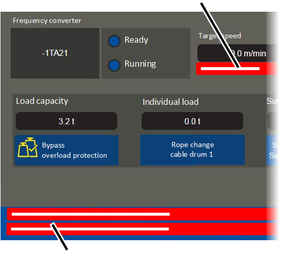
Display of the current messages from ABUControl:
- The current error messages from ABUControl for the respective crane axis are shown in the lower area of the windows of the crane axes.
Display of the fault code from the frequency converter:
- The fault code from the frequency converter is shown in the "Frequency converter" area in the window for the corresponding crane axis.
- In addition, ABUControl displays the fault code from the frequency converter together with the message "F_ _ 01: Hoist: Frequency converter fault code: _ _ _", "F_ _ 01: Trolley: Frequency converter fault code: _ _ _" or "F_ _ 01: Crane: Frequency converter fault code: _ _ _" in the lower area as a collective message.
Display of the log file:
See "Displaying log file".
ABUS Service
Only in Germany
- If available, have the product number, serial number and customer number handy.
- Call the ABUS Service Centre:
- Phone: +49-2261-37-237
- If calling outside the usual business hours, leave a message on the answering machine.
- ABUS Service will return your call promptly.
- If necessary, send a description of the problem by fax or e-mail:
- Fax: +49-2261-37-265
- E-mail: service@abus-kransysteme.de
Only outside Germany
- Call the local ABUS branch or crane service partner.
Your local ABUS branch or crane service partner will provide details of contact data, contacts and availability.