
AT A GLANCE:
General information
This section applies to anyone who lifts loads using the crane, performs work on the crane, or works nearby.
At the start
Using this product manual
The following symbols are used in this product manual:
- This is an instruction regarding an action and prompts you to perform a work step.
- This is the result of an action and describes what happens on the device.
- This is a list.
Only with...
A section that appears in a box framed by a dashed line is only applicable for certain types, versions or options. The condition to which the section applies is specified at the beginning in the heading “Only with...”.
Instructions for the product manual
Read the product manual through carefully before starting work. Also be sure to observe additional product manuals for accessories and components.
Afterwards, keep the product manual available in the vicinity of the crane. It must be accessible to all who work with or on the crane.
If the crane is sold on or hired out, always provide the product manual together with the crane.
Proper use
The cantilever support serves as the superstructure for an ABUS suspended rail system and safely transfers the resulting loads from the operation of the crane installation into the structure or building. The cantilever support must only be operated with crane installations that are statically designed for the loads of the superstructure. Deviations from this or changes in use must be checked statically and require separate approval.
Regulations
The installation has been built and tested according to European standards, rules and regulations applicable at the time of its manufacture. The conventions applied during design and construction are specified in the Declaration of Conformity or the Declaration of Incorporation. The conventions must also be observed for installation, operation, inspection and maintenance, as must the applicable occupational health and safety regulations.
Which provision applies in individual cases will greatly depend on the crane’s use and the national regulations. Review and observe all applicable and current regulations, including the occupational health and safety regulations. Refer also to the Declaration of Conformity or Declaration of Incorporation.
Warranty
- ABUS assumes no liability for damages that were caused by improper use, inadequately trained personnel, incorrect performance of work, nor for any changes, reconstruction or other modification of the crane or crane components which were not approved by ABUS.
- Any warranty claim becomes invalid if components were modified without consent, the crane or crane components were installed, used or serviced in any way other than that described in this product manual, or if parts other than original ABUS replacement parts were used.
- Safe operation of the crane or crane components is only guaranteed if original ABUS replacement parts are used.
Transporting the cantilever support on a lorry
Observe the following points amongst others:
- Secure the load according to regional regulations.
- Cover unpainted surfaces and openings with film and secure with adhesive tape.
Disposing of the cantilever support
If the cantilever support must be disposed of:
- Dismantle the cantilever support as far as is possible.
- Observe local regulations concerning disposal and recycling.
- Dispose of the individual parts sorted by material in an environmentally sound manner.
- Parts of the cantilever support that have been repainted must be disposed of in accordance with the paint manufacturer’s specifications.
The cantilever support
Description of the device
Cantilever support overall view:
1
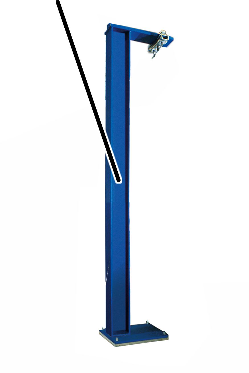
- 1: Cantilever support
Detailed view of cantilever and cantilever support
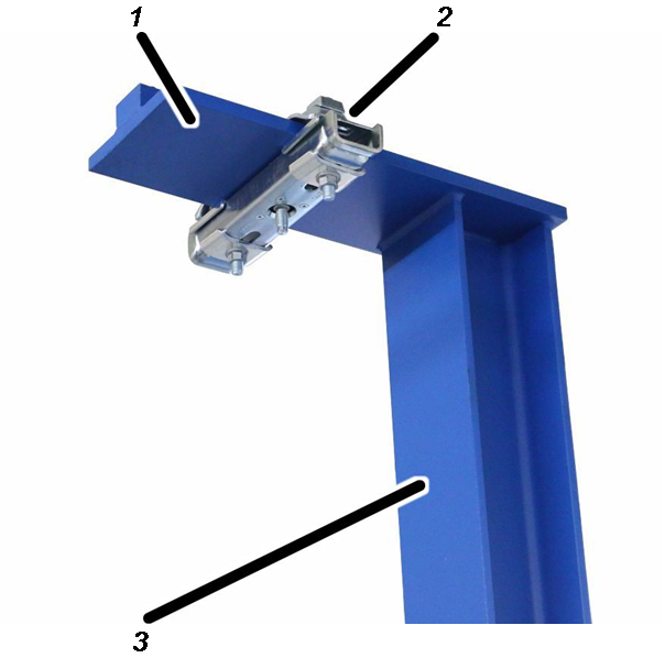
- 1: Cantilever
- 2: Ceiling-mounted bracket with flange clamp
- 3: Support
Detailed view of dowel plate and cantilever support:
The dowel plate has either 8 or 10 holes and is anchored by 4 or 6 dowels depending on the project.
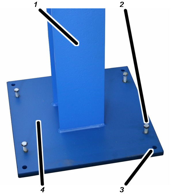
- 1: Support
- 2: Set-screw
- 3: Drilled hole for dowel
- 4: Dowel plate
Dowel:
Four or six of these dowels are combined in a packet.
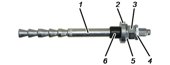
- 1: Anchor rod
- 2: Ball socket
- 3: Hexagonal nut
- 4: Lock nut
- 5: Spherical washer
- 6: Clamping bush
Performance features
The cantilever support:
- The cantilever support consists of the dowel plate and support with the cantilever.
- The support is an I-beam welded vertically onto the dowel plate.
- The dowel plate is anchored in the building floor with dowels.
The cantilever support with one sided cantilever (version):
- The cantilever support has a one sided cantilever on which a ceiling-mounted bracket is fitted using a flange clamp, allowing an HB crane runway to be attached to it.
The cantilever support with two sided cantilever (T-support) (version):
- The cantilever support has a two sided cantilever on which a flange clamp is fitted on each of the two sides, allowing an HB crane runway to attached to each side.
Technical data
The technical data for this cantilever support is always project-specific and is included in the corresponding planning documents. The cantilever supports are manufactured in individual overall heights.
Installing and connecting
This section applies to anyone who works on the crane prior to its use
The end user of the crane is responsible for the proper qualifications of the commissioning personnel.
Examples of qualified persons:
- Persons with comprehensive knowledge from specialist training in engineering and in the electrical systems of cranes.
- Persons with sufficient experience in the operation, installation and maintenance of cranes.
- Persons with comprehensive knowledge regarding the relevant technical rules, directives and safety regulations applicable in the respective country.
- Persons receiving regular training from ABUS.
ABUS assumes no liability for damage due to incorrectly performed commissioning work done by unqualified personnel.
ABUS recommends having the commissioning work performed by the ABUS assembly team.
- Persons with basic knowledge of general dowel technology, their mode of operation and conditions of use.
- Persons with experience in anchoring and the assembly of dynamic loads in accordance with approvals.
- Persons with proof of training from dowel manufacturers of the corresponding dowels.
Checking the requirements
The following requirements must be met in order for the cantilever support to be installed.
- The base plate must be from normal concrete with reinforcement. The quality should be at least B25 (C20/25) and a maximum of B55 (C50/60).
- The base plate must be adequate for the expected loads of the cantilever support. There must be a structural verification for this, which must be presented to the relevant specialist personnel during the acceptance phase, before initial commissioning.
- The base plate must be at least as thick as is specified in the table. The minimum clearance of the drilled holes to joints and edges must be observed.
Highbond dynamic anchors |
Minimum thickness of base plate |
Minimum clearance to joints and edges |
|---|---|---|
M12 |
150 mm |
150 mm |
M16 |
180 mm |
200 mm |
- The base plate must be single-layered and is not permitted to have any other layers (screed, tiles, etc.).
If there is an additional layer:
- Remove the coating in dowel plate area and 100 mm around the dowel plate.
Check technical approval for project processing
Technical approval for project processing must be granted on-site. The following points must be observed for approval:
- It must be ensured that the on-site supporting structure is able to withstand the forces from crane operation. See building statistics on the transmission of forces.The load effects and relevant loads for the crane installation are provided by ABUS.
- The position of the drilled holes must be checked and approved on-site.
- The dowel fixing must be approved on-site.
Installation overview
The following sections describe the installation of the cantilever support.
- First, the preparations for installation are made. See “Preparing for the installation”.
- Then the holes are drilled. See “Drilling the holes”.
- Then the dowels are fitted using injection mortar. See “Fitting the dowel using injection mortar”.
- After that the dowel plate is grouted. See “Grouting the dowel plate”.
- The dowel plate is then screwed into place permanently. See “Fastening the dowel plate”.
- Then the hexagonal nuts are secured and sealed. See “Securing and sealing the hexagonal nuts”.
- Finally, one ceiling-mounted bracket is fitted on a cantilever support with a one sided cantilever and two ceiling-mounted brackets are fitted on a cantilever support with a two sided cantilever. See “Installing the ceiling-mounted bracket”.
Preparing for the installation
- Determine the location to secure the cantilever support and thoroughly clean the concrete surface of the floor of the building in this area of dirt, dust etc.
Erecting the cantilever support
Support
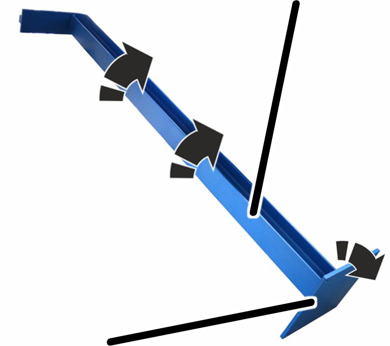
- Erect the cantilever support and secure against falling over.
Aligning the cantilever support
Set-screw
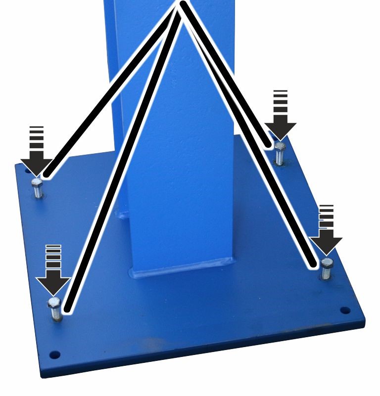
- Screw the set-screws M12x70 (4x or 6x) hand-tight into the dowel plate.
Set-screwDowel plate
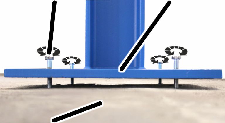
- Fit the spirit level on the support.
- Align the cantilever support perpendicularly using the set-screws (4x or 6x).The gap between the dowel plate and base plate must conform to the specifications in the planning documents.
Drilling the holes
Drilling the holes in the base plate
The aligned dowel plate is used as a template for the drilled holes.
Hammer drill
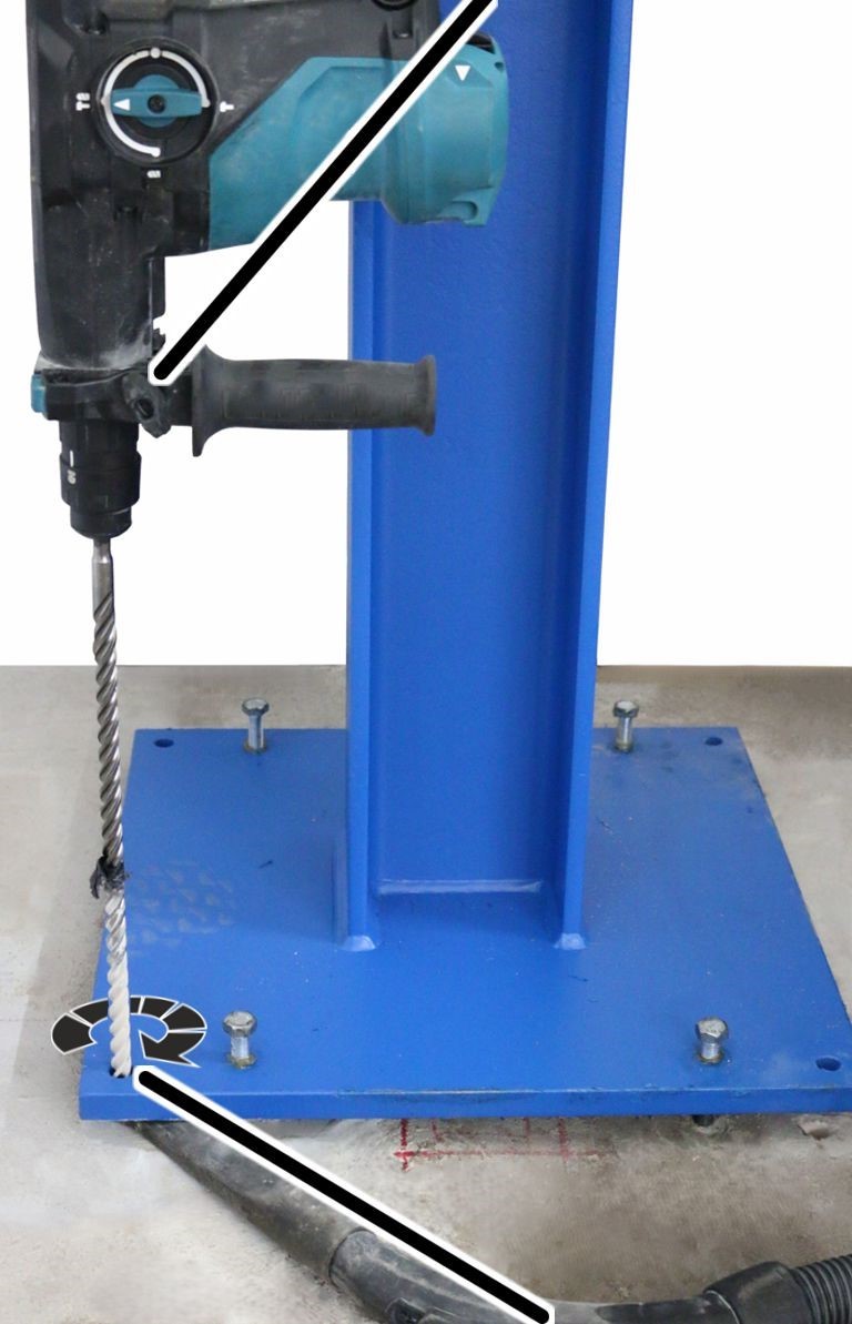
- Clamp the hard metal wall drill with the correct bore in the hammer drill.
Dowel |
Drilled hole diameter d |
|---|---|
M12 |
14 mm |
M16 |
18 mm |
- Observe the depth of the drilled hole and hold the hammer drill so that it is exactly vertical, see planning documents.
Cleaning the drilled holes
Blow-out pump
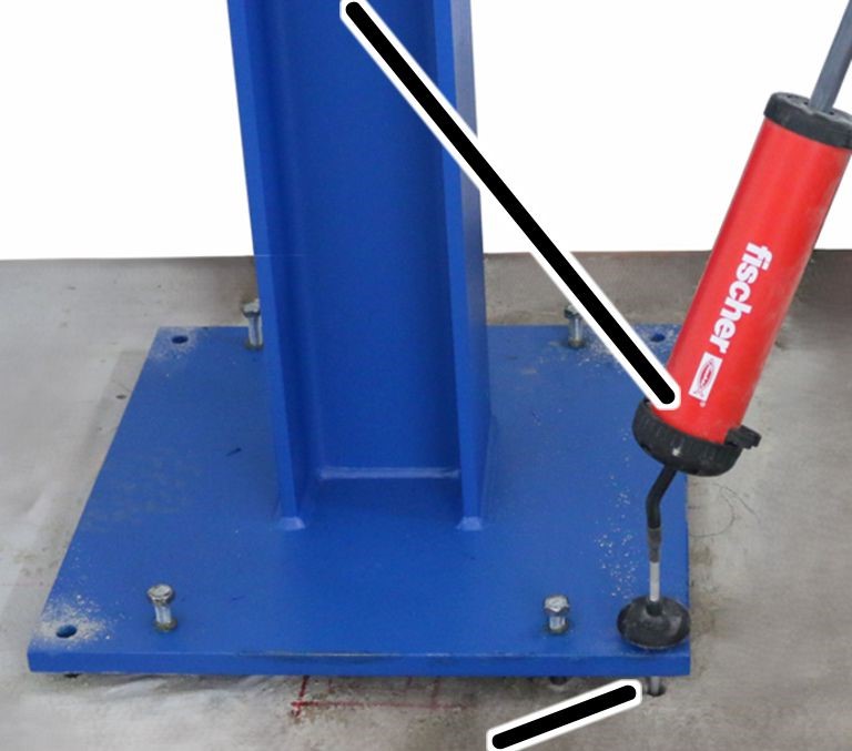
- Blow out all drilled holes twice, working from the drilled hole base using a blow-out pump or oil-free compressed air, and vacuum up the drill dust produced.
Electrically operated screwdriver with
drilled hole brush
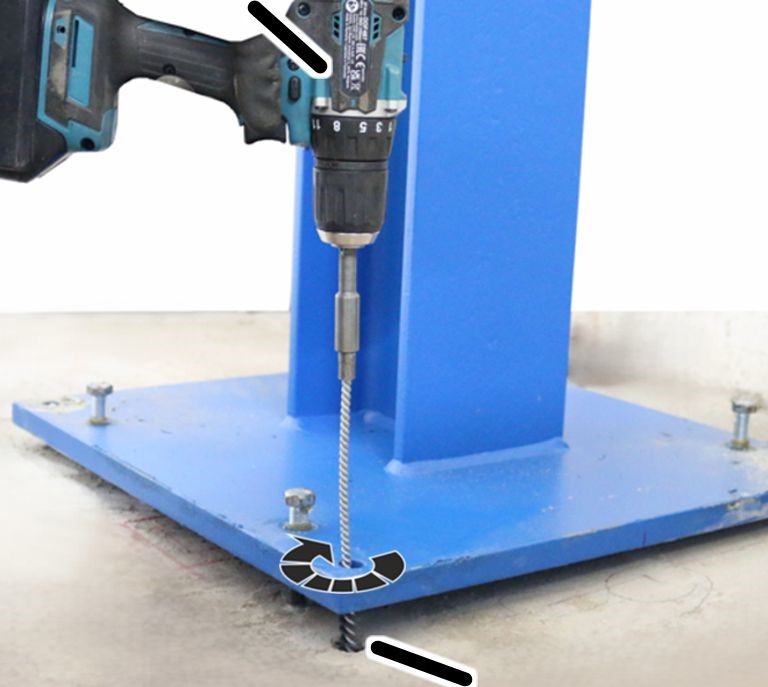
- Brush out all drilled holes twice with the drilled hole brush.
- Blow out the drilled holes and suction out the drill dust twice more.
- Suction out the gap between dowel plate and base plate. No drill dust may get into the drilled holes.
Checking the drilled hole depth
- To test the holes, insert the dowels completely into the drilled holes. The lower edge of the ball socket must rest on the dowel plate.
If a drilled hole is not deep enough:
- Re-drill and clean the hole as previously described.
Fitting the dowel using injection mortar
Preparing the capsule
CapsuleStatic mixer
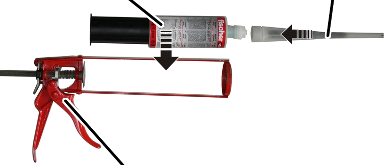
- Unscrew the capsule seal.
- Screw on the static mixer.
- Place the capsule in the pressure gun.
Tip of
static mixerUnmixed
injection
mortar
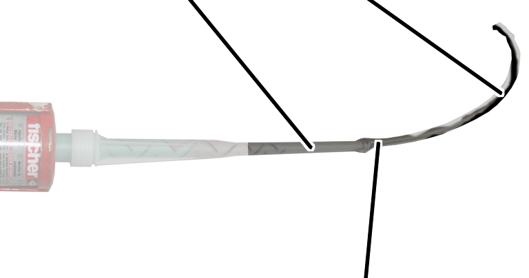
mortar, grey
- Press injection mortar out of the capsule until the injection mortar emerging has been uniformly mixed and is clearly grey in colour. Do not use injection mortar that is not grey in colour.
- In the event of interruptions (e.g. between two dowel fittings), do not unscrew the static mixer from the capsule.
- After each interruption, squeeze out two gun strokes of unused injection mortar and do not use.
- After longer breaks, screw on a new static mixer and again squeeze out the injection mortar for as long as is needed until the discharged injection mortar is clearly grey in colour.
- Injection mortar which is not grey is not mixed correctly and will not set. Do not use any injection mortar which is not grey coloured!
- Setting time of the injection mortar:
Temperature of the capsule |
Setting time [min] |
|---|---|
+ 5°C |
15 min |
+ 20°C |
6 min |
+ 30°C |
4 min |
Filling the drilled hole with injection mortar
Pressure gun with injection mortar
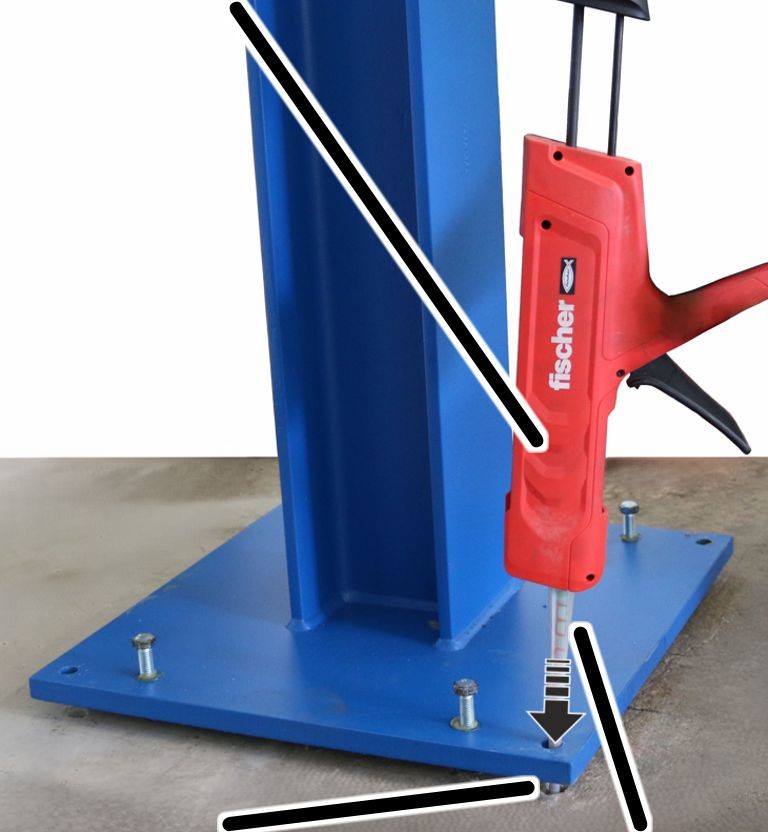
- Read off the necessary quantity of injection mortar from the table. From the base of the drilled hole (through the dowel plate), fill the drilled hole with injection mortar without any bubbles. Read off the quantity used to fill the hole from the scale on the capsule.
Drilled hole |
Quantity of injection mortar required |
|---|---|
M12 |
At least 8 scale units |
M16 |
At least 10 scale units |
- Continue immediately with the next work step (see “Pressing the dowel in”). Otherwise the injection mortar will harden and become unusable.
Pressing the dowel in
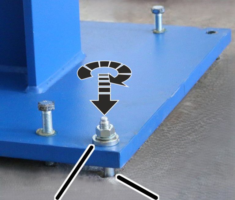
Injection mortar
- Rotate the dowel slightly and while doing so, press it through the dowel plate into the drilled hole. Press the anchor rod so far in that the lower edge of the ball socket touches the dowel plate.
- In the process, some injection mortar will emerge from the drilled hole.
If no injection mortar comes out of the drilled hole:
- Pull the anchor rod immediately out of the drilled hole.
- Fill up the drilled hole with additional injection mortar.
- Insert the anchor rod again as described.
Fitting all the other dowels
- Use the same procedure to fill all the other drilled holes and install the dowels.
- Allow the injection mortar to harden.
Temperature in base plate |
Hardening time [min] |
|---|---|
- 5°C to 0 C |
360 min |
0°C to + 5 C |
180 min |
+ 5°C to + 10°C |
90 min |
+ 10°C to + 20°C |
35 min |
+ 20°C to + 30°C |
20 min |
+ 30°C to + 40°C |
12 min |
Grouting the dowel plate
- Preparing the formwork
Tip:
To fully distribute the quick-drying mortar under the dowel plate, a chain can be placed over the entire width under the dowel plate, for example, and be used to move the quick-drying mortar under the dowel plate. Pull the chain out of the quick-drying mortar before it begins to set.
Dowel plate
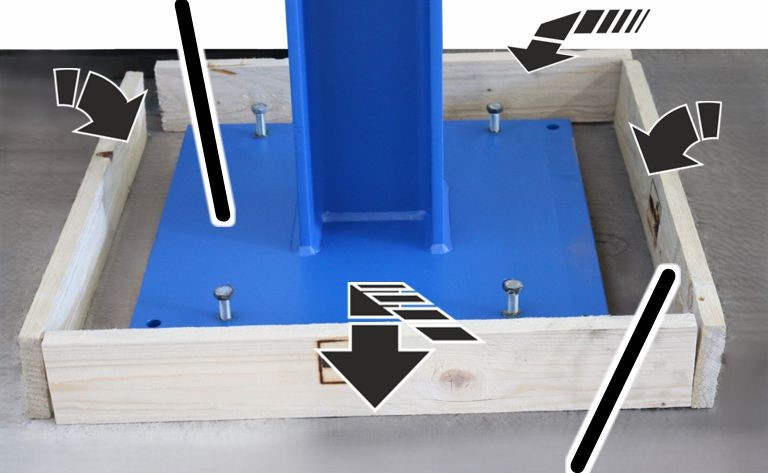
- Lay the supplied formwork around the dowel plate spaced about 2 cm apart and screw the formwork boards together.
- Carefully fix the formwork to the floor of building using fabric adhesive tape.
Mixing the quick-drying mortar
- Only use Pagel quick-drying mortar V2/20.
- Read off the quantity of quick-drying mortar from the table and mix this amount.
See details on the packaging of the quick-drying mortar.
Ø Dowel plate |
Gap between dowel plate and base plate [mm] |
Grout volume [litres] |
Dry mortar mass [kg] |
|---|---|---|---|
500 x 500 |
20 |
4.6 |
9.2 |
550 x 550 |
20 |
5.5 |
11 |
650 x 650 |
20 |
7.5 |
15 |
700 x 700 |
20 |
8.7 |
17.4 |
Pouring out quick-drying mortar
Tip:
To pour out the quick-drying mortar as precisely as possible, a piece of cardboard, for example, can be used as a guiding aid. Using adhesive tape, secure one side of the cardboard on the edge of the base plate and the other side on the support. Pour the quick-drying mortar against the cardboard such that it runs down the sloping surface.
Container with quick-drying mortar
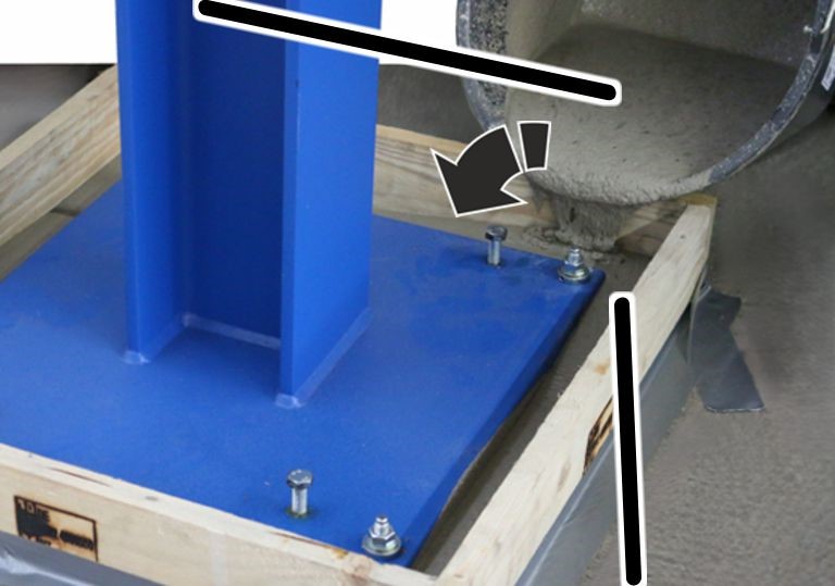
- Pour the quick-drying mortar into the formwork from all sides. The dowel plate must be completely grouted. Fill in as much quick-drying mortar as required for the dowel plate to be about 1 cm deep in the mortar.
- Remove any residue of the quick-drying mortar from the dowel plate and clean spots with water.
Remove the formwork and set-screws.
Once the quick-drying mortar has hardened sufficiently (after around 2 hours):
Dowel plate
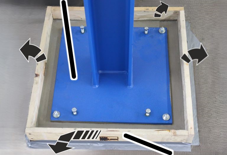
- Remove the formwork and fabric adhesive tape.
- Unscrew all four or sex set-screws from the dowel plate.
- Press the thread protection caps into the threaded holes of the set-screws (4x or 6x).
Fastening the dowel plate
Torque wrench
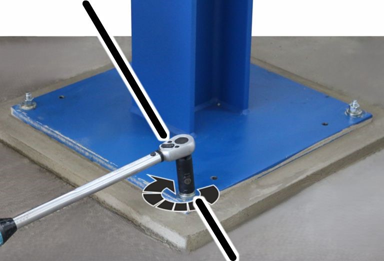
- Tighten all hexagonal nuts with the correct torque.
Type and size |
Tightening torque |
|---|---|
Anchor rod M12 |
40 Nm |
Anchor rod M16 |
60 Nm |
If the hexagonal nuts cannot be tightened with the necessary tightening torque (e.g. because the anchor rod turns with them), the anchor rod is not fitted correctly.
In this case:
- Do not continue installing the cantilever support.
- Call ABUS for further instructions.
Securing and sealing the hexagonal nuts
Screw lock lacquer
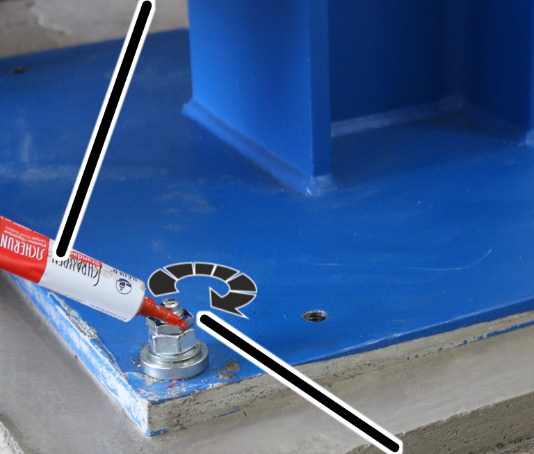
- Screw the lock nuts to the anchor rods. Screw until hand-tight.
- Seal the hexagonal nuts, lock nuts and anchor rods with screw lock lacquer.
Recording the installation
- Glue or attach the labels with approval number, conformity symbol, batch number and EAN code of the anchor rods in the dowel protocol (see page 18).
- Complete the dowel protocol and staple this product manual with the dowel protocol to the crane test log book.
Installing the ceiling-mounted bracket
Only for a cantilever support with one sided cantilever
On cantilever supports with one sided cantilever one ceiling-mounted bracket is secured in each case on the lower flange of the cantilever with flange clamps. An HB crane runway can be suspended from the ceiling-mounted brackets.
Only on cantilever support with two-sided cantilever
(T support)
On cantilever supports with two sided cantilever two ceiling-mounted brackets are secured in each case on the lower flange of the cantilever with flange clamps. Two HB crane runways can be suspended from the ceiling-mounted brackets.
Overview of tightening torques
Dowel
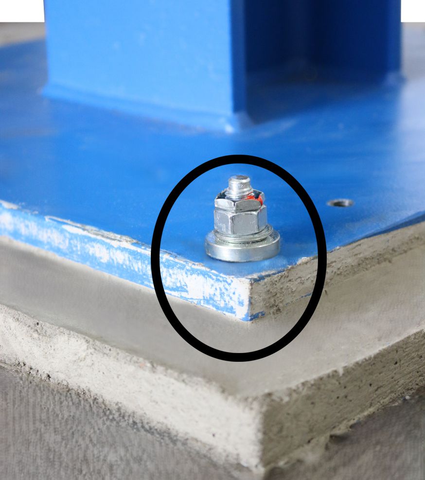
Hexagonal nut |
Tightening torque |
|---|---|
M12 |
40 Nm |
M16 |
60 Nm |
Dowel Protocol
Order number |
|
|---|---|
Building project |
|
Installation company |
Target specifications |
Target specifications |
|||
|---|---|---|---|---|
Dowels used |
FHB dyn |
FHB dyn |
❑ Description agrees |
|
Injection mortar used |
FIS HB 150 C |
FIS HB 150 C |
❑ Description agrees |
|
Number of mounted dowels |
4 or 6 |
4 or 6 |
_____ pieces |
|
Concrete strength according to |
≥ B25 |
≥ B25 |
According to customer specifications B _____ C _____ |
|
Load-bearing thickness of the base plate |
150 mm |
180 mm |
According to customer specifications _____ mm |
|
Drilled hole depth h |
Refer to the |
Refer to the |
_____ mm |
|
Drilled hole nominal diameter d |
14 mm |
18 mm |
_____ mm |
|
Drill cutting diameter |
14 mm |
18 mm |
_____ mm |
|
The hammer drill used bears the test symbol issued by the German test association for masonry drills (e.V. Remscheid) |
❑ yes |
|||
Cleaning the drilled holes |
Blow out x Brush out x Blow out x |
Blow out x Brush out x Blow out x |
___ blown out ___ brushed out ___ blown out |
|
Temperature in the anchor base |
−5 °C to 40 °C |
−5 °C to 40 °C |
_____°C |
|
Distance from drilled holes to edge or joints of concrete component |
150 mm |
200 mm |
_____ mm |
|
Tightening torque |
40 Nm |
60 Nm |
_____ mm |
|
Were the hexagonal nuts tightened with a tested and calibrated torque wrench? |
❑ yes |
|||
Are all the hexagonal nuts secured with lock nuts? |
❑ yes |
|||
Are all the dowels sealed with screw lock lacquer? |
❑ yes |
|||
Was the dowel installation carried out properly according to this product manual |
❑ yes |
|||
_____________ _____________ __________________________ __________________________
Place Date Name in block letters Signature