Upper end carriage
The following sections show how the semi-goliath crane is installed.
─ First, the high-tensile bolts are prepared. See ʺPreparing the high-tensile boltsʺ.
|
|
Upper end carriage |
|
| |
─ The upper end carriage is then mounted to the main girder. See ʺInstalling the upper end carriage on the main girderʺ.
─ Then the other individual parts (crane travel drives, panel,...) are installed on the upper end carriage. See ʺInstalling individual parts on the upper end carriageʺ.
─ Next, the upper end carriage is supported and the trolley secured on the main girder. See ʺSecuring the craneʺ.
|
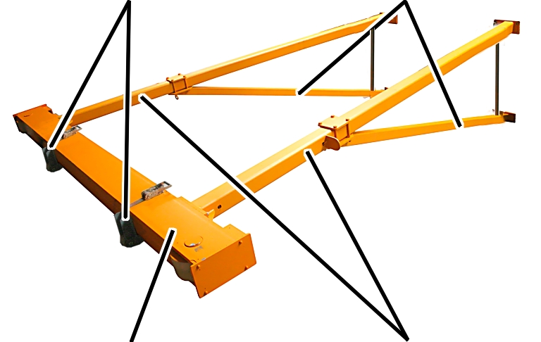
Assembly rollers |
Diagonal braces |
|
| |
|
Lower end carriage |
A-frames |
─ Two assembly rollers are then fastened to the lower end carriage. See ʺAssembling the A-framesʺ.
─ Next, the two A-frames are mounted on the lower end carriage. See ʺAssembling the A-framesʺ.
|
|
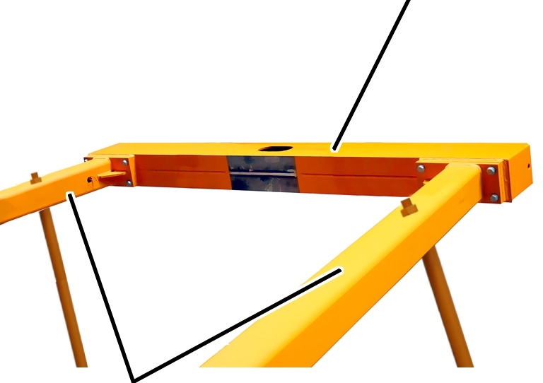
Outer cross head beam |
|
| |
|
A-frames |
|
─ The outer cross head beam is then mounted on the A-frames. See ʺAssembling the cross head beam on the portal supportsʺ.
|
|
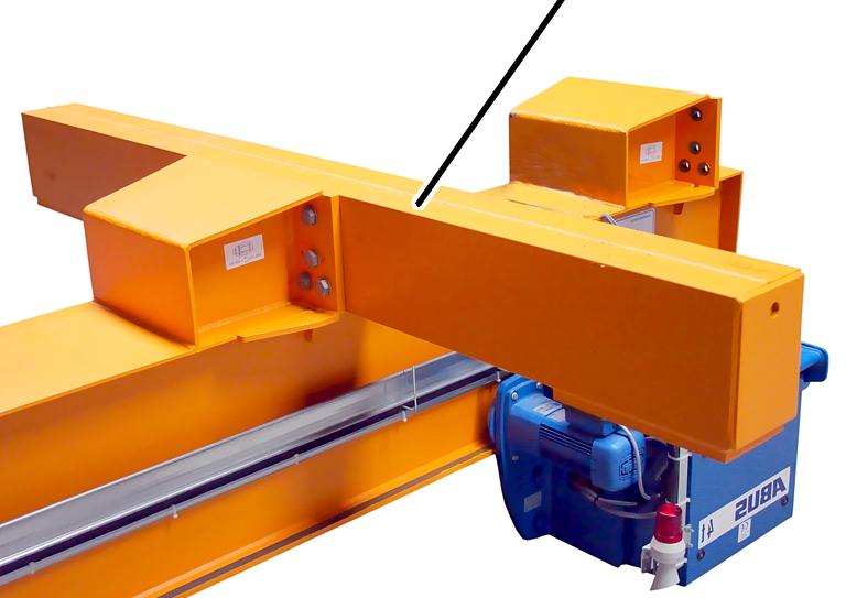
Inner cross head beam |
|
| |
─ Next, the inner cross head beam is mounted on the main girder. See ʺAssembling the inner cross head beam on the main girderʺ.
|
Inner cross head beam |
|
|
| |
|
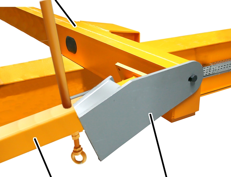
Diagonal braces |
Assembly joint |
─ Next, the diagonal braces of the previously prepared portal support are connected with an assembly joint to the inner cross head beam. See ʺConnecting the main girder to the portal supports (with assembly joint)ʺ.
|
|
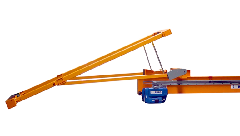
─ The semi-goliath crane lies stretched out on the floor.
|
|
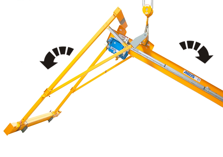
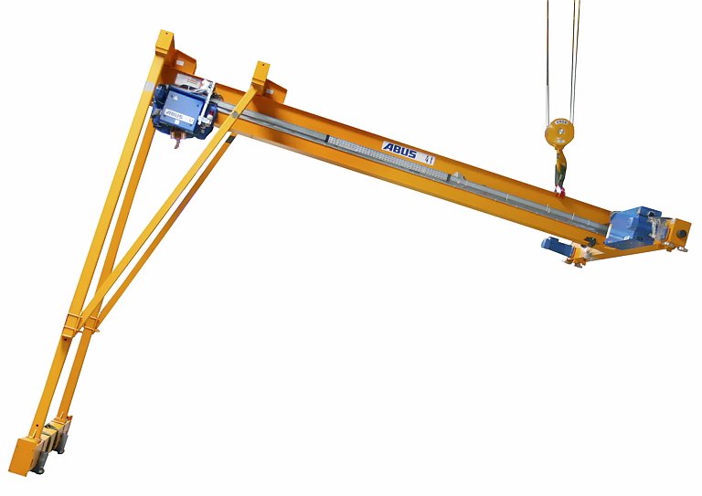
─ Finally, the crane is raised. The outer cross head beam swivels to the end of the main girder. See ʺTilting the portal supports to the main girderʺ.
─ The outer cross head beam is then connected with the main girder. See ʺBolting the tilted portal supports to the craneʺ.
─ The inner cross head beam is connected with the diagonal brace. See ʺBolting the tilted portal supports to the craneʺ.
─ The assembly joint and the assembly cross brace are removed. See ʺRemoving the assembly cross brace and assembly jointʺ.
|
|
─ The crane is raised on the other end and placed on the upper crane track. See ʺLifting the crane to the crane trackʺ.
─ Next, the assembly rollers are removed from under the end carriage. See ʺRemoving the assembly rollersʺ.
─ Additional individual parts (guard plates, lift-off prevention device, ...) are then installed on the crane. See ʺInstalling the individual parts on the craneʺ.
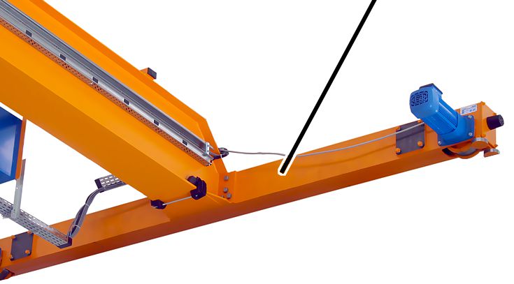
─ Next, the mains power supply is installed on the upper end carriage and connected. See ʺInstalling the mains power carrying fork (MCF)ʺ.
─ The lower end carriage is then aligned. See ʺAligning the craneʺ.
─ Next, the crane travel limit switch and/or anti-collision device is installed. See ʺInstalling the crane travel limit switchesʺ or ʺInstalling the anti-collision deviceʺ.
─ The light barriers of the obstacle detection sensor are then installed on the lower end carriage and connected. See ʺInstalling and connecting the obstacle detection sensorʺ.
─ Next, the signal lamp is installed on the A-frame and connected. See ʺInstalling and connecting the signal lampsʺ.
─ The danger zone of the crane is then defined. See ʺDefining the danger zone of the craneʺ.