Connection cables
Outer cross head beam
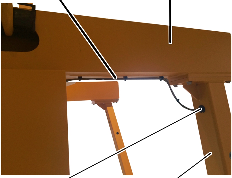
Cable bushing
A-frame
The light barriers of the obstacle detection sensor are installed in the front and back on the lower end carriage (two each per side). These serve in detecting obstacles in front of the end carriage and stopping the crane.
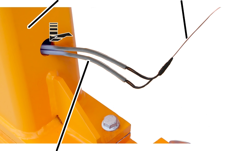
The connection cables for the signal lamp and light barriers of the obstacle detection sensor are pulled down through the A-frames from above by means of two draw wires. The connection cables for the light barriers and the signal lamp should be pulled simultaneously through the A-frame.
|
Connection cables |
Outer cross head beam |
|
| |
|
Cable bushing |
A-frame |
 Lay connection cables for
light barriers (2x) and signal lamp (1x) from the main girder along the outer
cross head beam to the A-frame.
Lay connection cables for
light barriers (2x) and signal lamp (1x) from the main girder along the outer
cross head beam to the A-frame.
Secure the connection
cables to the cable fasteners under the outer cross head beam using cable
ties.
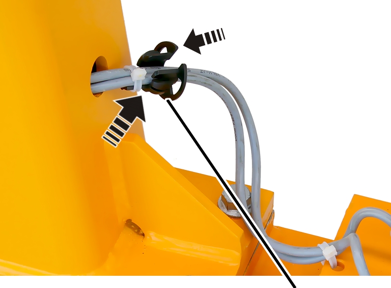
One of the two draw wires
leads to the bottom hole on the A-frame (hole directly on the lower end
carriage). Fasten the two connection cables for the two light barriers here.
The other of the two draw
wires leads to the centre hole on the A-frame (the hole which is at eye level in
the A-frame). Fasten the connection cable for the signal lamp here.
|
A-frame |
Draw wire |
|
| |
|
Connection cable |
|
Pull the two connection
cables for the light barriers through the A-frame using the draw wire.
|
| |
|
|
Cable bushing |
 Insert the cable bushing
on the connection cable.
Insert the cable bushing
on the connection cable.
Fix the cable bushing with
cable clips.
Insert the cable bushing
in the hole in the A-frame.
|
| |
|
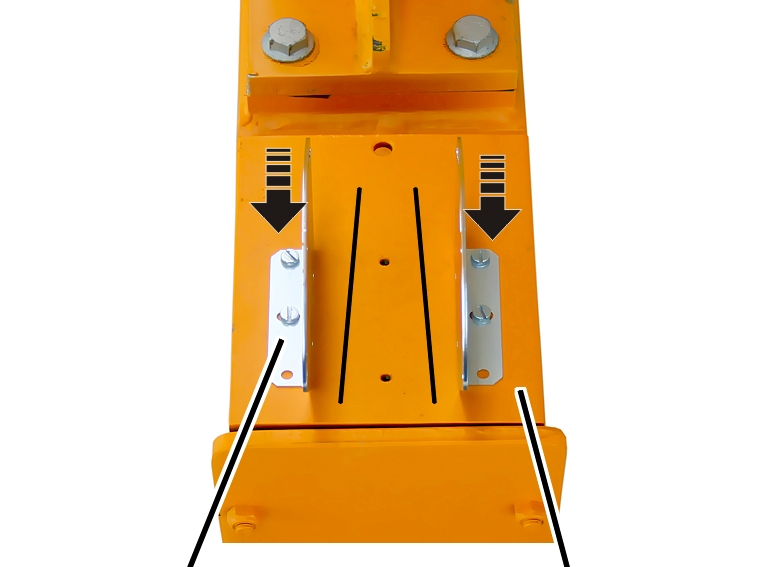
Mounting bracket |
Lower end carriage |
Position the two mounting
brackets on the lower end carriage as shown in the picture.
The mounting brackets should be positioned apart at a slight angle to the end of the end carriage.
Bolt on the mounting
brackets using the M6x10 fillister-head screws with S6 washers (2 per bracket)
in the outer screw holes. 5 Nm.
|
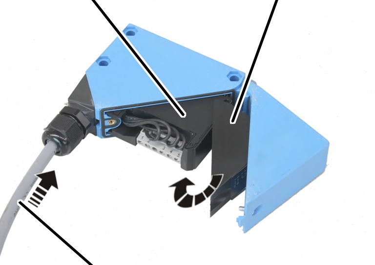
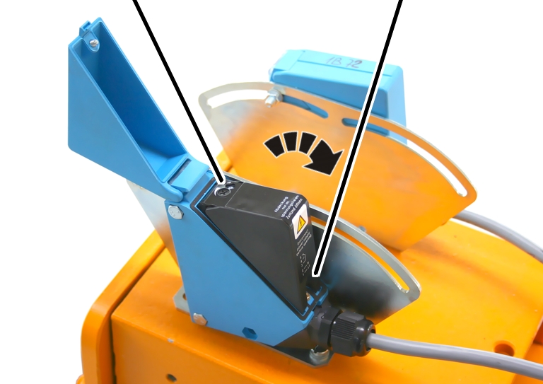
Light barrier |
Inner cover |
|
| |
|
Connection cable |
|
Lay the connection cable
in the light barrier and connect it.
Close the inner cover of
the light barrier.
|
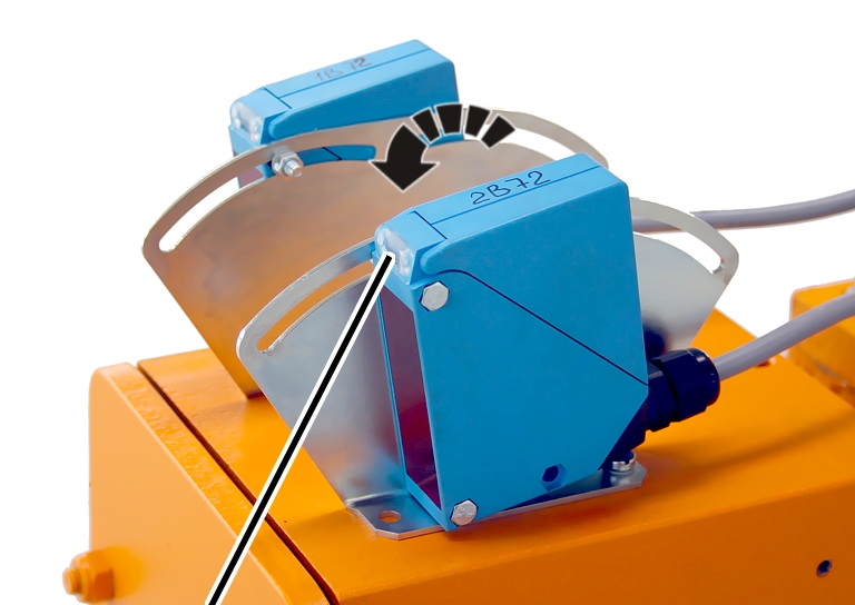
Light barrier |
|
|
| |
Attach the light barriers
to the mounting brackets as shown in the picture.
Bolt on the light barriers
using the M5x35 fillister-head screws with S5 washers and M5 hexagonal nut.
5 Nm.
The light barriers ensure the shut-down of the crane if an obstacle is present within the traversing range. The light barriers must be aligned so that the crane, even if under load at maximum capacity, is able to come to a timely stop when the light barrier detects an obstacle.
|
Additional 0.5 m |
Braking distance |
|
| |
|
Obstacle |
|
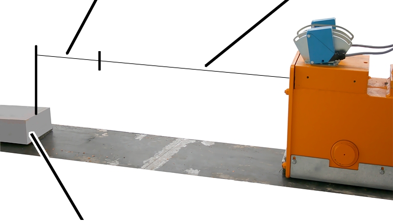
Determine the braking
distance of the crane (under load at maximum capacity).
Place an object that is as
dark, flat and wide as possible (e.g. dark wooden beams) in front of the lower
end carriage as an obstacle.
The object should be laid
so that it is at the braking distance in front of the lower end carriage.
Then move the object an
additional 0.5 m away from the end carriage (additional safety
clearance).
|
Adjustment control for the range |
Light barrier |
|
| |
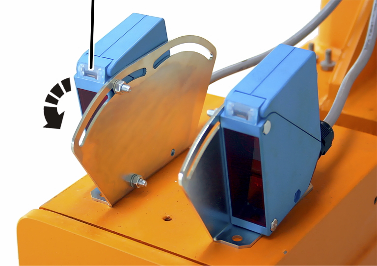
Set the range of the light
barrier to “max” on the adjustment control.
Tilt the light barrier
fully back until it is nearly horizontal.
|
| |
|
LED |
|
Slowly tilt the light
barrier forward until the LED lights up.
● The LED on the light barrier lights up. The light barrier has detected the object.
Slowly reduce the range of
the light barrier (turn adjustment control toward “min”) until the LED goes
dark.
● The range of the light barrier is now reduced so far that the light barrier no longer detects the object.
Slowly increase the range
of the light barrier (turn toward “max”) until the LED lights up.
● The range of the light barrier is now adjusted exactly for the object.
Set all other light
barriers in the same manner.
|
| |
|
Object |
|
Move the object back and
forth and observe the LED of the light barrier.
When the object is moved away from the crane, the LED on the light barrier must go dark. When the object is moved back toward the crane, the LED must light back up.
|
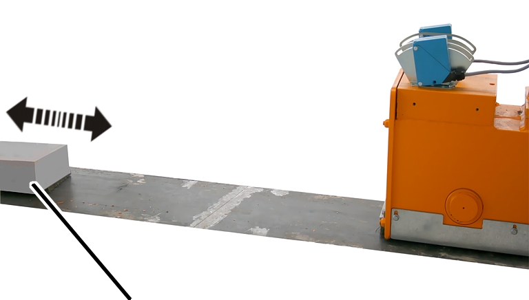
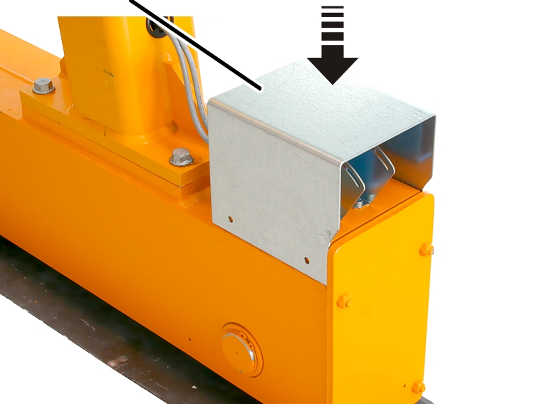
Guard plate |
|
|
| |
Attach the guard plate to
the lower end carriage.
Bolt on the guard plate
with M6x12 rib screws (4x for each guard plate). 19 Nm.