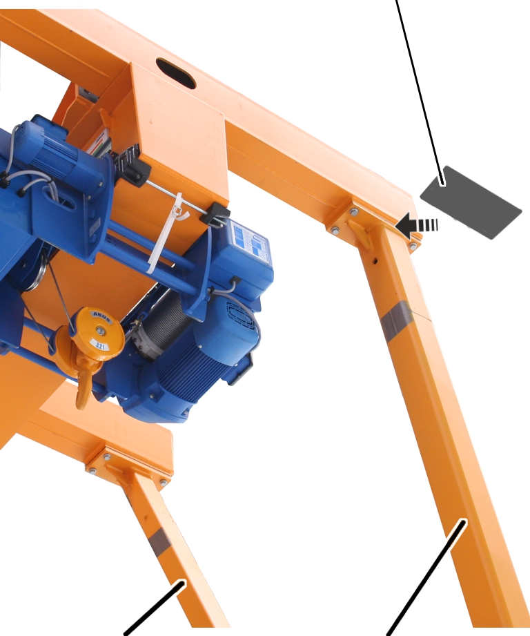
Move the crane forward and
back.
Move the crane forward and
back.
Once the crane is (temporarily) connected to the mains supply:
Move the crane forward and
back.
Check whether the lower
end carriage runs outside the track in either direction.
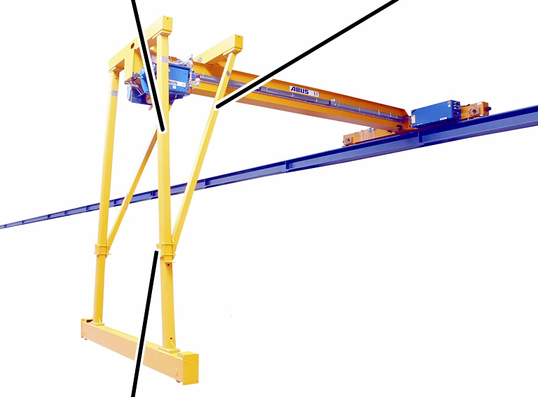
|
A-frame |
Diagonal brace |
|
| |
|
Screwed connection |
|
─ The screw connection between A-frame and diagonal brace has been aligned and bolted together by ABUS. It may not be altered.
─ Due to the camber of the main girder (main girder is curved upward slightly when not under load), the portal supports incline slightly inward (positive camber) in an unloaded state. When the crane lifts a load, the camber evens out and the portal supports stand vertically. The lower end carriage then shifts outward slightly.
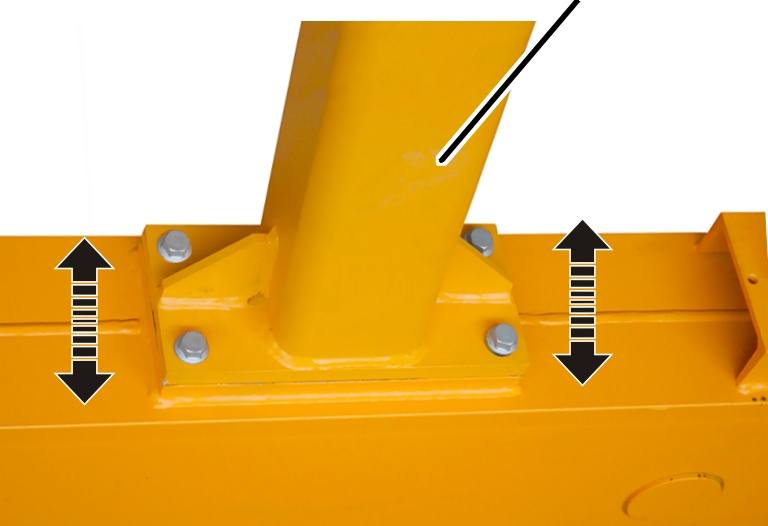
This section only applies if the supplied spacer plates (4x) need to be used for the alignment of the lower end carriage.
Increase the track gauge:
Insert the spacer plate
between the diagonal brace and the inner cross head beam.
Reduce the track gauge:
Insert the spacer plate
between the A-frame and the outer cross head beam.
|
|
Spacer plate |
|
| |
|
Diagonal brace |
A-frame |
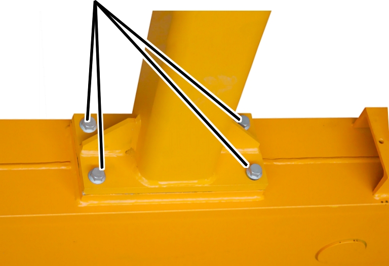
Release the M16x40 rib
screws (4x).
Insert the spacer plate
between the cross head beam and the diagonal brace or the A-frame.
A maximum of 2 spacer plates may be used per diagonal brace or A-frame!
Screw in the rib screws
M16x40 (4x).
|
|
A-frame |
|
| |
Slightly unscrew the rib
screws on the lower end carriage.
The rib screws were only temporarily tightened.
Move the end carriage
within the hole tolerance of the portal support to compensate for the deviation
in the track.
Repeat the test run.
|
Rib screws |
|
|
| |
 Bolt on the M16x40 rib
screws (4x each). 300 Nm.
Bolt on the M16x40 rib
screws (4x each). 300 Nm.
─ Only tighten rib screws with a suitable torque wrench.
─ Do not use an impact wrench.
─ Do not tighten rib screws using turn-of-nut tightening.