If available: Read the
position of the mains power carrying fork from the planning documents (drawing
“Installation position of mains power carrying fork (MCF)”).
If available: Read the
position of the mains power carrying fork from the planning documents (drawing
“Installation position of mains power carrying fork (MCF)”).
Depending on the type of crane and the on-site conditions in the building, the mains power supply is installed differently.
If available: Read the
position of the mains power carrying fork from the planning documents (drawing
“Installation position of mains power carrying fork (MCF)”).
 Additionally: Select the
installation version required at the site from the following versions and the
scope of delivery.
Additionally: Select the
installation version required at the site from the following versions and the
scope of delivery.
Installation versions for a suspended panel:
|
|
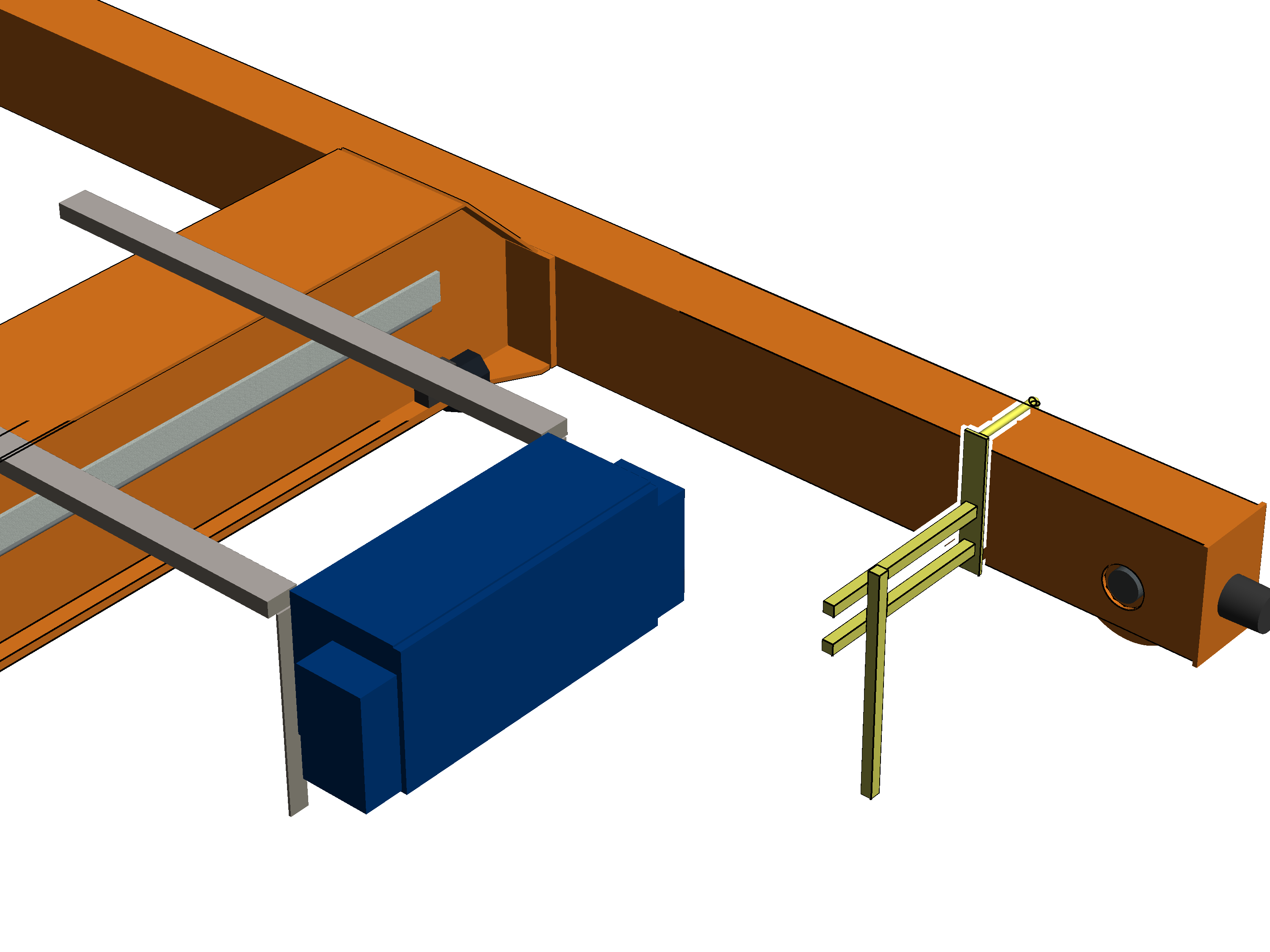
Preferred version: mains power carrying fork on the end carriage next to the panel
─ This preferred version can be used in most cases.
─ The mains power carrying fork consists of a single mount.
Whether the mains power carrying fork consists of one or two mounts is determined by the scope of delivery.
─ If the vertical square tube is 80 cm long, a single square tube is used.
If the vertical square tube is 100 cm or 130 cm long, two square tubes are used.
─ The mains power carrying fork must be installed inside as far as possible but still pose no risk of colliding with the trolley.
|
|
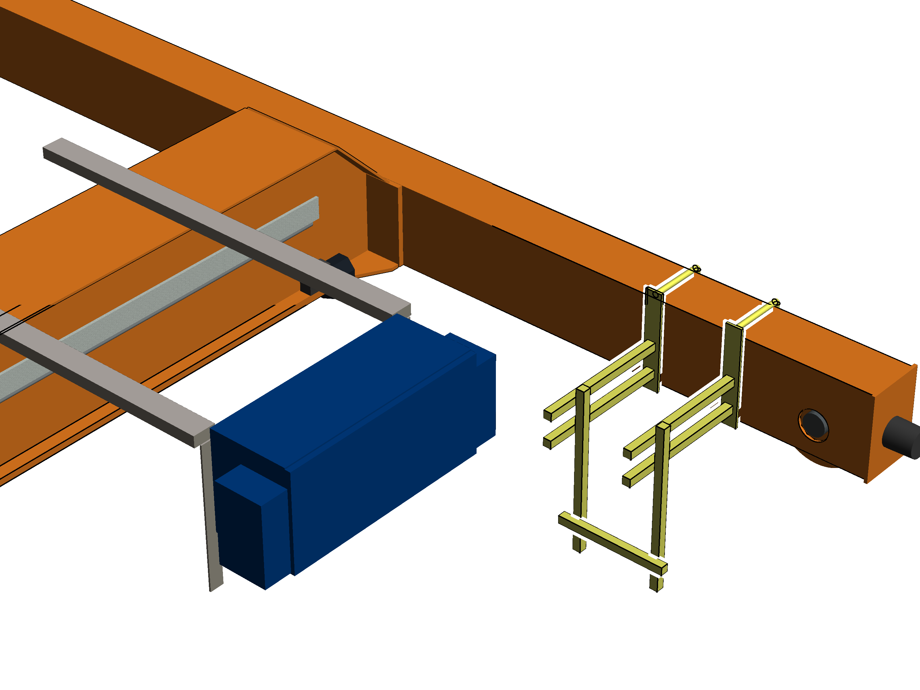
Next possible version: mains power carrying fork with dual mount on the end carriage
─ This preferred version can be used in most cases.
─ The mains power carrying fork consists of two mounts.
Whether the mains power carrying fork consists of one or two mounts is determined by the scope of delivery.
─ If the vertical square tube is 80 cm long, a single square tube is used on each mount.
If the vertical square tube is 100 cm or 130 cm long, two square tubes are used on each mount.
With 130 cm long vertical square tubes, the vertical square tubes of both mounts are additionally connected with each other crosswise by means of a square tube.
─ The mains power carrying fork must be installed inside as far as possible but still pose no risk of colliding with the trolley.
|
|
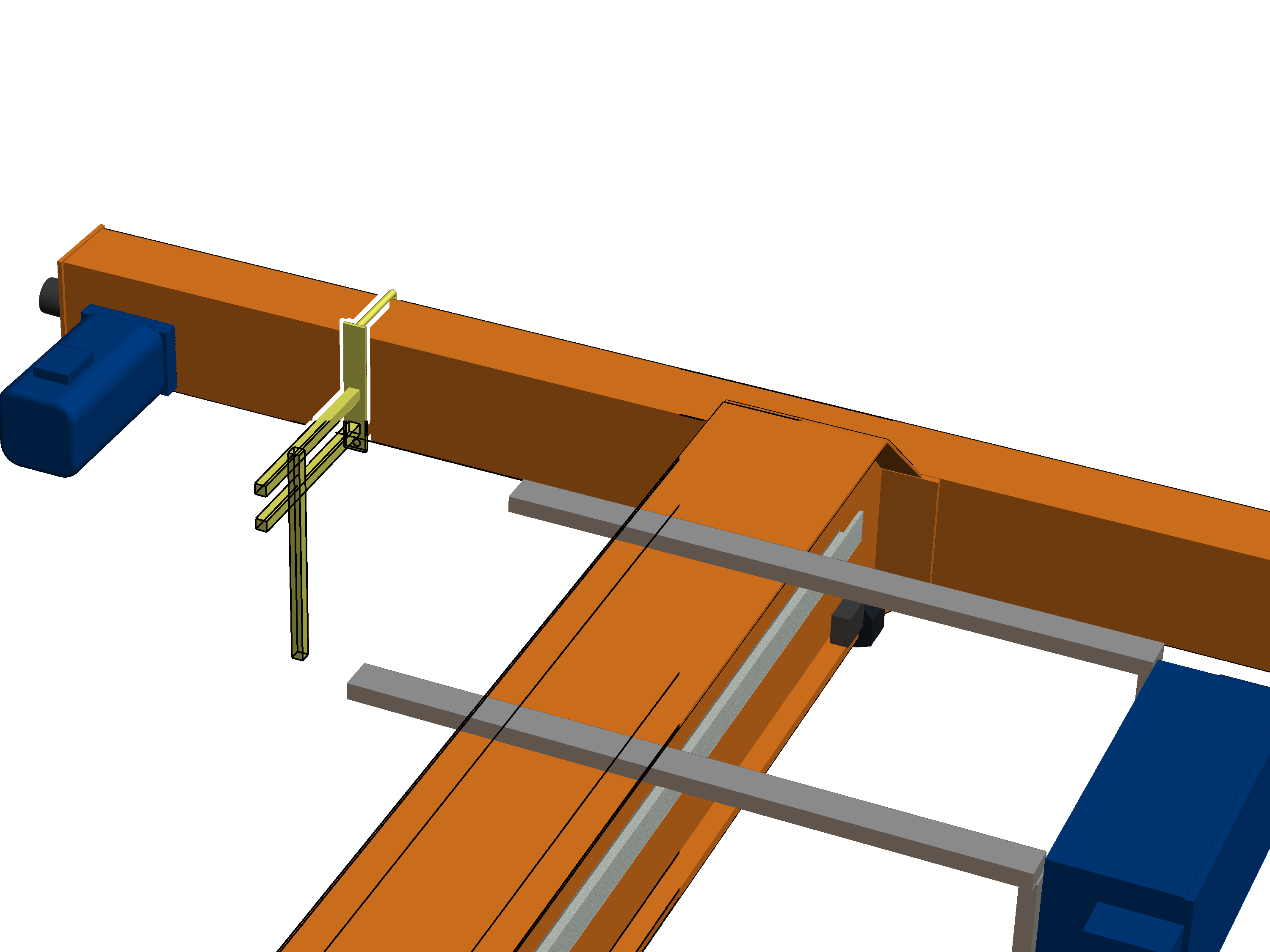
Next possible version: mains power carrying fork on the other side of the panel on the end carriage
─ This version can be used if there is insufficient space on the right side of the end carriage next to the panel (previous versions). Normally however, the clearance to the left and right next to the end carriage is identical on a crane with suspended panel.
─ The mains power carrying fork consists of a single mount.
Whether the mains power carrying fork consists of one or two mounts is determined by the scope of delivery.
─ The mains power carrying fork must be installed inside as far as possible but still pose no risk of colliding with the trolley.
─ If the connection cable of the current collector is not long enough, an additional terminal box must be installed and the connection cable extended.
─ If the vertical square tube is 80 cm long, a single square tube is used.
If the vertical square tube is 100 cm or 130 cm long, two square tubes are used.
|
|
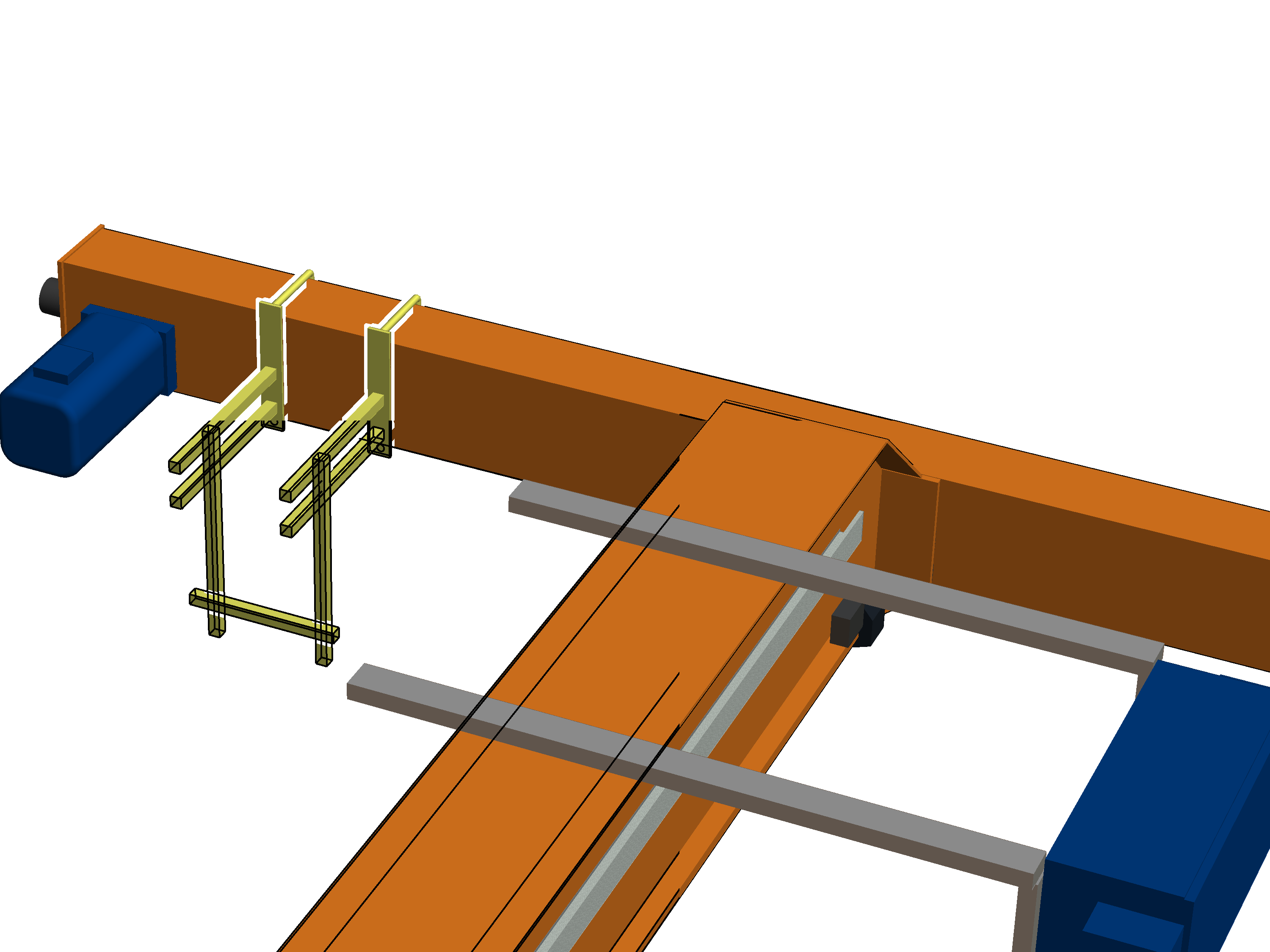
Next possible version: mains power carrying fork with dual mount on the other side of the panel on the end carriage
─ This version can be used if there is insufficient space on the right side of the end carriage next to the panel (previous versions). Normally however, the clearance to the left and right next to the end carriage is identical on a crane with suspended panel.
─ The mains power carrying fork consists of two mounts. Whether the mains power carrying fork consists of one or two mounts is determined by the scope of delivery.
─ The mains power carrying fork must be installed inside as far as possible but still pose no risk of colliding with the trolley.
─ If the connection cable of the current collector is not long enough, an additional terminal box must be installed and the connection cable extended.
─ If the vertical square tube is 80 cm long, a single square tube is used on each mount.
If the vertical square tube is 100 cm or 130 cm long, two square tubes are used on each mount.
With 130 cm long vertical square tubes, the vertical square tubes of both mounts are additionally connected with each other crosswise by means of a square tube.
One or two mounts are now assembled on the left or right of the end carriage, according to the previously selected installation version.
If necessary:
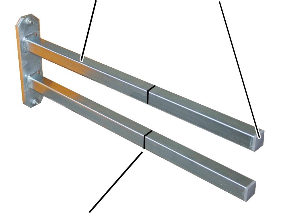
|
Mount |
Ribbed end cap |
|
| |
|
Shorten mount to required length |
|
Remove the ribbed end caps
(2x) from the mount.
Shorten the mount.
The required length is determined by the on-site conditions in the building and the safety clearances from the crane drawing.
Reinsert the ribbed end
caps (2x) into the ends of the mount.
|
| ||
|
| ||
|
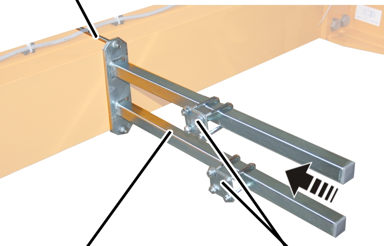
Mount |
Pipe clamp | |
Attach the mount to the end carriage on which
the crane panel is installed.
Bolt the mount onto the threaded bracket.
|
Threaded bracket |
Tightening torque |
|
M8 |
25 Nm |
|
M10 |
50 Nm |
|
M12 |
75 Nm |
Slide on the two pipe
clamps and secure them.
If necessary:
Remove the ribbed end cap
from the square tube.
Shorten the square tube.
Reinsert the ribbed end
cap into the square tube.
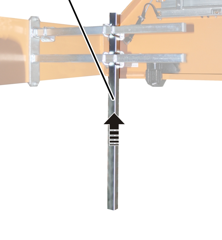
|
Vertical square tube |
|
|
| |
Move the vertical square tube to the required
position on the mount.
The required length is determined by the on-site conditions in the building and the safety clearances from the crane drawing.
Screw the vertical square
tube onto the mount using pipe clamps (2x). Tighten to 15 Nm.
For more than one vertical square tube:
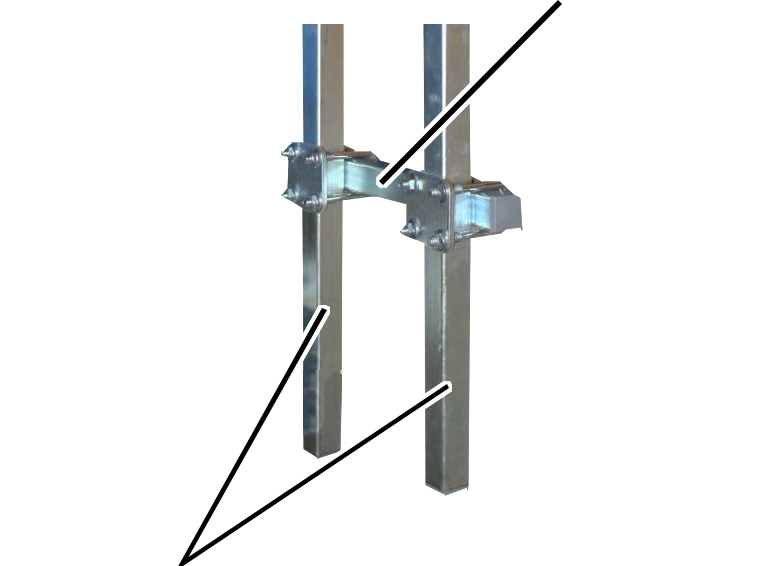
|
|
Horizontal square tube |
|
| |
|
Vertical square tube |
|
Attach the horizontal square tube with two pipe
clamps to the vertical square tubes.
The horizontal square tube can be a single square tube or a part of the current collector on the mains power supply.
Tighten the pipe clamps
(2x). 15 Nm
The required components are now installed on the prepared mains power carrying fork.
─ Current collector of the mains power supply.
─ Cross-type limit switch. See Installing the cross-type limit switch.
─ Red signal lamp
This section is only applicable if the overhead travelling crane has a cross-type limit switch in the direction of crane travel.
Where and for which travel limit the cross-type limit switch is designed is specified on the wiring diagram.
|
|
Danger due to malfunction! If the cross-type limit switch is screwed on too tightly, the parts on the inside can become jammed and no longer function properly. The tightening torque of 3 Nm must be precisely observed. |
|
Threaded bracket | |
|
| |
|
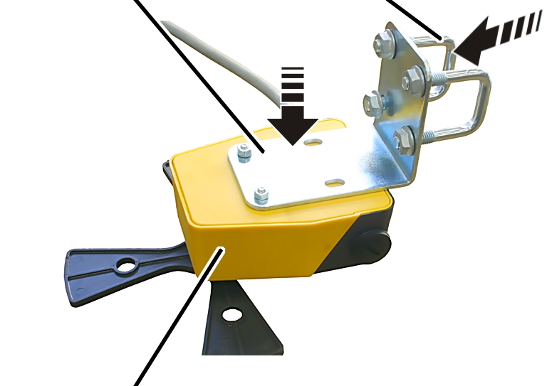
Cross-type limit switch |
|
Screw the mounting bracket
onto the cross-type limit switch with the fillister-head screws M5x50 (2x).
Screw on the mounting
bracket using locking washers and M5 hex nuts (2x). 3 Nm.
Insert threaded brackets
(2x) in the mounting bracket.
Loosely screw in the M8
rib nuts (4x).
The cross-type limit switch can be installed on the mains power carrying fork, for example.
|
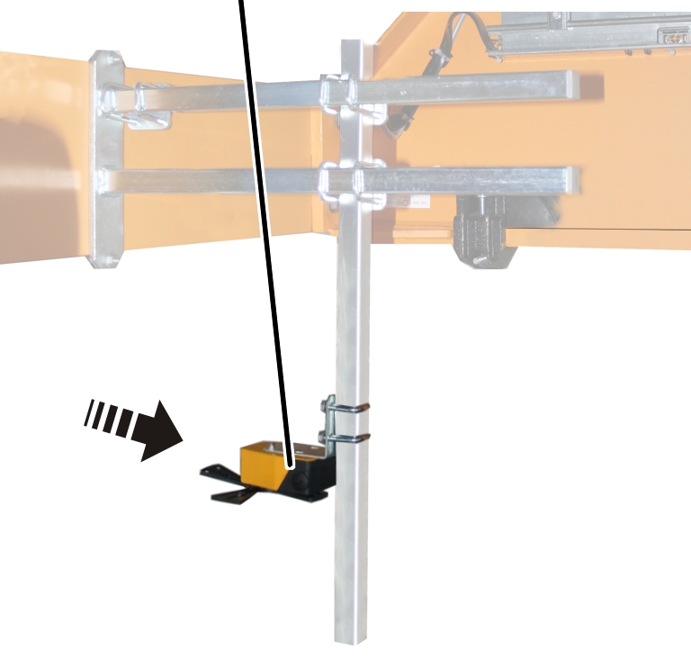
Crane travel limit switches |
|
|
| |
Turn the travel limit switch to
position 0.
The position of the cross-type limit switch is marked with an arrow that can be rotated further, depending on the switching state.
Hold the travel limit
switch against the square tube so that the switching lug activates the travel
limit switch.
Screw the travel limit
switch onto the vertical square tube using pipe clamps (2x). 15 Nm
Route the connection cable
(round cable or flat cable) from the cross-type limit switch to the panel.
Route the connection cable
with cable fitting into the panel.
If necessary: Connect the
connection cable to a coupler plug or connector.
Fasten the connection
cable with cable ties, cable ducting and adhesive clips.
|
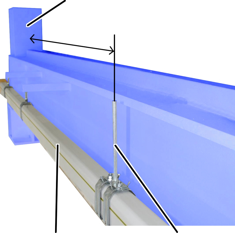
End stopper |
|
|
| |
|
Conductor system |
Actuating cam |
Suspend a load on the load
hook which corresponds to the maximum load capacity of the crane.
Determine the necessary
distance between the actuating cam and the end stopper:
For braking function: The distance must be such that the crane is only travelling at a low speed shortly before the end stopper.
For shut-down: The distance must be such that the crane is at a standstill shortly before the end stopper.
Install the actuating cam
for the crane travel limit switch to the crane track or conductor system at the
determined distance.