
AT A GLANCE:
General information
Applies to anyone who uses the crane or works nearby
At the start
Using this product manual
The following symbols are used in this product manual:
- This is an instruction regarding an action and prompts you to perform a work step.
- This is the result of an action and describes what happens on the device.
- This is a list.
Only with...
A section that appears in a box framed by a dashed line is only applicable for certain types, versions or options. The condition to which the section applies is specified at the beginning in the heading “Only with...”.
Instructions for the product manual
Read the product manual through carefully before beginning work. Also be sure to observe additional product manuals for accessories and components.
Afterwards, keep the product manual available in the vicinity of the crane. It must be accessible to all who work with or on the crane.
In the case of reselling or hiring out, always provide the product manual together with the crane.
Note regarding the designation “crane”
The term “crane” as used in all product manuals refers to every ABUS product with which a load can be lifted and/or transported.
The term “crane” also refers to all overhead travelling cranes, jib cranes, HB cranes and other cranes including trolley (with wire rope hoist or chain hoist). Solo wire rope hoists and solo chain hoists are also referred to as “crane”.
Printing out product manuals or making them available per computer
The product manuals belonging to this crane are available on the enclosed data carrier as files in PDF format. Some of these product manuals may also be enclosed in printed format in the documentation folder of the crane.
All supplied product manuals (on data carrier or printed) must be made continually available to all persons working with or on the crane.
- Print out all product manuals supplied on the data carrier and store them near the crane. Keep the product manuals in a place accessible to all persons who work with or on the crane.
- Alternatively, make all product manuals supplied on the data carrier available per computer. In doing so, make sure the computer is able to display the PDF files and is always operational, and that all persons who work with or on the crane can access this computer.
- Keep the product manual “Operating the ABUS crane” available in the vicinity of the crane. This product manual contains important information for the crane operator and should be within easy reach at all times.
Proper use
The crane is designed for the lifting and lowering of correctly attached loads and, depending on design, moving them as well.
ABUS cranes are designed for these applications:
- Overhead travelling crane for all-round moving of loads.
- Jib crane for moving loads in a circular direction.
- HB crane for all-round moving of lightweight loads.
- Single-rail trolley track for moving loads in a linear direction.
- Mobile gantry crane for location-independent all-round moving of lightweight loads.
- Solo chain hoist and solo wire rope hoist for the stationary lifting and lowering of loads.
- During operation, observe the classification according to FEM, duty cycle and switching rate. See the product manual “Operating the ABUS crane”.
- Only operate the hoist if the actual hours of use are fewer than the number of hours representing the theoretical service life.
- Only use the crane in chemically non-aggressive environments that pose no risk of explosion.
- Long-term usage of the crane only in weatherproof areas. Temporary use in unprotected environments (outdoors in rain, snow or cold weather) is permitted. For longer operation in unprotected environments, modifications must be made to the crane. See “Equipping the crane for operation in unprotected environments”.
In windy environments, even short-term use is prohibited. If the crane is to be used in windy conditions, modifications must be made to the crane. See “Equipping the crane for operation in unprotected environments”.
Regulations
The installation has been built and tested according to European standards, rules and regulations applicable at the time of its manufacture. The conventions applied during design and construction are specified in the Declaration of Conformity or the Declaration of Incorporation. The conventions must also be observed for installation, operation, inspection and maintenance, as must the applicable occupational health and safety regulations.
Which provision applies in individual cases will greatly depend on the crane’s use and the national regulations. Review and observe all applicable and current regulations, including the occupational health and safety regulations. Refer also to the Declaration of Conformity or Declaration of Incorporation.
This product manual is based on the regulations and directives applicable in Germany and the European Union.
If the crane is operated in a different country, the instructions given in this product manual still apply. They then supplement the national regulations. The content specified in the product manuals should then be considered the minimum requirements which must be met in any case. The national regulations supplement these requirements, but do not reduce them.
Exception: If the national regulations represent an explicit contradiction to the contents of the product manual, the national regulations have priority.
Warranty
- ABUS assumes no liability for damages that were caused by improper use, inadequately trained personnel, incorrect performance of work, nor for any changes, reconstruction or other modification of the crane or crane components which were not approved by ABUS.
- Any warranty claim becomes invalid if components were modified without consent, the crane or crane components were installed, used or serviced in any way other than that described in this product manual, or if parts other than original ABUS replacement parts were used.
- Safe operation of the crane or crane components is only guaranteed if original ABUS replacement parts are used.
Preparing a risk assessment
In connection with the crane, dangerous situations can arise in all operating modes (during operation, at a standstill, during maintenance work) and in all product phases.
Why, when and where these hazards occur as well as who causes them and how, depends on a great number of different conditions. Among these are the application area of the crane, the conditions and work routine within the building, the interaction with other machines, etc.
The hazards described in this and all other product manuals refer to the standard applications of the crane and especially cover the dangers arising directly from the crane itself.
In order to take all other arising hazards into account, the end user must create a risk assessment and factor in all possible risks in all modes of operation.
Special transport tasks, such as transport using two trolleys, tandem operation, turning of loads or similar, pose additional risks and must be additionally taken into account.
The end user must then undertake the appropriate measures and precautions to minimise or eliminate these risks.
The end user is responsible for the risk assessment and the implementation of appropriate countermeasures.
Instructions regarding safety: For anyone, who performs work with or on the crane, or works nearby
Observe these instructions for safe handling of the crane. Special hazard notices are located in the corresponding sections in which the danger arises.
These instructions specify basic dangers that can arise from the crane. Additional dangers must be determined through a risk assessment and then eliminated.
Instructions regarding safety: For the end user of the crane
Follow these instructions to ensure employees use the crane safely.
Only with cranes with overlapping operating ranges
Only with tandem operation
The crane
This section provides a rough overview of the ABUS product range. Other combinations of cranes and trolleys are possible. Additional types of cranes and trolleys are also available.
Description of the
single-girder travelling crane
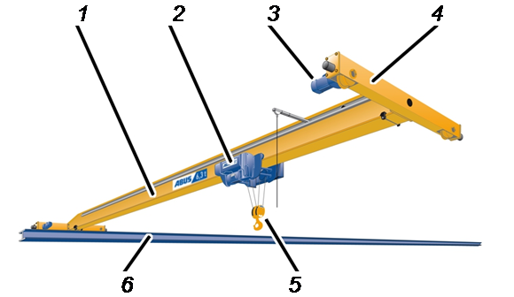
- 1: Main girder (ELV version)
- 2: Trolley (wire rope hoist or chain hoist)
- 3: Crane travel drive
- 4: End carriage
- 5: Bottom block and load hook
- 6: Crane track
Description of the
double-girder travelling crane
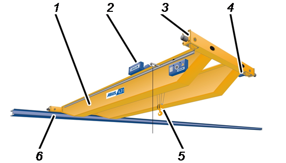
- 1: Main girder
- 2: Trolley (wire rope hoist)
- 3: End carriage
- 4: Crane travel drive
- 5: Bottom block and load hook
- 6: Crane track
Description of the
underslung travelling crane
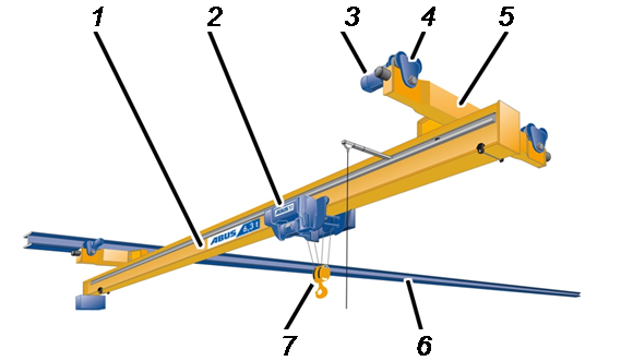
- 1: Main girder
- 2: Trolley (wire rope hoist or chain hoist)
- 3: Crane travel drive
- 4: Crane trolley
- 5: End carriage
- 6: Crane track
- 7: Bottom block and load hook
Description of the device
Wall travelling crane
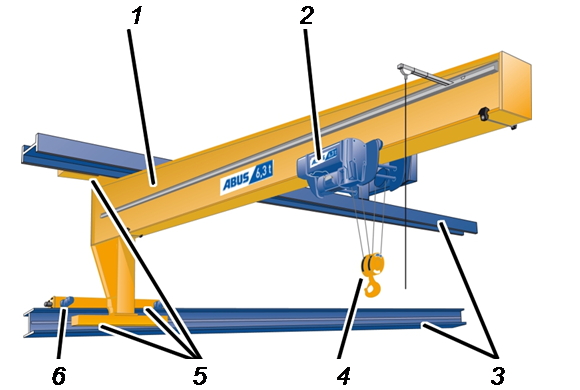
- 1: Main girder
- 2: Trolley (wire rope hoist or chain hoist)
- 3: Crane track
- 4: Bottom block and load hook
- 5: End carriage
- 6: Crane travel drive
Description of the
semi-goliath crane
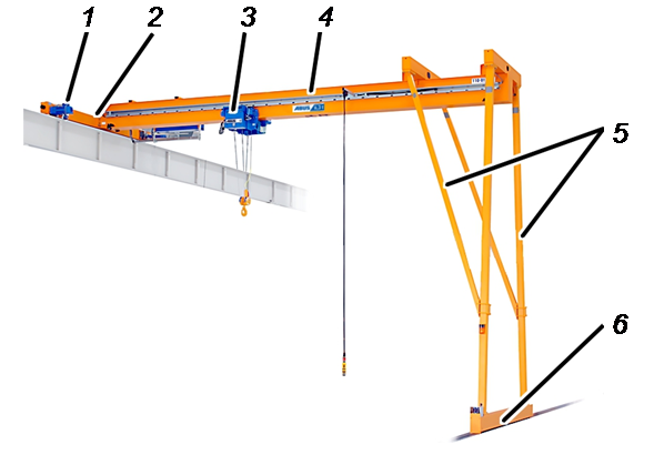
- 1: Crane travel drive
- 2: Upper end carriage
- 3: Trolley (wire rope hoist)
- 4: Main girder
- 5: Portal support
- 6: Lower end carriage
Description of the
pillar slewing jib crane
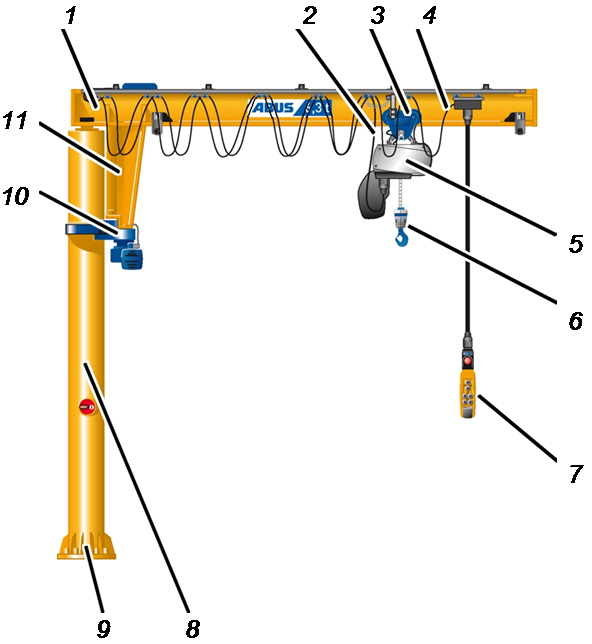
- 1: Jib arm
- 2: Trolley power supply
- 3: Hoist trolley
- 4: Mobile control (optional)
- 5: Trolley (wire rope hoist or chain hoist)
- 6: Load hook
- 7: Pendant control
- 8: Pillar
- 9: Pillar base
- 10: Slewing gear unit
- 11: Jib bracket
Description of the
wall jib crane
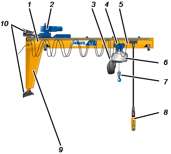
- 1: Jib arm
- 2: Slewing gear unit
- 3: Trolley power supply
- 4: Hoist trolley
- 5: Mobile control (optional)
- 6: Trolley (wire rope hoist or chain hoist)
- 7: Load hook
- 8: Pendant control
- 9: Jib bracket
- 10: Wall mounts
Description of the
HB crane monorail system
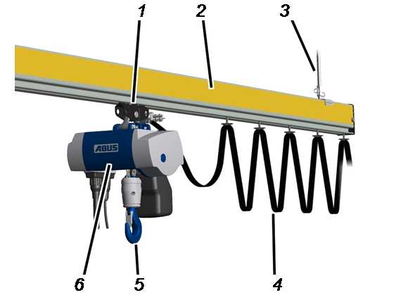
- 1: Suspension
- 2: Trolley track
- 3: Hoist trolley
- 4: Trolley power supply
- 5: Load hook
- 6: Trolley (chain hoist)
Description of the
HB crane type single-girder crane
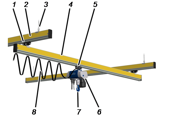
- 1: Crane trolley
- 2: Crane track
- 3: Suspension
- 4: Crane girder
- 5: Hoist trolley
- 6: Trolley (chain hoist)
- 7: Load hook
- 8: Trolley power supply
Description of the
single-rail trolley track
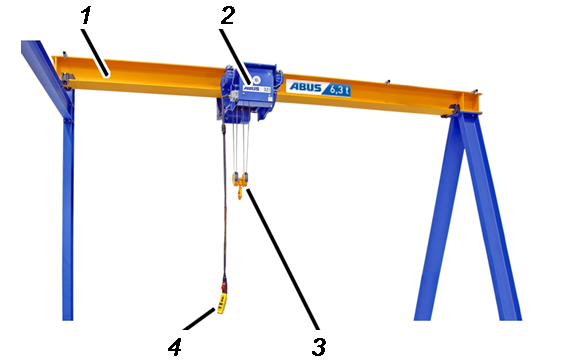
- 1: Trolley track
- 2: Trolley (wire rope hoist or chain hoist)
- 3: Bottom block and load hook
- 4: Pendant control
Description of the
mobile gantry crane
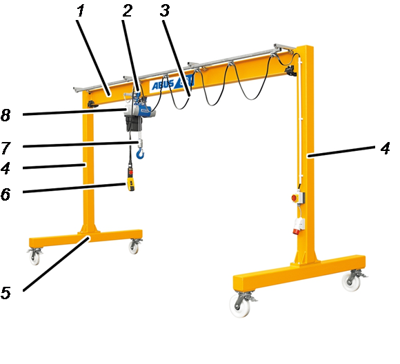
- 1: Main girder
- 2: Hoist trolley
- 3: Trolley power supply
- 4: Portal support
- 5: End carriage
- 6: Pendant control
- 7: Load hook
- 8: Trolley (chain hoist)
Description of the
solo chain hoist
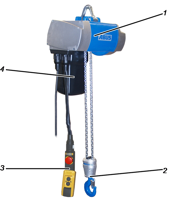
- 1: Housing
- 2: Bottom block and load hook
- 3: Pendant control
- 4. Chain box
Description of the device
Single-rail trolley
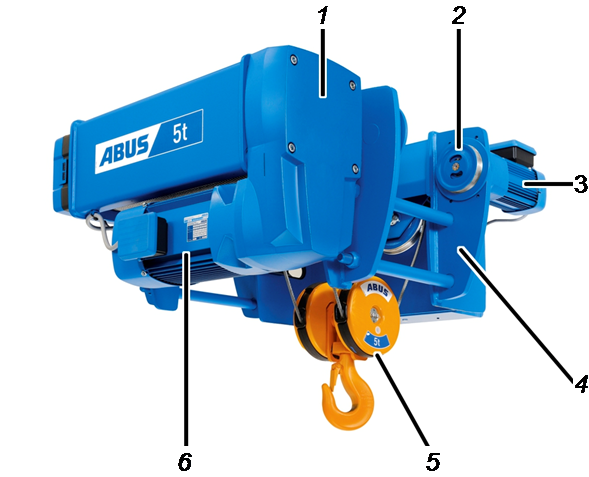
- 1: Hoisting gear
- 2: Hoist trolley
- 3: Trolley drive
- 4: Trolley frame
- 5: Bottom block and load hook
- 6: Hoist motor
Description of the device
Side-mounted trolley
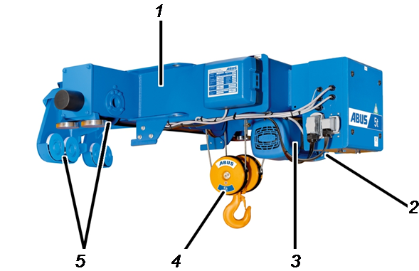
- 1: Trolley frame
- 2: Hoisting gear
- 3: Hoist motor
- 4: Bottom block and load hook
- 5: Hoist trolley
Description of the device
Double-rail trolley
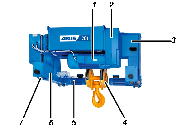
- 1: Hoist motor
- 2: Hoisting gear
- 3: Trolley frame
- 4: Bottom block and load hook
- 5: Trolley drive
- 6: End carriage
- 7: Hoist trolley
Device description of lower flange trolley
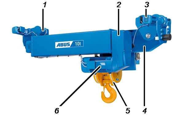
- 1: Hoist trolley
- 2: Hoisting gear
- 3: Trolley drive
- 4: Trolley frame
- 5: Bottom block and load hook
- 6: Hoist motor
Performance features
The single- and double-girder travelling crane and the underslung travelling crane:
- The cranes are designed for all-round moving of loads in a building or within a section of a building.
- The crane travels on a crane track, which is fastened to building supports or concrete supports beneath the hall ceiling or on a separate supporting structure.
- The cranes have a wire rope hoist or a chain hoist with a manually driven or electric trolley (HF/EF).
The wall travelling crane:
- The crane is designed for all-round moving of loads within the operating range on a building wall.
- The crane travels on a crane track, which is fastened laterally to building supports or concrete supports.
- The crane has a wire rope hoist or a chain hoist with a manually driven or electric trolley (push trolley/electric trolley).
The semi-goliath crane:
- The crane is designed for all-round moving of loads within the operating range on a building wall.
- The semi-goliath crane travels on the building wall with the upper end carriage on a crane track. It runs to the middle of the building with the lower end carriage on the floor of the building.
- The crane has a wire rope hoist as a trolley.
The pillar slewing jib crane:
- The crane is designed for the moving of loads in a circular direction or arc within the operating range around the crane pillar.
- The crane pillar is fixedly anchored to the floor of the building or a foundation specially created for it.
- The crane has a wire rope hoist or a chain hoist with a manually driven or electric trolley (push trolley/electric trolley), depending on type.
The wall jib crane:
- The crane is designed for the moving of loads in an arc within the operating range around the wall mounting.
- The crane is fixedly anchored to the building wall, building support, or a concrete support.
- The crane has a wire rope hoist or a chain hoist with a manually driven or electric trolley (push trolley/electric trolley), depending on type.
The HB crane:
- The HB single-girder and double-girder cranes are designed for all-round moving of lightweight loads within the operating range.
- The monorail and double-rail systems are designed for moving lightweight loads in a linear direction.
- The cranes are suspended from HB crane runways, which are fastened under the hall ceiling or on a separate supporting structure.
- The crane has a chain hoist as a trolley.
The single-rail trolley track:
- The crane is designed for moving loads in a linear direction within the operating range.
- The crane track is fastened to the building wall, on building supports, concrete supports, or on a separate supporting structure.
- The crane has a wire rope hoist or a chain hoist with a manually driven or electric trolley (push trolley/electric trolley).
The mobile gantry crane:
- The crane is designed for moving lighter loads exclusively within the direct environment of the operating range.
- The crane can be used flexibly in different operating ranges independently of the location.
- The crane runs on four castors, freely movable on level ground.
- The crane has a chain hoist as a trolley.
The solo chain hoist:
- The solo chain hoist is designed for the stationary lifting and lowering of loads.
- It is stationary and fastened to an appropriately dimensioned supporting structure.
The single-rail trolley:
- The wire rope hoist serves as a trolley on single-girder travelling cranes.
- The wire rope hoist has a hoist trolley with which it travels along the lower flange of the main girder.
The side-mounted trolley:
- The wire rope hoist serves as a side-mounted trolley on single-girder travelling cranes.
- The wire rope hoist has a two-part hoist trolley. One part is used to run the wire rope hoist along the trolley track, which is mounted on the side of the main girder. The load hook hangs from the side of the main girder on which the trolley track is mounted. On the other side of the main girder, the other part of the hoist trolley grips onto the upper flange.
The double-rail trolley:
- The wire rope hoist serves as a trolley on double-girder travelling cranes.
- The wire rope hoist has two end carriages with which it travels along the trolley track of the main girder.
The lower flange trolley:
- The wire rope hoist serves as a trolley on single-girder travelling cranes.
- The wire rope hoist has hoist trolleys with which it travels along the lower flange of the main girder.
Technical data
Normal ambient conditions during operation:
Range |
|
|---|---|
Ambient temperature |
-10 °C to +40 °C |
Height position |
Up to 1000 m above sea level |
Operation in other ambient conditions (e.g. at a higher ambient temperature) is in many cases possible. For questions regarding individual on-site conditions in the building (e.g. duration and type of heat and its influence on the crane), ABUS Service will gladly be of assistance. See “ABUS Service”.
Only with travel drives and hoist drives
This section only applies to travel drives and hoist drives.
Range |
||
|---|---|---|
Ambient temperature |
-10 °C to +40 °C |
|
Ambient temperature (for reduced duty cycle) |
+40 °C to +65 °C |
|
Ambient conditions exclusively for travel and hoist drives.
Travel and hoist drives can also be used at a reduced duty cycle and switching rate, even at an ambient temperature of +40°C to +65°C.
Operation at higher ambient temperatures:
Duty cycle according to type plate |
Modified duty cycle at ambient temperatures of |
|---|---|
60 % |
30 % |
50 % |
25 % |
40 % |
20 % |
Switching rate according to type plate |
Modified switching rate at ambient temperatures of |
|---|---|
420 |
210 |
360 |
180 |
300 |
150 |
240 |
120 |
180 |
90 |
- At ambient temperatures of +40°C to +65°C, reduce the duty cycle and switching rate according to the tables.
Operation at higher elevations:
At higher elevations, the crane will be less well cooled due to the reduced air pressure.
- Reduce the duty cycle and switching rate at higher elevations.
Mechanical design life
The mechanical design life of the crane is 20 to 25 years.
Storage of the crane
If the crane is not installed immediately:

- Wipe off any rainwater.
- Cover unpainted surfaces and openings with film and mask it.
- Unpack components wrapped in film (e.g. pillars and jib arms from the jib crane). Otherwise, condensation collects under the film.
- Store unpainted metallic parts, wire rope hoists, chain hoists, electrical and electronic components in a dry, dust-free place.
- Store painted metallic parts as dry and dust-free as possible.
Inspection after lengthier storage
Should the crane be installed after it has been in storage for a lengthier period:
- Perform a visual inspection of all components. They should be neither heavily soiled nor dusty.
- Inspect the paintwork. The paint should not be cracked or peeling.
- Inspect metallic parts. They should exhibit no rust.
- Inspect electrical components. Live parts (e.g. bushes, pins and terminals) should not be oxidised (e.g. discoloured or roughened surface).
Installing and connecting
This section applies to anyone who works on the crane prior to its use
The end user of the crane is responsible for the proper qualifications of the commissioning personnel.
Examples of qualified persons:
- Persons with comprehensive knowledge from specialist training in engineering and in the electrical systems of cranes.
- Persons with sufficient experience in the operation, installation and maintenance of cranes.
- Persons with comprehensive knowledge regarding the relevant technical rules, directives and safety regulations applicable in the respective country.
- Persons receiving regular training from ABUS.
ABUS assumes no liability for damage due to incorrectly performed commissioning work done by unqualified personnel.
ABUS recommends having the commissioning work performed by the ABUS assembly team.
Instructions regarding safety: Before putting into operation
Comply with the following safety instructions before beginning with putting the crane into operation:
Instructions regarding safety: When putting into operation
Comply with the following safety instructions when putting the crane into operation:
Instructions regarding safety: After putting into operation
Comply with the following safety instructions once putting into operation has been completed:
Installation overview
For assembly of an entire crane installation:
- In all supplied product manuals, read the sections “Installation overview” and “Checking the requirements”.
- First fulfil the requirements in the building (e.g. for overhead travelling cranes, install the crane track; for jib cranes, prepare the foundation,...).
- Then, depending on the individual components, define the order of the installation work.
- Finally, follow the respective sections for “Installing” in all product manuals according to the defined order to assemble the crane.
- If necessary: Protect the crane from rain, snow, wind or cold. See “Equipping the crane for operation in unprotected environments”.
- Next, connect the crane to the mains supply. See “Connecting the crane to the mains supply”.
- Finally, carry out the test before initial commissioning. See “Test before initial commissioning”.
Equipping the crane for operation in unprotected environments
Only with overhead travelling cranes
Long-term usage of the crane only in weatherproof areas. Temporary use in unprotected environments (outdoors in rain, snow or cold weather) is permitted.
Should the crane be operated on a long-term or continual basis in environments without protection from the weather (outdoors, in rain, snow or cold), modifications must be made to the crane.
In windy environments, even short-term use is prohibited. If the crane is to be used in windy conditions, modifications must be made to the crane.
For the ambient conditions, see “Technical data”.
Protecting from rain and snow
Rain and snow can penetrate the electrical components of the crane and cause malfunctions (e.g. a short-circuit).
Rain hood on the crane travel motorRain hood on the panel
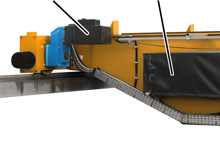
- Attach a rain hood over the crane travel motor.
- Attach a rain hood over the entire wire rope hoist.
- Attach rain hoods over all panels.
Attaching a wind anchor
Strong wind can cause the crane to move in an uncontrolled manner (even when switched off).
Example of a wind anchor at the end of the crane track

- For cranes which are operated completely outdoors: The crane must be able to be secured in a resting position (at the end of the crane track) when work is completed. A wind anchor is located at this resting position for securing the crane.
- For cranes which are operated partly outdoors: If the crane can be moved inside the building when work is finished, a wind anchor is not necessary.
Attaching the wind measuring system
This section only applies to cranes which can only be safely operated up to a defined wind speed.
Wind sensor for wind measuring system
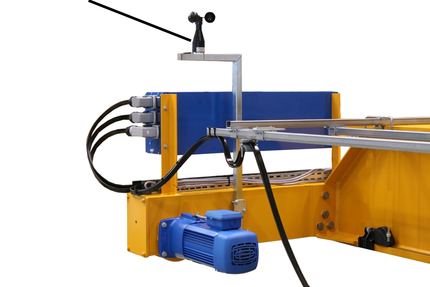
The crane must be equipped with a wind measuring system. The wind measuring system warns if a certain wind speed has been exceeded. The crane must then be run to its resting position (at the end of the crane track) within a specified time.
A wind anchor is located at this resting position for securing the crane. Alternatively, the wind anchor can be of a design that secures the crane at any desired position.
The corresponding wind speed up to which the crane can be operated and the time in which the crane must be able to move to its resting position are both specified in the test log book.
Only with crane with radio remote control: In order to run the crane to its resting position within the specified time, the transmitter must be located where it is easily accessible.
Connecting the crane to the mains supply
Only with overhead travelling cranes
Overview: Electrical connection of the crane
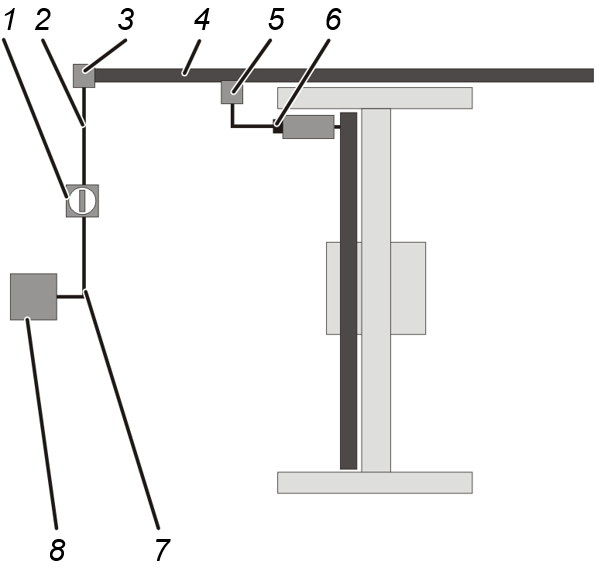
- The power supply for the crane begins at the sub-distribution (8) of the mains supply.
- From there, a line (7) runs to the mains switch (1) of the crane installation.
A mains switch is the best option for isolating the entire crane installation.
The mains switch must be secured against inadvertent switching back on.
The mains switch is usually located under the mains power supply of the crane, e.g. on the building wall or on a building support or concrete support.
- From the mains switch, the riser (2) extends to the feed unit (3).
- The feed unit connects the riser with the mains power supply (4) (usually a conductor system) of the crane.
- The mains power supply contains a mobile current collector (5) which travels with the crane along the crane track.
- The crane is connected to the mains power supply with the mains disconnector plug (6).
This mains disconnector plug is used to isolate the individual crane. The mains disconnector plug can be secured against inadvertent switching back on.
Instead of the mains disconnector plug, a separate circuit isolator (in the form a mains switch) can also be mounted on the crane panel.
The function of the mains disconnector plug or circuit isolator can also be fulfilled by a fuse isolating link. The fuse isolating link is located in the crane control and can be secured against inadvertent switching back on.
Only with pillar slewing jib cranes
Overview: Electrical connection of the crane
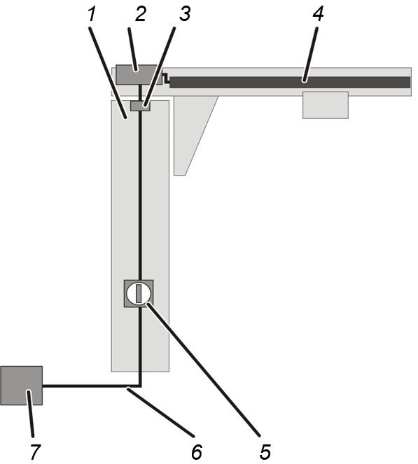
- The power supply for the crane begins at the sub-distribution (7) of the mains supply.
- From there, a line (6) runs to the pillar base of the jib crane and is led through the foundation into the pillar (1).
- The line runs to the mains switch (5) of the crane.
A mains switch is the best option for isolating the entire crane.
The mains switch must be secured against inadvertent switching back on.
The mains switch is located in the pillar at operating height.
- From the mains switch, a line runs inside the pillar and is led out at the top.
For types LS and LSX: The line is led directly out of the pillar.
For type VS: The line runs in the pillar up to the slip ring (3). - For types LS and LSX: The line out of the pillar is connected directly to the trolley power supply (4). Depending on the control, the design may include a housing with fuses for protection of the crane.
For type VS: From the slip ring, the line runs either to the jib arm panel (2) and from there to the trolley power supply (4) or directly from the slip ring to the trolley power supply. Depending on the control, the design may include a housing with fuses for protection of the crane.
Only with wall jib cranes
Overview: Electrical connection of the crane
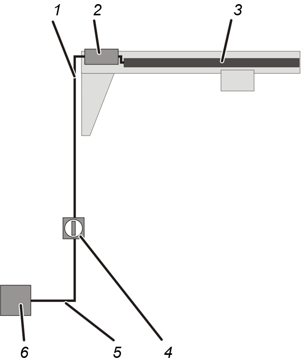
- The power supply for the crane begins at the sub-distribution (6) of the mains supply.
- From there, a line (5) runs to the mains switch (4) of the crane.
A mains switch is the best option for isolating the entire crane.
The mains switch must be secured against inadvertent switching back on.
The mains switch is usually located under the crane, e.g. on the building wall or on a building support or concrete support.
- From the mains switch, the riser (1) extends to the crane.
- For types LW and LWX: The line is connected directly to the trolley power supply (4). Depending on the control, the design may include a housing with fuses for protection of the crane.
For type VW: The line runs either to the jib arm panel (2) and from there to the trolley power supply (4) or directly to the trolley power supply. Depending on the control, the design may include a housing with fuses for protection of the crane.
Only with HB crane types monorail system and double-rail system
Overview: Electrical connection of the HB crane
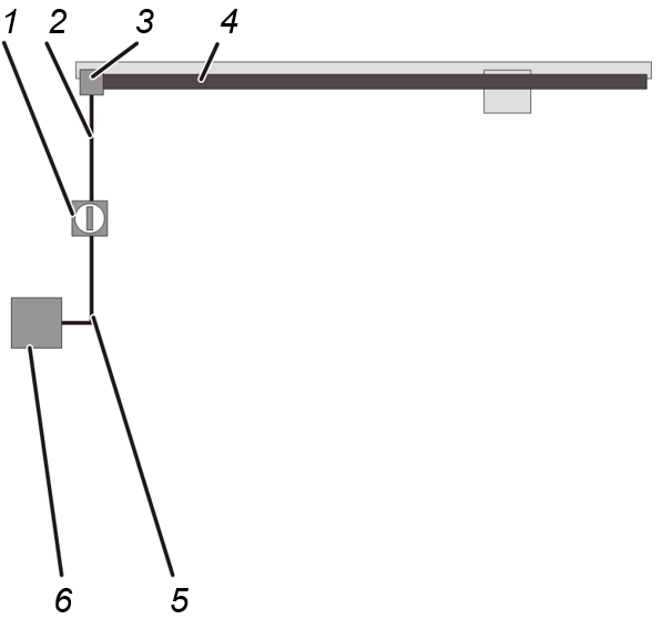
- The power supply for the HB crane begins at the sub-distribution (6) of the mains supply.
- From there, a line (5) runs to the mains switch (1) of the HB crane installation.
A mains switch is the best option for isolating the entire HB crane installation.
The mains switch must be secured against inadvertent switching back on.
The mains switch is usually located under the mains power supply of the HB crane, e.g. on the building wall or on a building support or concrete support.
- From the mains switch, the riser (2) extends to the feed unit (3).
- There the line is connected with the trolley power supply (4). Depending on the control, the design may include a housing with fuses for protection of the crane.
Only with HB crane types single-girder crane and double-girder crane
Overview: Electrical connection of the HB crane
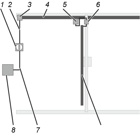
- The power supply for the HB crane begins at the sub-distribution (8) of the mains supply.
- From there, a line (7) runs to the mains switch (1) of the HB crane installation.
A mains switch is the best option for isolating the entire HB crane installation.
The mains switch must be secured against inadvertent switching back on.
The mains switch is usually located under the mains power supply of the HB crane, e.g. on the building wall or on a building support or concrete support.
- From the mains switch, the riser (2) extends to the feed unit (3).
- The feed unit connects the riser with the mains power supply (4) of the crane.
- For conductor systems: The mains power supply contains a mobile current collector (5) which travels with the HB crane along the HB crane runway.
For festoon cable systems: The line of the mains power supply hangs in loops on the HB crane runway and is towed by the HB crane. - The HB crane is connected to the mains power supply.
If the HB crane installation consists of a single HB crane, the mains power supply is connected directly to the HB crane. Depending on the control, the design may include a housing with fuses for protection of the crane.
- If the HB crane installation consists of several HB cranes, there is a circuit isolator on the crane.
This circuit isolator is used to isolate the individual HB cranes. The circuit isolator must be secured against inadvertent switching back on. Depending on the control, the design may include a housing with fuses for protection of the crane.
Only with mobile gantry cranes
Overview: Electrical connection of the crane
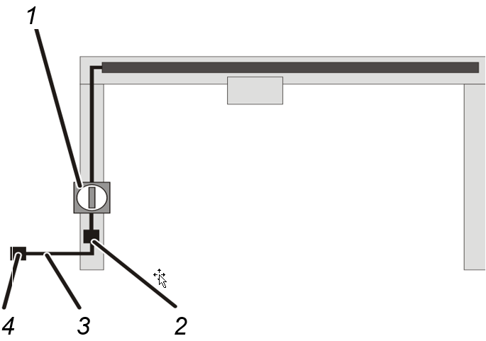
- The power supply for the crane begins at a three-phase socket (4).
- From there, a suitable line with a CEE plug (3) runs to the mains disconnector plug (2) of the crane.
- From there, a line runs to the mains switch (1) of the crane.
The mains switch is located on one of the portal legs on the crane.
Only with single-rail trolley tracks
Overview: Electrical connection of the crane
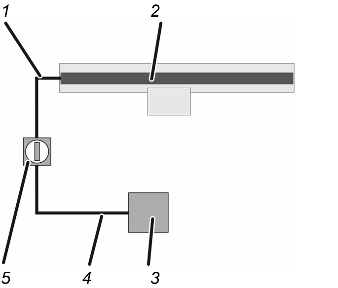
- The power supply for the crane begins at the sub-distribution (3) of the mains supply.
- From there, a line (4) runs to the mains switch (5) of the crane.
A mains switch is the best option for isolating the entire crane.
The mains switch must be secured against inadvertent switching back on.
The mains switch is usually located under the crane, e.g. on the building wall or on a building support or concrete support.
- From the mains switch, the riser (1) extends to the crane.
- There the line is connected to the trolley power supply (2).
Only with solo chain hoists
Overview: Electrical connection of the crane
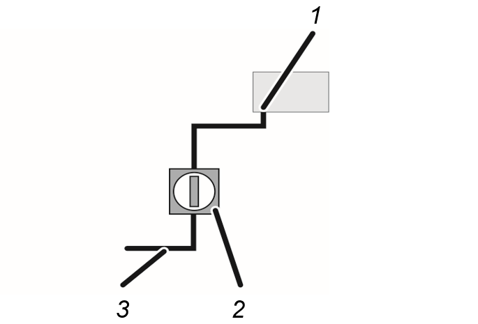
- The power supply for the solo chain hoist is connected according to the on-site conditions in the building.
- The line (3) must have a mains switch as general mains switch for the entire crane installation (2) or a plug-in connection as a mains disconnector plug.
The bayonet coupling (1) on the chain hoist cannot be secured against switching back on and is therefore not suitable as a mains disconnector plug.
Only with solo wire rope hoists
Overview: Electrical connection of the crane
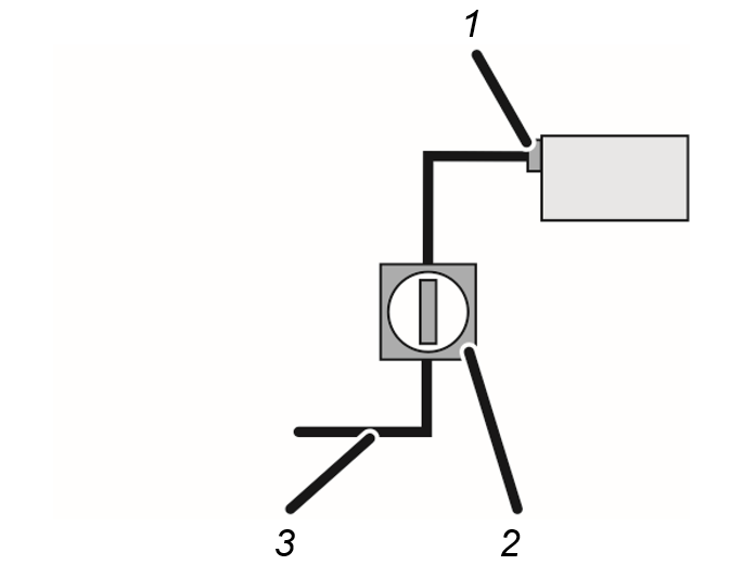
- The power supply for the solo wire rope hoist is connected according to the on-site conditions in the building.
- The mains disconnector plug (1) on the wire rope hoist can be secured against inadvertent switching back on.
- However, it is still recommended that the line (3) have a mains switch as general mains switch (2) for the entire crane installation.
Checking the on-site mains supply
- For cranes without voltage adapting transformer: Compare the operating voltage and mains frequency of the crane with the mains voltage and frequency of the local mains supply.
The operating voltage and mains frequency are specified on the type plates on the crane and in the test log book.
Operating voltage and mains voltage as well as mains frequency must be matched for one another.
- For cranes with voltage adapting transformer: The mains voltage of the local mains supply must be converted to the operating voltage of the crane by a voltage adapting transformer.
Compare the operating voltage and mains frequency at the input of the voltage adapting transformer with the mains voltage and frequency of the local mains supply.
Connecting the crane
- Lay the lines, attach the mains switch and connect the crane.
Checking the rotary field
The crane may only be operated on a 3-phase mains supply with a clockwise rotary field.
- Unlock the emergency stop switch.
- Press the ‘Lift’ button halfway.
- The load hook must run slowly upward or remain stopped (if the top emergency limit switch has already been triggered).
If the load hook travels downwards instead:
- The phases in the mains supply have been interchanged.
- Correct the interchanged phases.
If possible, correct the phases at the point where they were interchanged. Only in exceptional cases should the phases be interchanged again directly on the power line.
Checking protective conductors
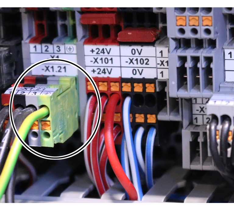
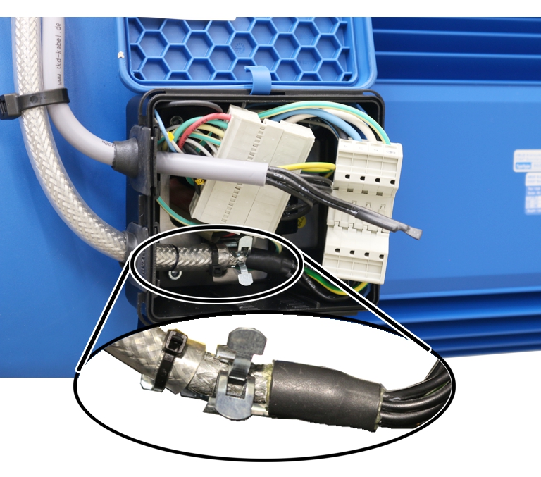
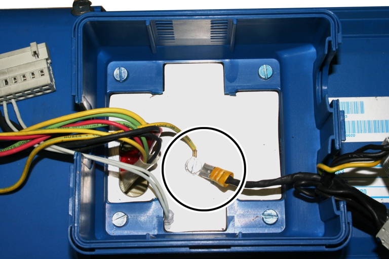
All components of the crane are connected with the protective conductor of the local mains supply. These connections are made through plug-in connections, cable lugs and similar means.
For all protective conductor connections which have been established during the assembly of the crane:
- Carry out a visual inspection.
The protective conductors must be uninterrupted and correctly connected.
Examples of protective conductor connections:
Ensuring electromagnetic compatibility (EMC)
Electrical devices and lines normally generate electromagnetic fields. These fields can negatively affect other devices and cause malfunctions. To best avoid such disturbances, certain basic principles must be observed when working with electrical equipment.
For any electrical work performed on the crane:
In order for the crane to operate without faults, all electrical components and all connection cables must be installed by professionals.
Observe the following points amongst others:
- Do not lay signal lines together with current-conducting lines.
- With frequency converters: guide connection cables for braking resistance and connection cables for motors through the cable fittings in the panel and lay them in a direct path to the frequency converter.
- Lay the shields of shielded cables over a wide area and earth them.
- Do not twist, braid or solder shields. Instead, use the supplied installation material.
- Earth the unused wires of cables in the panel.
Test before initial commissioning
Before the crane can be put into operation for the first time, a test must be carried out. The end user is responsible for this test prior to initial commissioning.
Requirements for the examiner
The end user of the crane is responsible for the proper qualifications of the examiner.
Examples of qualified persons:
- Persons with comprehensive knowledge from specialist training in engineering and in the electrical systems of cranes.
- Persons with sufficient experience in the operation, installation and maintenance of cranes.
- Persons with comprehensive knowledge regarding the relevant technical rules, directives and safety regulations applicable in the respective country.
- Persons receiving regular training from ABUS.
Overview: Inspecting the crane
The qualified person inspecting the crane is responsible for the type and scope of the test.
The items to be checked in the following list represent a general overview regarding the scope of testing of ABUS cranes. Depending on the type, not all components will be present on the crane.
The decision as to whether the crane is in perfect condition may be made only by the person inspecting the crane. Any inadequacies, if found, must be eliminated. The examiner decides whether the crane has to be tested again afterward.
If locally applicable regulations specify further tests, these are likewise to be carried out.
The examiner tests the operational crane. In doing so, it must be ensured that no one is subjected to avoidable dangers.
At least the following points must be checked:
- Check the general condition. The components of the crane installation may not be damaged or rusted, or exhibit any other dangerous material changes.
- Check the condition of the supporting structure. It should not exhibit any damage.
- Check that the crane has been correctly installed and connected. It must be installed and connected in accordance with this and other product manuals.
- Check the hoist drive, trolley drive and crane travel drive. They must be functioning flawlessly. For the test for switching on, see the product manual “Operating the ABUS crane”.
- Test the brakes on the hoist drives, trolley drives and crane travel drives. They must be functioning flawlessly. For the test for switching on, see the product manual “Operating the ABUS crane”.
- Check the hoist limit switches (switching points for safety limit switches and emergency limit switches). The hoist must switch off at the appropriate switching points.
- If available: Check the operating limit switches. The hoist must switch off at the appropriate switching points.
- Check the travel limit switch. The crane travel drives and the trolley drives must switch off at the appropriate switching points.
- Check screws. All screws must be tightened and secured. If they are not, tighten the screws with the appropriate tightening torque and secure them.
- If available: Check warning devices. They must function as intended.
- Check the overload protection (e.g. load indicator system LIS or friction clutch). It must function as intended.
- Check all other safety devices on the crane. They must function as intended.
- If available: Check the condition of the wind anchor. It must function as intended.
- Check the signage. The required signs on the crane must be present and legible. Otherwise, replace the signs.
- Perform a static test of the maximum load capacity.
Test using a test load with 1.25 times the maximum load capacity of the crane.
- Perform a dynamic test of the maximum load capacity.
Test using a test load with 1.1 times the maximum load capacity of the crane.
- Only if necessary: Perform additional country-specific tests.
- Only within the EU: Check whether there is a Declaration of Conformity or a Declaration of Incorporation.
Checking the test log book
Also in countries which do not require a test log book, it is recommended to document the test in the test log book.
- Check the test log book:
- It must be available
- It must be within easy reach of all persons working on or with the crane.
- It must be clearly identified as belonging to the crane.
- All tests carried out (e.g. test before initial commissioning, regular inspections, tests of the crane track, etc.) must be documented.
Documenting the test before initial commissioning
Also in countries which do not require a test log book, it is recommended to document the test in the test log book.
Test log book of crane

- Document the result of the entire test in the test log book.
- Type and scope of the test
- Items of the test still to be evaluated
- Inadequacies detected
- Assessment of whether the crane may be operated
- Decision on whether a re-check is necessary
The test log book and the complete documentation for the crane must be within easy reach of all persons working on or with the crane.
- Mark the regular inspection as having been performed with a label clearly visible from the outside, e.g. through an inspection sticker.
Shutting down the crane
Should the crane need to be put out of service for a longer period:
- Switch off the crane. See the product manual “Operating the ABUS crane”.
- Secure the mains switch so that it cannot be unintentionally switched back on.
Disassembly
If the crane is to be disassembled:
ABUS recommends having personnel who performed the initial commissioning carry out the disassembly. See “Installing and connecting”.
- Disassemble the crane by reversing the sequence of steps described in the section “Putting into operation” in all product manuals.
- Dispose of high-tensile bolts, high-tensile nuts and self-locking nuts. They are only to be used once.
Reassembling the crane
If a disassembled crane is to be reassembled:
ABUS recommends having personnel who performed the initial commissioning carry out the reassembly. See “Installing and connecting”.
- Reassemble the crane as described in the section “Putting into operation” in all product manuals.
- Be sure to use new high-tensile bolts, new high-tensile nuts and new self-locking nuts.
- After reassembly, a new test is required before the initial putting into service. See “Test before initial commissioning”.
Inspection
This section applies to anyone who inspects and accepts the crane in accordance with occupational health and safety requirements
The crane must be regularly inspected in order to guarantee safe operation. The end user is responsible for this regular inspection.
At the start
Test intervals
The regular inspection is performed at least once annually.
Under certain conditions, more frequent regular inspections may be necessary. Reasons include:
- Frequent operation at the load capacity
- Working in multiple shifts
- Frequent use
- Dusty or chemically aggressive environment
The end user is responsible for checking the requirements and determining the test intervals. ABUS will gladly assist you if questions arise.
Requirements for the examiner
The end user of the crane is responsible for the proper qualifications of the examiner.
Examples of qualified persons:
- Persons with comprehensive knowledge from specialist training in engineering and in the electrical systems of cranes.
- Persons with sufficient experience in the operation, installation and maintenance of cranes.
- Persons with comprehensive knowledge regarding the relevant technical rules, directives and safety regulations applicable in the respective country.
- Persons receiving regular training from ABUS.
Maintenance resulting from the regular inspection
The regular inspection occurs in many countries because of national requirements and distinctions that must be observed accordingly.
In addition, the regular inspection is also the basis for maintenance work on the crane which is prescribed by ABUS as manufacturer.
If defects, wear or similar issues are noticed, this is the time to perform the corresponding maintenance work.
Based on this requirement, it can also be useful to adapt the test intervals (see “At the start”) or to inspect components subject to especially high load (see “Testing of components subject to especially high stress”).
As a manufacturer's requirement, the regular inspection must therefore also be performed by the end user if national requirements do not demand any regular inspection or these inspections are not as comprehensive.
Scope of the inspection
The qualified person inspecting the crane is responsible for the type and scope of the test.
Overview: Inspecting the crane
The items to be checked in the following list represent a general overview regarding the scope of testing of ABUS cranes. Depending on the type, not all components will be present on the crane.
The decision as to whether the crane is in perfect condition may be made only by the person inspecting the crane. Any inadequacies, if found, must be eliminated. The examiner decides whether the crane has to be tested again afterward.
If locally applicable regulations specify further tests, these are likewise to be carried out.
General overview of the points to be inspected:
- Check the general condition. The components of the crane installation may not be damaged or rusted, or exhibit any other dangerous material changes.
- Check the condition of the supporting structure. It should not exhibit any damage.
- Check that the crane has been correctly installed and connected. It must be installed and connected in accordance with this and other product manuals.
- Check the hoist drive, trolley drive and crane travel drive. They must be functioning flawlessly. For the test for switching on, see the product manual “Operating the ABUS crane”.
- Test the brakes on the hoist drives, trolley drives and crane travel drives. They must be functioning flawlessly. For the test for switching on, see the product manual “Operating the ABUS crane”.
- Check the hoist limit switches (switching points for safety limit switches and emergency limit switches). The hoist must switch off at the appropriate switching points.
- If available: Check the operating limit switches. The hoist must switch off at the appropriate switching points.
- Check the travel limit switch. The crane travel drives and the trolley drives must switch off at the appropriate switching points.
- Check screws. All screws must be tightened and secured. If they are not, tighten the screws with the appropriate tightening torque and secure them.
- If available: Check warning devices. They must function as intended.
- Check the overload protection (e.g. load indicator system LIS or friction clutch). It must function as intended.
- Check all other safety devices on the crane. They must function as intended.
- If available: Check the condition of the wind anchor. It must function as intended.
- Check the signage. The required signs on the crane must be present and legible. Otherwise, replace the signs.
- Check weld seams. They should not be cracked or broken.
- Check the condition of the paintwork. It should not be scratched or peeling. Otherwise, remove peeling paint and touch up the paint coat.
- Check the load hook. See “Checking the load hook”.
- Check the hoist drive, trolley drive and crane travel drive for tightness. The drives should not exhibit any exterior cracks or traces of leaked lubricant.
- Check the air gap and brake lining thickness of the brakes on the hoist drives, trolley drives and crane travel drives. The air gap width must match that specified in the corresponding product manual. The brake lining thickness must match that specified in the respective product manual. Otherwise, adjust the air gap and, if possible, change the brake rotor with brake lining or the fan blade with brake lining.
If the width of the air gap is still within the permitted range but the wear behaviour indicates the air gap will be wider than permitted before the next inspection: The brake must now be adjusted accordingly or the exchange of the brake rotor with brake lining or fan blade with brake lining must be done now.
- If necessary: Check the load capacity.
Check the load capacity using a test load approaching the maximum load capacity of the crane.
- Check the lubrication of all moving parts. See “Lubricants”.
- If applicable: Inspect conductor system. See “Inspecting the conductor system”.
Only with wire rope hoists
- Inspect the wire rope. See “Inspecting the wire rope”.
- Check the wire rope (on the cable drum and on the fixed point crosshead) and check the cable guide. The components should not be damaged, heavily worn, broken or loose.
- Check the wheel flange wear of the wheels on the wire rope hoist.
- Check the braking distance of the trolley drive.
- Check the diameter of the guide rollers on the wire rope hoist.
- Check the wheel diameters on the wire rope hoist.
- Check the condition of the safety buffer on the wire rope hoist.
- Check the condition of the bottom block (visual inspection).
- Check the edge protection on the bottom block (visual inspection).
- Check the rope wedge protrusion.
Only with chain hoists
- Inspect the chain. See “Inspecting the chain”.
- Check additional components. See the product manual for the chain hoist.
Only with cranes for operation in unprotected environments
- Check rain hoods and similar covers for secure fit.
- Check panels and connector housings. No water should have penetrated and the housings must be sealed.
- Check the electrical system. Contacts and cables should not exhibit any areas of corrosion.
- Check the lubricant in the bearings. The bearings should not be eroded or exhibit corrosion.
- Check the test log book. See “Checking the test log book”.
- Determine the already elapsed portion of the theoretical service life. See “Checking the remaining service life”.
- Only if necessary: Perform additional country-specific tests.
- Document the test. See “Documenting the test”.
Also in countries which do not require a test log book, it is recommended to document the test in the test log book.
Checking the load hook
Only with chain hoists
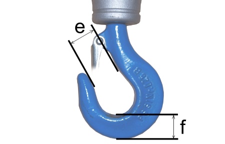
- Measure the widening ‘e’ of the load hook.
- Measure the base height 'f' of the load hook.
- The measured values should neither exceed nor fall short of the values in the table.
Size of load hook |
Type of load hook |
Max. widening ‘e’ [mm] |
Min. base height 'f' [mm] |
Material |
|---|---|---|---|---|
012 |
single |
26.4 |
18.1 |
STE 355 |
025 |
single |
30.8 |
22.8 |
STE 355 |
05 |
single |
37.5 |
29.5 |
34 CrMo 4 |
1 |
single |
44.0 |
38.0 |
34 CrMo 4 |
1.6 |
single |
49.5 |
45.6 |
34 CrMo 4 |
- If the load hook has been widened to a greater degree than is allowed or if the base height is below the permissible limit, replace the load hook.
- If the load hook is deformed (even if within the measurements given above): Inspect the surface for cracks.
Only with wire rope hoists
Checking for ease of movement
Load hook crosshead
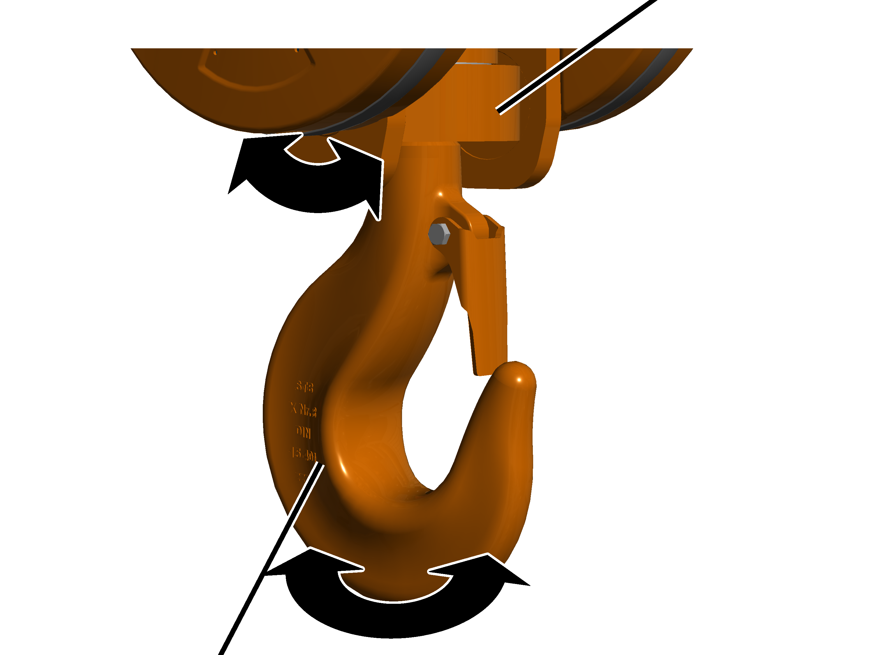
- Rotate the load hook backwards and forwards.
The load hook must be easy to move and freely rotatable.
- Slew the load hook backwards and forwards at the load hook crosshead.
The load hook crosshead must be freely slewable.
- If the load hook is not easy to move or freely rotatable or slewable, it must be repaired.
ABUS Service will gladly provide assistance if needed. See “ABUS Service”.
Inspecting the bracket on the bottom block
Bracket
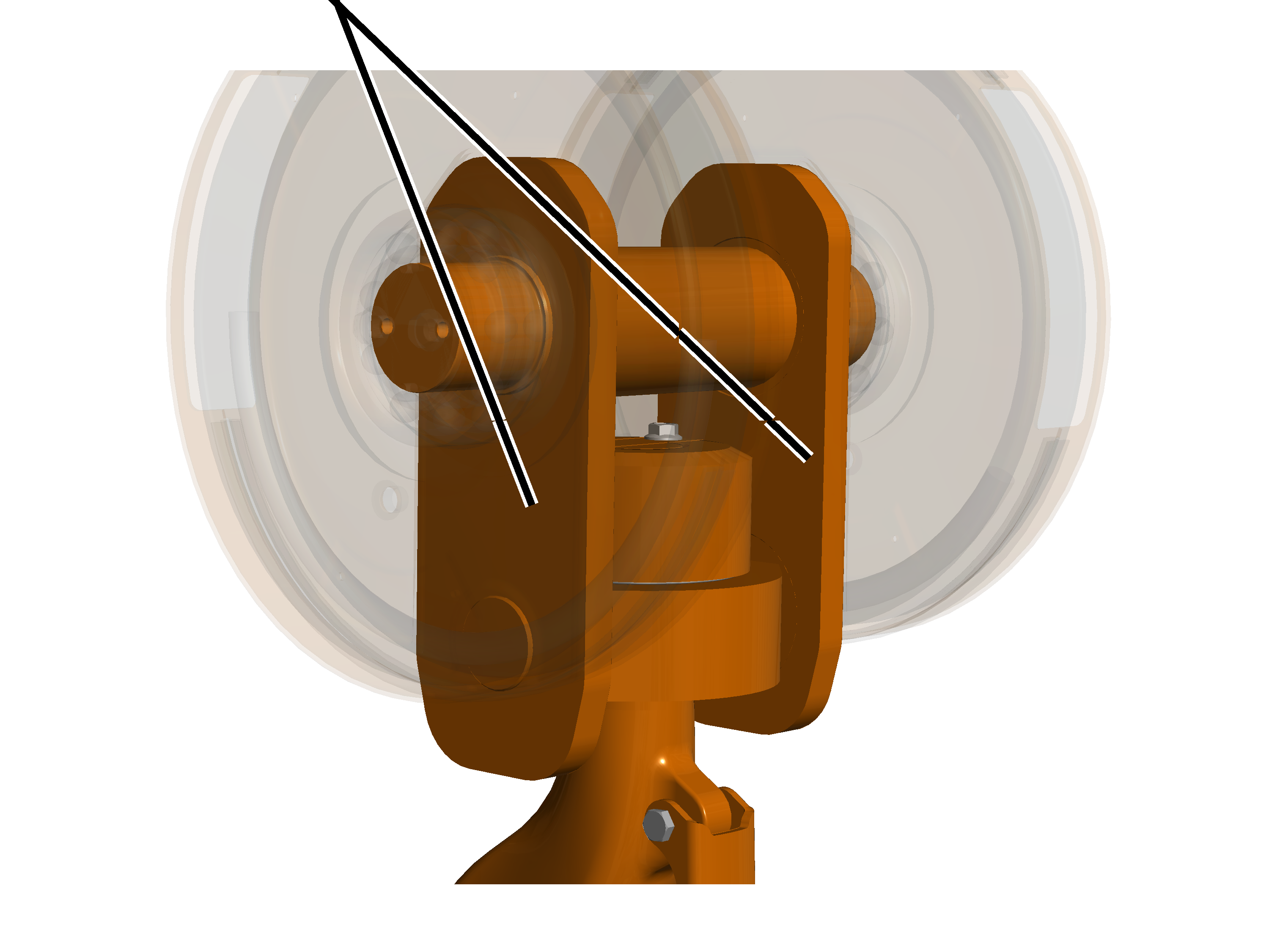
- Inspect the brackets. They must not exhibit any cracking, deformation or other signs of damage.
- If the brackets are deformed or damaged in any other way, they must be replaced.
Measuring deformation and wear of the load hook
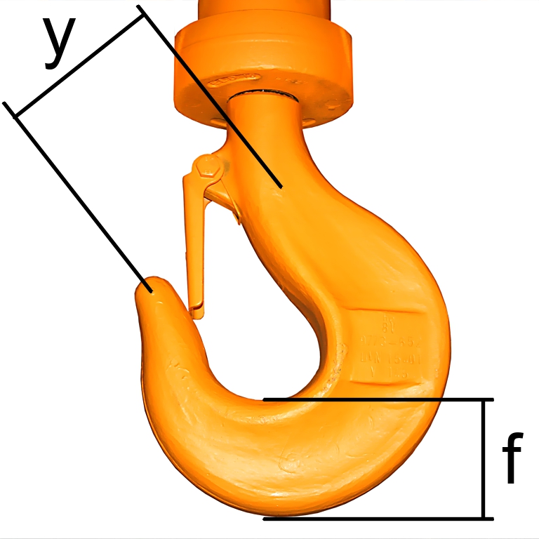
- Measure the distance ‘y’ between the two stamped markings.
- Read the reference distance for ‘y’ from the test log book or, if applicable, from the load hook itself.
The measured distance 'y' must not be greater than 1.1 times the reference distance 'y'.
With ramshorn hooks, the distances 'y1' and 'y2' from the engraved marking on the tip of the load hook to the marking on the shaft must each be measured and compared separately.
- Measure the base height 'f' of the load hook.
- Compare the measured value with the table.
The measured base height ‘f’ must not be smaller than given in the table. The table specifies the minimum base height.
Size of load hook |
Type of load hook |
Min. base height 'f' [mm] |
|---|---|---|
1 |
Normal hook |
38 |
1.6 |
Normal hook |
45.6 |
2.5 |
Ramshorn hook |
47.5 |
2.5 |
Normal hook |
55.1 |
4 |
Ramshorn hook |
57 |
4 |
Normal hook |
63.7 |
6 |
Ramshorn hook |
71.3 |
6 |
Normal hook |
80.8 |
8 |
Ramshorn hook |
80.8 |
8 |
Normal hook |
90.3 |
10 |
Ramshorn hook |
90.3 |
10 |
Normal hook |
100.7 |
12 |
Ramshorn hook |
100.7 |
12 |
Normal hook |
112.1 |
16 |
Ramshorn hook |
112.1 |
16 |
Normal hook |
125.4 |
20 |
Ramshorn hook |
125.4 |
20 |
Normal hook |
142.5 |
25 |
Ramshorn hook |
142.5 |
25 |
Normal hook |
161.5 |
32 |
Ramshorn hook |
161.5 |
32 |
Normal hook |
180.5 |
40 |
Ramshorn hook |
180.5 |
40 |
Normal hook |
201.4 |
- If the load hook has been widened to a greater degree than is allowed or if the base height is below the permissible limit, replace the load hook.
Do not carry out any repair welding (e.g. build-up welding) on the load hook or on the load hook nut.
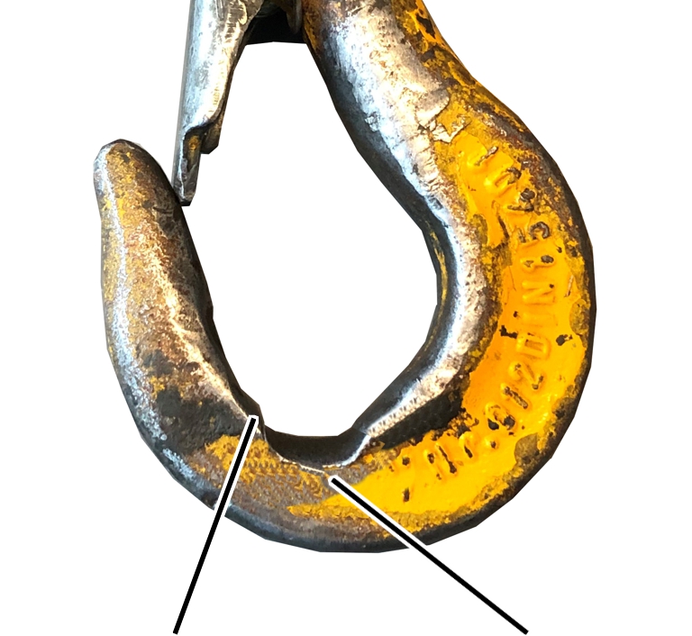
- Check the wear surfaces in the hook bed. They must merge gradually with the surrounding surfaces. They must not have any sharp score marks and edges or other surface faults.
- Inspect the edges. The side edges on the hook should not have any exterior protruding burrs or similar surface faults.
- If the wear surfaces or side edges do have sharp score marks or edges, these may be smoothed (e.g. filed). The limit values for base height given above must be observed even after smoothing.
Inspecting the load hook surface
- Inspect the load hook surface. It must not have any faults, cracks or corrosion.
- If the surface of the load hook is to any extent not OK, disassemble the load hook and inspect the surface of the hook shank. It must not have any faults, cracks or corrosion.
Inspecting the anti-rotation device of the load hook nut
With load hooks with anti-rotation device through tensioner sleeve:
Load hook nut
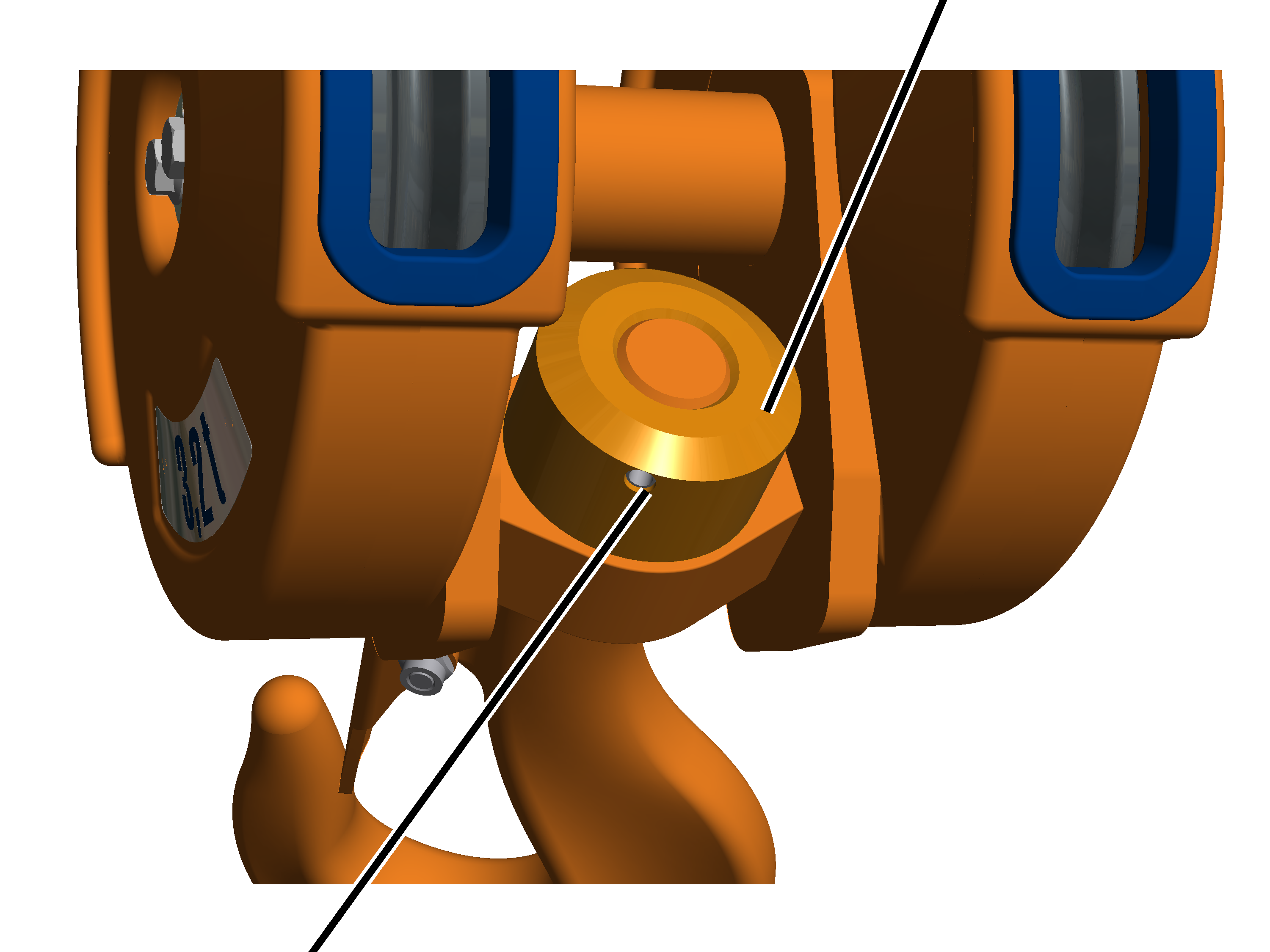
- Tilt the load hook until the anti-rotation device is clearly visible.
- Inspect the anti-rotation device. The locking pin must be present, may not be damaged or broken and it must sit securely.
- If the locking pin is missing or damaged, it must be replaced.
With load hooks with anti-rotation device through locking plate:
Safety plate
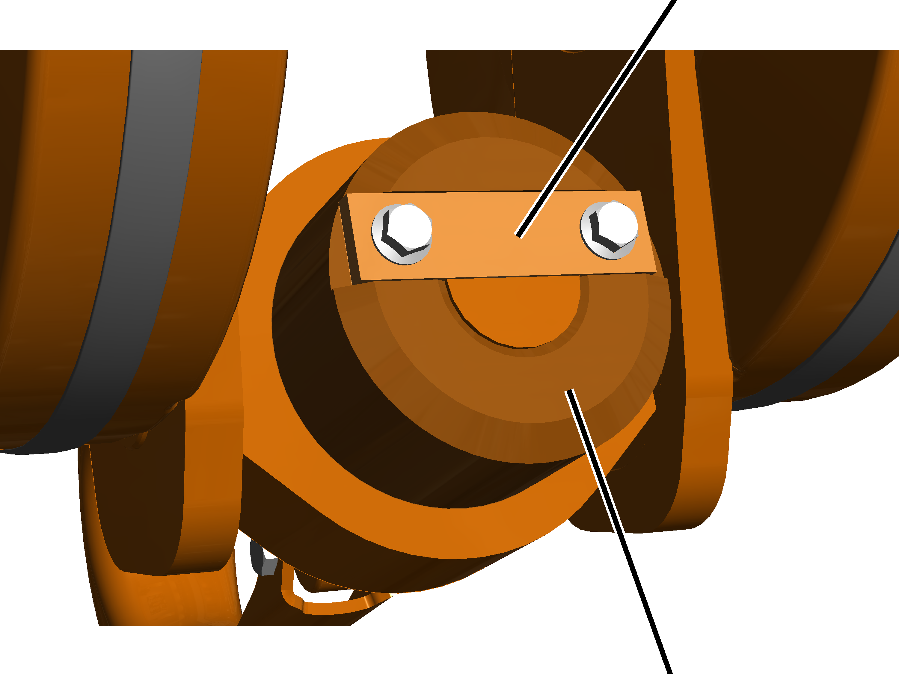
- Tilt the load hook until the anti-rotation device is clearly visible.
- Inspect the anti-rotation device. The safety plate must be present, undamaged and fit securely.
- If the locking plate is missing or damaged, it must be replaced.
Inspecting the hook safety latch
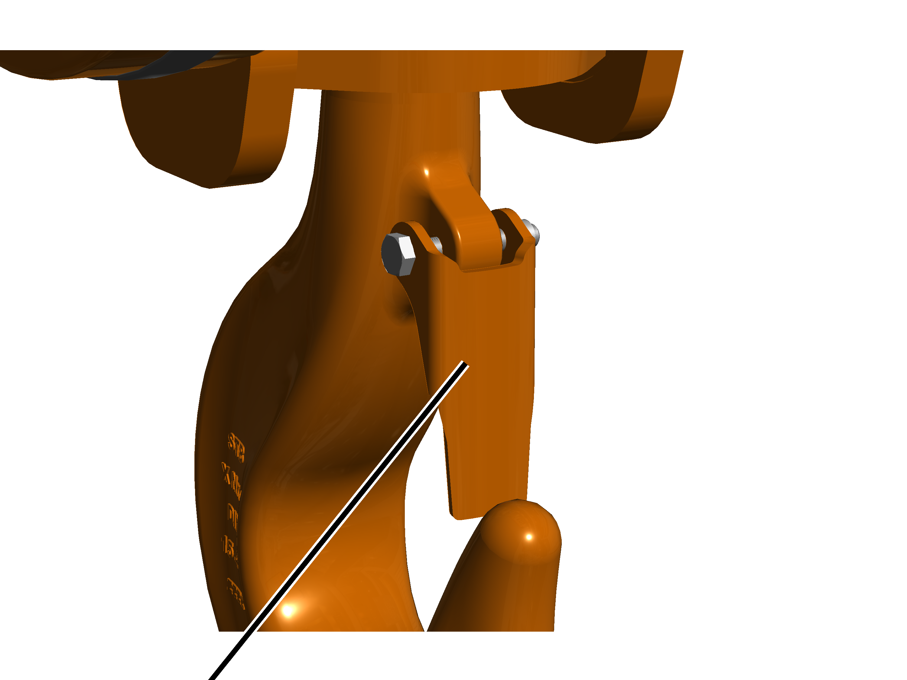
- Inspect the hook safety latch. It must be present, functional and easy to move, and must not be deformed or damaged in any other way.
- If the hook safety latch is missing, damaged or not working properly, it must be replaced.
Inspecting the conductor system
Only with conductor system as mains power supply or trolley power supply
This section is only applicable if a conductor system is used as the mains power supply or the trolley power supply.
Inspecting the conductor system
- Inspect the sections of the conductor system, the joints of the sections and the suspensions. The parts should not be broken, deformed or otherwise damaged.
- Inspect the inside of the conductor system. It should not be heavily soiled (e.g. due to rubbing of the carbon strip or dirt in the surroundings).
- Inspect the sections of the conductor system. The surface of current-conducting rails must be smooth.
- If the conductor system is heavily soiled or the surface of the rails is not smooth, blow off with compressed air or clean with a cleaning trolley.
The cleaning trolley is supplied through ABUS Service. See “ABUS Service”.
Inspecting current collectors
- Check the running characteristics of the current collector. It must run smoothly and without resistance in the conductor system.
- Take the current collector out of the conductor system.
- Check the thickness of the carbon strips. The carbon strips should not show more wear than is permissible.
How much wear the carbon strips are allowed to have is either specified on the current collector (according to the conductor system) or the maximum wear is indicated by a marking on the carbon strip itself.
- Check the wheels of the current collector. They must run smoothly and be free of damage.
- If the current collector does not run smoothly or the carbon strips are more heavily worn than is allowed, replace the current collector completely, or (if possible) replace the carbon strips.
Inspecting the wire rope
Only with wire rope hoists
- Inspect the entire wire rope for damage. The damage shown here or any similar damage should not be detectable on the wire rope.
Examples of damage:
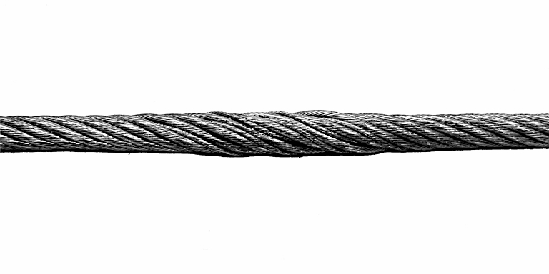
The joining of the wire rope has opened. The inner strands of the wire rope are visible.
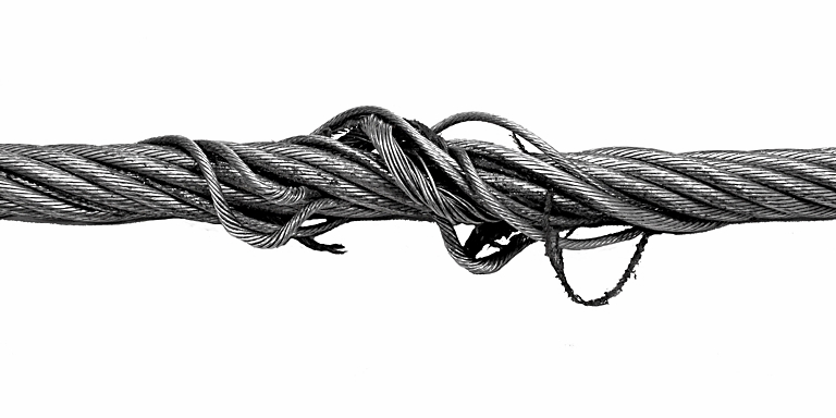
Loops have formed in the wire rope.
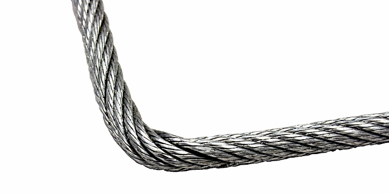
There is a kink in the wire rope. This results from violent external forces being applied to the wire rope.
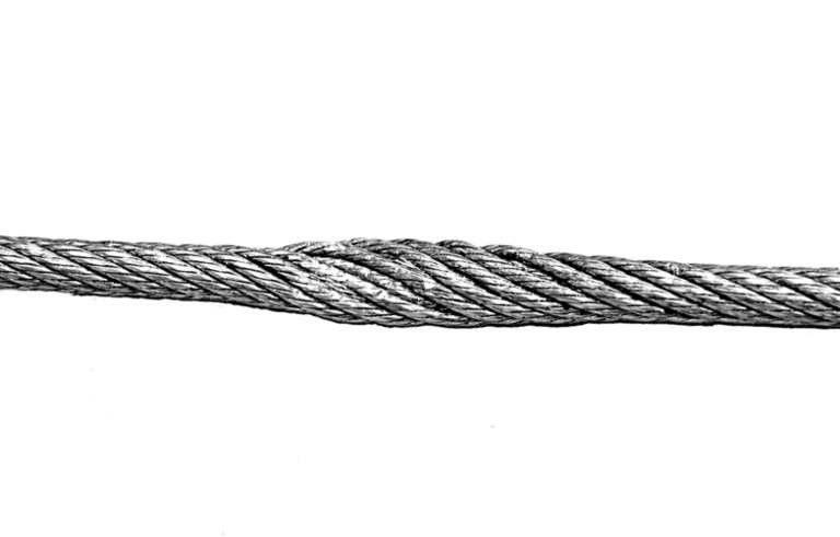
The wire rope is flattened at one point. This results from the wire rope being pinched.
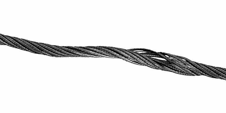
A bird cage has formed in the wire rope. This results from violent untwisting of the wire rope.
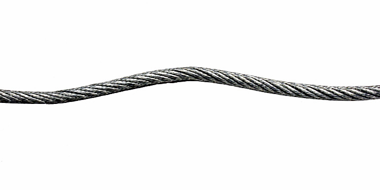
The wire rope has a corkscrew-type deformation.
- Check the entire wire rope for broken wires. The wire rope must not exhibit more broken wires in a length of 6 times its diameter or 30 times its diameter than is specified for these lengths on the ABUS manufacturer's certificate for wire ropes in the test log book.
Examples of broken wires:
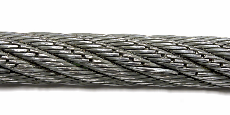
Multiple broken wires. Broken wires are signs of normal wear of the wire rope. They occur when the wire rope is bent on the reels under load.
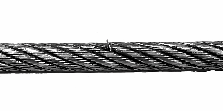
Broken wire with protruding wire end.
- If damage such as that pictured or similar damage is detected on the wire rope, replace the wire rope with a new one.
- If the wire rope has broken wires, but not exceeding the permissible number, shorten the test interval until the next test.
- If the wire rope has more broken wires than permitted, replace the wire rope with a new one.
Inspecting the chain
Only with chain hoists
- Inspect the condition of the chain (lubrication, corrosion, surface damage) and check the chain's wear (length of the chain over 11 chain links). See the product manual for the chain hoist.
Examples of damage:

The chain link is heavily worn.

The chain link is mechanically damaged.
Basics for determining the remaining service life
To avoid accidents with the crane due to wear and age, it is essential to always ensure that the hoist operates within a safe working period.
Actual hours of use (S) and theoretical service life (D)
The hoist operates within a safe operating period if the actual hours of use (S) are fewer than the number of hours representing the theoretical service life (D).
The theoretical service life (D) is determined and specified by ABUS according to the generally accepted engineering standards. The theoretical service life is given in full-load hours. A full-load hour is defined as the hoist having operated at its maximum load capacity for one hour.
The actual hours of use (S) of the hoist must be determined by the end user. The value must be determined based on the operating hours, the load spectrum and additional factors.
Load spectrum
In order to also take into account the operating phases of the hoist in which the hoist was not operating at maximum load capacity, but instead lifted lesser loads, there are four different load spectrums (Km). The load spectrum (Km) is a mathematical factor. It specifies how great a load is actually placed on the hoist during operation.
There are four load spectrums
- Light (Km = 0.5)
- Medium (Km = 0.5 to 0.63)
- Heavy (Km = 0.63 to 0.8)
- Very heavy (Km = 0.8 to 1.0)
In the light load spectrum, for example, the hoist often runs with an empty load hook and transports light loads (in relation to its maximum load capacity). In the very heavy load spectrum, for example, the hoist seldom runs with an empty load hook and nearly always transports loads at its maximum load capacity.
The load spectrum thus specifies the degree to which the hoist is subjected to its maximum load capacity or only to lesser operating demands.
Examples:
Maximum stress only in exceptional instancesOtherwise very little stress
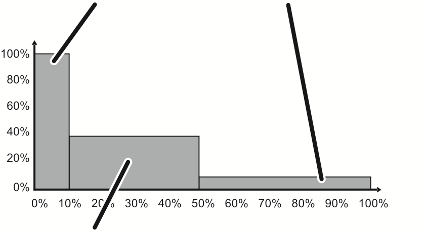
Maximum stress only in exceptional instancesOtherwise little stress
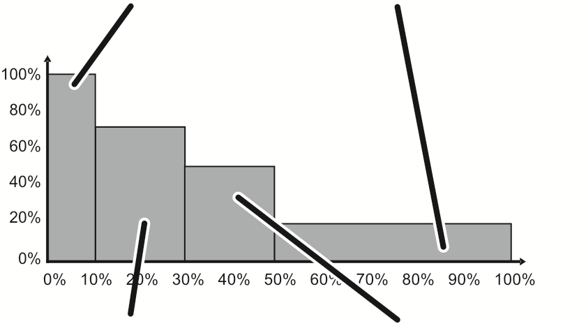
Otherwise medium stress
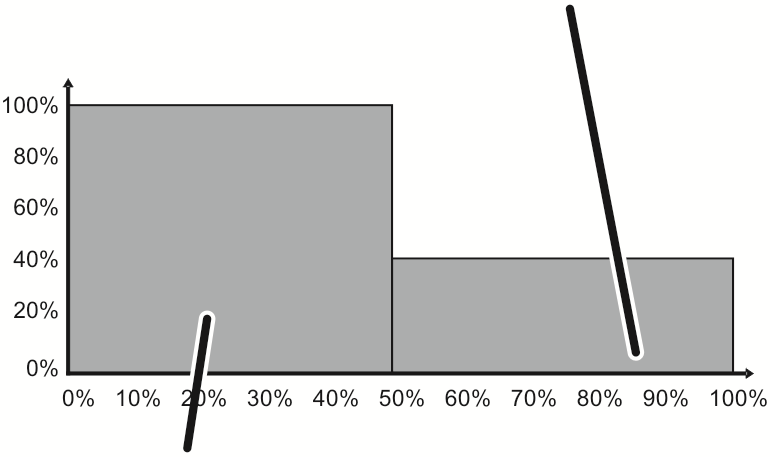
Otherwise high stress
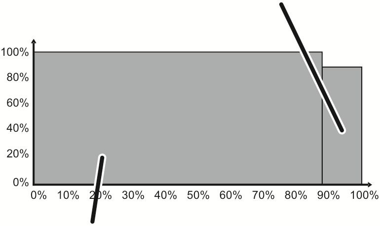
Checking the remaining service life
The actual hours of use (S) must be documented within the scope of a regular inspection at least once yearly.
The remaining service life will continue to be evaluated during the regular inspection. This is done by determining whether the actual hours of use (S) are still fewer than the number of hours representing the theoretical service life (D).
If the remaining service life is very limited or zero, the hoist may no longer be used. In this case, a general overhaul of the entire hoist by ABUS as manufacturer is required.
Determining the remaining service life
- The exact procedure for determining the remaining service life can be found in FEM 9.755.
Overview:
- The classification according to FEM for the hoist drive can be read on the type plate.
- Read the corresponding theoretical service life D in the table.
Classification according to FEM |
1Bm |
1Am |
2m |
3m |
4m |
|---|---|---|---|---|---|
Light |
3200 |
6300 |
12500 |
25000 |
50000 |
Medium |
1600 |
3200 |
6300 |
12500 |
25000 |
Heavy |
800 |
1600 |
3200 |
6300 |
12500 |
Very heavy |
400 |
800 |
1600 |
3200 |
6300 |
- Determine the actual hours of use.
This can be done using a load population recorder, an operating hours counter, through documentation of usage or by estimating.
- Compare the theoretical service life (D) and the determined actual hours of use (S).
- The calculated remaining service life of the hoist is to be be documented in the test log book.
- If the theoretical service life of the hoist has been reached: Take the hoist out of service and have ABUS perform a general overhaul.
Checking the test log book
Also in countries which do not require a test log book, it is recommended to document the test in the test log book.
- Check the test log book:
- It must be available
- It must be within easy reach of all persons working on or with the crane.
- It must be clearly identified as belonging to the crane.
- All tests carried out (e.g. test before initial commissioning, regular inspections, tests of the crane track, etc.) must be documented.
Documenting the test
Also in countries which do not require a test log book, it is recommended to document the test in the test log book.
Test log book of crane

- Document the result of the entire test in the test log book.
- Type and scope of the test
- Items of the test still to be evaluated
- Inadequacies detected
- Assessment of whether the crane may be operated
- Decision on whether a re-check is necessary
The test log book and the complete documentation for the crane must be within easy reach of all persons working on or with the crane.
- Mark the regular inspection as having been performed with a label clearly visible from the outside, e.g. through an inspection sticker.
Acceptance test after substantial changes
Once substantial changes have been made, these require an acceptance test.
This test is identical to the test before initial commissioning. See “Test before initial commissioning”.
The test is only necessary on the parts of the crane that have undergone substantial change.
Examples of substantial changes are:
- Changing the power supply
- Replacement of trolleys
- Converting or modifying the travel drive or hoist drive
- Increasing the maximum load capacity of a crane installation
- Extension of a crane track
- Using cranes on different crane tracks
- Welding on load-bearing structural elements
- Design modifications to a supporting structure
- Conversion of components of the supporting structure. This includes the crane track, the mountings, the building beams, the building supports, the concrete girders and the concrete supports.
- Change of the operating conditions of the crane installation in relation to the classification according to FEM.
- Conversion to a different type of control (e.g. radio remote control).
- Changing the mode of operation in regard to the operating time class and the load spectrum (e.g. switching from single-shift operation to multiple-shift operation).
Testing of components subject to especially high stress
During operation of the crane, situations can arise in which the individual components are subject to higher stress than expected.
This can result in damage that might be detected too late in the regular inspection at the previously specified test intervals.
Nevertheless, safe operation must be ensured for these components as well.
It may thus be necessary to check individual components of a crane or entire modules especially frequently. These additional tests are then regularly required at briefer intervals in addition to the regular inspection.
Examples:
- The risk assessment has revealed that certain components (e.g. brakes or wire ropes) are subject to especially high stress.
Example: In a food-processing facility, a wire rope is not permitted to be lubricated for reasons of hygiene. The risk assessment clearly shows that this wire rope is subject to especially high stress. It must therefore be checked more frequently in addition to the regular inspection.
- The repeated failure of a component has subjected it to especially high stress.
Example: On a crane, the brake lining became worn a second time within a short period due to especially high stress. It must therefore be checked more frequently in addition to the regular inspection.
- The operating conditions were changed and it is not known if these operating conditions place more stress on the crane than before.
Example: The crane is used for a new operation. The load-bearing components of the crane, especially the wire rope, must be checked more frequently in addition to the regular inspection until damage due to the new operating conditions can be ruled out.
- The crane was placed under unusually high stress due to a near-accident.
Example: A load was inadvertently caught with the crane. The load-bearing components of the crane, especially the wire rope, must be checked more frequently in addition to the regular inspection until damage can be ruled out.
The end user is responsible for the inspection of components under especially high stress. The end user also specifies the inspection and test intervals at which the highly stressed components are to be checked. These test intervals can be considerably shorter than the regular inspection.
ABUS Service will gladly provide assistance if needed. See “ABUS Service”.
The end user of the crane is responsible for the proper qualifications of the examiner. For the qualifications, see “Test before initial commissioning”.
General plan
In this general plan you will find listed the tests which must be performed on the crane at various intervals.
This general plan is a summary of the information from different chapters and different product manuals.
Information on the tasks to be carried out can be found under the following:
- Tasks which must be done every day (these are primarily functional tests) are usually performed by the crane operator prior to beginning work.
These tasks are therefore listed in all product manuals in the chapter “Operation” in the section “Check before beginning work and switching on”, as well as in the product manual “Operating the ABUS crane”.
- Tasks which are performed in a regular inspection are carried out in accordance with the national regulations by, for example, ABUS Service, the end user's own maintenance personnel, or specialist service or inspection companies.
These tasks are therefore listed in all product manuals in the section “Inspection”. See “Scope of the inspection”.
- Lubricant changes which must be performed in a general overhaul, a regular inspection, or in some other deviating interval, are carried out by, for example, ABUS Service, the end user's own maintenance personnel, or specialist service companies.
These tasks are therefore listed in this and all other product manuals in the section “Lubricants”.
Overhead travelling crane |
Jib crane |
HB crane |
Wire rope hoist |
Chain hoist |
Push trolley/electric trolley |
Daily |
Regular inspection |
|
|---|---|---|---|---|---|---|---|---|
Functional tests |
||||||||
X |
X |
X |
X |
X |
X |
Are the hoist drive and travel drives functional? |
X |
X |
X |
X |
X |
X |
X |
X |
Are the brakes functional on the hoist drive and travel drives? |
X |
X |
X |
X |
X |
X |
X |
X |
Is the emergency stop button functional? |
X |
X |
X |
X |
Is the overload protection functional? |
X |
|||||
X |
X |
For hoists without an operating limit switch: Is the top emergency limit switch functional? |
X |
X |
||||
X |
X |
For hoists with an operating limit switch: Is the top operating limit switch functional? |
X |
X |
||||
X |
X |
For hoists with an operating limit switch: Is the top emergency limit switch functional? |
X |
|||||
X |
X |
Is the safety limit switch functional? |
X |
|||||
X |
X |
X |
X |
Are the trolley travel and crane travel limit switches functional (braking function / shut-down)? |
X |
X |
||
X |
X |
X |
X |
X |
X |
If available: Are the warning devices functional? |
X |
X |
X |
X |
X |
X |
X |
X |
Are all other safety devices functional? |
X |
X |
X |
X |
X |
If available: Is the wind anchor functional? |
X |
Overhead travelling crane |
Jib crane |
HB crane |
Wire rope hoist |
Chain hoist |
Push trolley/electric trolley |
Daily |
Regular inspection |
|
|---|---|---|---|---|---|---|---|---|
Inspection of components |
||||||||
X |
X |
X |
X |
X |
X |
Can any damage be detected (rust, loose parts, leaking oil, missing screws,...)? |
X |
X |
X |
X |
X |
X |
X |
X |
Can any damage be detected on the supporting structure? |
X |
|
X |
X |
X |
X |
X |
X |
Is the crane properly installed and connected? |
X |
|
X |
X |
X |
X |
X |
X |
Are all screws tightened and secured? |
X |
|
X |
X |
Is the load hook rotatable and otherwise OK? |
X |
X |
||||
X |
X |
Can any damage be detected on the wire rope or the chain? |
X |
X |
||||
X |
Can any broken wires be detected on the wire rope? |
X |
X |
|||||
X |
Can any damage be detected on the mountings of the wire rope (on the cable drum and on the fixed point crosshead) or on the cable guide? |
X |
||||||
X |
Is the rope wedge protrusion correct? |
X |
||||||
X |
X |
X |
X |
X |
X |
Are the required signs present and legible? |
X |
|
X |
X |
X |
X |
X |
Can any damage be detected on the weld seams? |
X |
||
X |
X |
X |
X |
X |
X |
Can any damage be detected on the paintwork? |
X |
|
X |
X |
Is the load hook worn, misshapen or damaged? |
X |
|||||
X |
X |
X |
X |
X |
Are the gear units of the travel drives and hoist drives sealed? |
X |
||
X |
X |
X |
X |
X |
X |
Is the air gap and the brake lining thickness of the brakes on the hoist drives and travel drives correct? |
X |
|
X |
X |
X |
X |
X |
X |
Does the crane reach its maximum load capacity? |
X |
|
X |
X |
X |
X |
X |
X |
Are all moving parts lubricated? |
X |
|
X |
X |
If applicable: Is the conductor system in order, clean and running smoothly on the current-conducting rails? |
X |
|||||
X |
X |
If applicable: Are the carbon strips on the current collector still adequate and does the current collector run smoothly? |
X |
|||||
X |
X |
X |
X |
X |
X |
If applicable: Are the rain hoods mounted correctly? |
X |
|
X |
X |
X |
X |
X |
X |
Are the panels and other electrical housings dry on the inside, sealed against water penetration and the electrical components free from corrosion? |
X |
|
X |
X |
X |
Are the wheel flanges of the wheels worn? |
X |
||||
X |
X |
X |
X |
X |
Is the braking distance of the travel drives OK? |
X |
||
X |
X |
If available: Is the diameter of the guide rollers OK? |
X |
|||||
X |
X |
X |
Is the wheel diameter OK? |
X |
||||
X |
X |
Is the bottom block OK? |
X |
|||||
X |
Is the edge protection on the bottom block OK? |
X |
||||||
X |
X |
X |
X |
X |
Are the safety buffers OK? |
X |
||
X |
X |
X |
X |
X |
X |
Is the test log book OK? |
X |
|
X |
X |
Has the theoretical service life been reached? |
X |
|||||
X |
X |
X |
X |
X |
X |
Do country-specific tests need to be performed? |
X |
Maintenance
This section applies to anyone who maintains, repairs or modifies the crane.
The end user of the crane is responsible for the selection and proper qualifications of the maintenance personnel.
Examples of qualified persons:
- Persons with comprehensive knowledge from specialist training in engineering and in the electrical systems of cranes.
- Persons with sufficient experience in the operation, installation and maintenance of cranes.
- Persons with comprehensive knowledge regarding the relevant technical rules, directives and safety regulations applicable in the respective country.
- Persons receiving regular training from ABUS.
ABUS assumes no liability for damage due to incorrectly performed maintenance work done by unqualified personnel.
ABUS recommends having the maintenance work performed by ABUS Service.
Use only original ABUS replacement parts. Otherwise, all warranty claims will be rendered invalid.
Switching off the crane
Before performing any work on the crane:
- Switch off the crane.
Otherwise, components of the crane electrical system will be carrying voltage.
It could also happen that another person inadvertently uses the crane, resulting in objects being thrown from the crane or persons falling from the lifting platforms.
If the crane must remain switched on for maintenance work (e.g. changing the wire rope):
- Take other measures to ensure that the risk of electric shock is prevented and that other persons do not inadvertently use the crane.
Switching off the crane at the mains switch
Mains switch
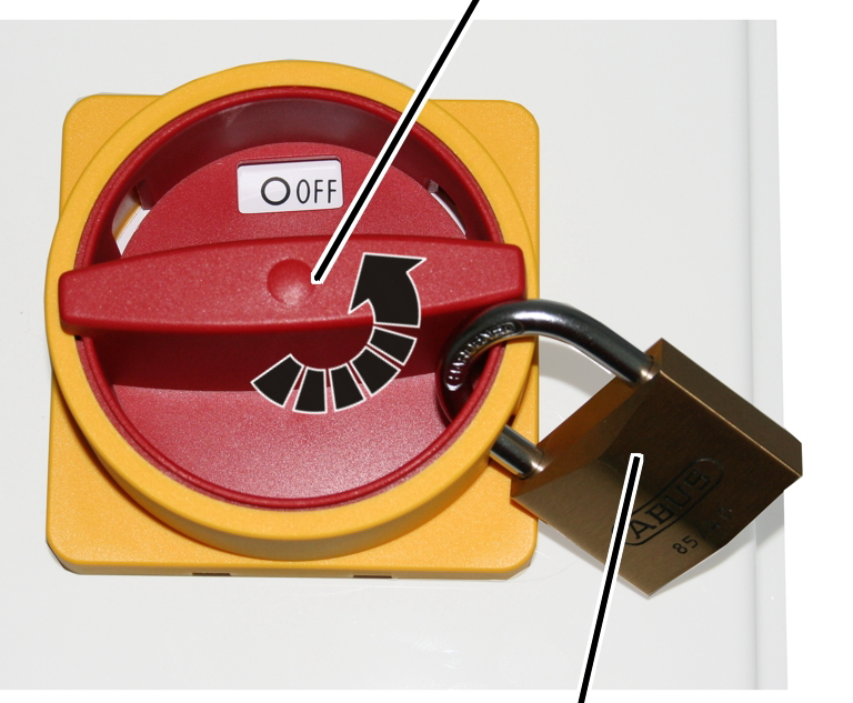
- Turn the mains switch to 0.
- Secure with one or more padlocks.
Only with cranes with crane panels
This section only applies if the crane has a crane panel (e.g. overhead travelling cranes and, depending on the version and options, possibly also jib cranes and HB cranes).
Switching off the crane with a mains disconnector plug
This is primarily useful if the entire crane installation cannot be switched off with a general mains switch.
Mains disconnector plug
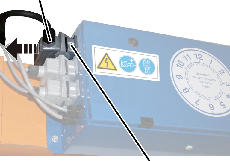
- Pull the mains disconnector plug out of the socket on the crane panel.
- Secure the socket with a padlock to ensure it is not plugged back in accidentally.
Only with chain hoists: The bayonet coupling on the chain hoist cannot be secured against switching back on and is therefore not suitable as a mains disconnector plug.
Instructions regarding safety: Prior to maintenance
Comply with the following safety instructions before beginning with maintenance:
Instructions regarding safety: During maintenance
Comply with the following safety instructions during maintenance:
Instructions regarding safety: After maintenance
Comply with the following safety instructions once maintenance has been completed:
Releasing the crane
Release after repair work by the end user:
- Check whether all work has been fully completed.
- Check whether the crane is in a secure and operational state.
- Check whether all separate parts, tools, aids, etc. have been removed.
- Put the crane into operation.
- Perform a thorough functional test of the entire crane. See the product manual “Operating the ABUS crane”.
Switching to emergency control by pendant control
Only with emergency control by means of the pendant control with ABUS Electrics 3
If a radio remote control fails (e.g. because the batteries for the transmitter have not been charged), the crane can be controlled using a pendant control. The pendant control moves in a mobile control along the main girder independently of the trolley.
For a crane with ABUControl: See the “ABUControl” product manual.
Switching to emergency control
- Unplug the connection cable for the receiver from the crane control.
- Unplug the connection cable for the mobile control from the dummy socket and plug into the crane control.
- Plug the connection cable for the receiver into the dummy socket.
- Move the pendant control with control cable to the operating range.
- Plug the control cable of the pendant control into the mobile control.
Modifying the crane
ABUS accepts no liability for modifications or changes which were not approved or agreed upon.
The Declaration of Conformity or Declaration of Incorporation issued by ABUS becomes invalid if independent reconstruction or modifications to the crane are performed.
Observe at least these points when making extensive changes to the crane:
- The crane must be able to be switched off by a mains switch or otherwise be isolated from the mains supply at any time.
- The unit must be connected to a protective conductor according to the local and national regulations, the user must be protected from the voltage and the motors protected from overloading.
- An emergency stop device must be available at all times.
- If the hoist motors or travel motors are controlled via frequency converter by a third party, the frequency converter manufacturer's specifications for installation and adjustment must be observed.
To keep voltage peaks from damaging the windings of the hoist motor or travel motor, a general mains filter must be used if the frequency converter is used by a third party.
ABUS recommends using the ABULiner control system, since the frequency converter is optimally matched for the motors used.
ABUS Service
Only in Germany
- If available, have the product number, serial number and customer number handy.
- Call the ABUS Service Centre:
- Phone: +49-2261-37-237
- If calling outside the usual business hours, leave a message on the answering machine.
- ABUS Service will return your call promptly.
- If necessary, send a description of the problem by fax or e-mail:
- Fax: +49-2261-37-265
- E-mail: service@abus-kransysteme.de
Only outside Germany
- Call the local ABUS branch or crane service partner.
Your local ABUS branch or crane service partner will provide details of contact data, contacts and availability.
Lubricants
Note:
Synthetic lubricants may not be mixed with mineral-based lubricants!
Changing lubricants
- Disassemble the respective components (travel drive, hoist drive,...) and lay them open.
- Remove the old lubricant at operating temperature.
- Remove residual lubricant with a suitable cleaning agent.
- Refill or apply new lubricant.
- Reassemble the respective components and check that they are sealed.
Wiring diagrams
- The wiring diagrams of the crane are found in the crane's documentation folder and on the data carrier “ABUDoku”.
- For overhead travelling cranes: A copy of the wiring diagrams can also be found in the crane panel.
Declaration of Conformity, Declaration of Incorporation
Only within the EU
Declaration of Conformity
If the crane is sold by ABUS as a stand-alone machine, a Declaration of Conformity is issued. It can be found in the test log book of the crane.
The Declaration of Conformity or Declaration of Incorporation issued by ABUS becomes invalid if independent reconstruction or modifications to the crane are performed.

2
3
4
5
- 1: ABUS company address
- 2: Person responsible for putting together the special technical documentation
- 3: Technical specifications identifying the crane
- 4: Information on the fundamental standards underlying development and production.
- 5: Signature of responsible person
Declaration of Incorporation
If the crane is sold by ABUS as a component, in separate components or for installation in another machine, a Declaration of Incorporation is issued in terms of the machinery directive of Appendix II 1B. It can be found in the test log book of the crane.
Putting into service is then prohibited until it has been ascertained that the installation into which the ABUS components are to be installed meet all requirements of the EU directive versions applicable at the time of issuance.
A test must be performed on the ABUS components prior to initial commissioning, before the Declaration of Conformity for the entire installation is issued. See “Test before initial commissioning”.
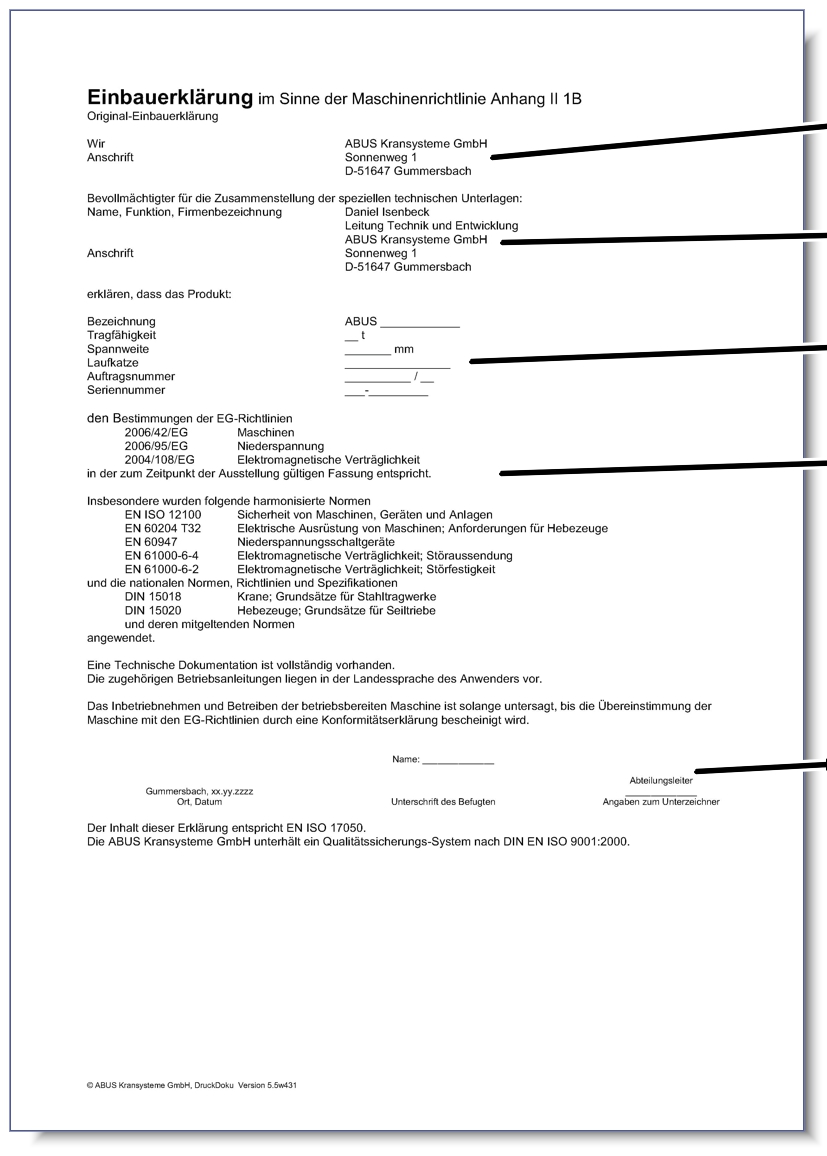
2
3
4
5
- 1: ABUS company address
- 2: Person responsible for putting together the special technical documentation
- 3: Technical specifications identifying the crane
- 4: Information on the fundamental standards underlying development and production.
- 5: Signature of responsible person
ABUS Kransysteme GmbH
Sonnenweg 1
51647 Gummersbach, Germany
Tel. 0049 – 2261 – 37-0
Fax. 0049 – 2261 – 37-247
info@abus-kransysteme.de
Distribution or reproduction of this document, or the utilisation and disclosure of its contents without explicit approval is prohibited. Violations will result in liability for damages. All rights are reserved in regard to the issuing of patents or registered designs.