
AT A GLANCE:
General information
This section applies to anyone who lifts loads using the crane, performs work on the crane, or works nearby.
At the start
Using this product manual
The following symbols are used in this product manual:
- This is an instruction regarding an action and prompts you to perform a work step.
- This is the result of an action and describes what happens on the device.
- This is a list.
Only with...
A section that appears in a box framed by a dashed line is only applicable for certain types, versions or options. The condition to which the section applies is specified at the beginning in the heading “Only with...”.
Instructions for the product manual
Read the product manual through carefully before beginning work. Also be sure to observe additional product manuals for accessories and components.
Afterwards, keep the product manual available in the vicinity of the crane. It must be accessible to all who work with or on the crane.
In the case of reselling or hiring out, always provide the product manual together with the crane.
If equipment is limited, e.g. the drive or main girder connection plate and screws from ABUS are not included, the corresponding sections in the product manual do not apply.
Note regarding the designation “CRANE”
The product manual assumes that the end carriage is used together with a main girder as a crane. As a result, it uses crane specific terms. Other applications are not ruled out by this and the corresponding instructions apply in the same way.
Proper use
The end carriage travels with both wheels on a crane track. It is designed for cranes within the maximum load capacity.
- The end carriage travels in an operating range along a crane track.
- The end carriage must not collide at high speed with other end carriages on the same crane track or at the crane track end stopper. This can be ensured using the crane travel limit switch and anti-collision device.
- This product manual describes the use, installation, removal and maintenance of the components included such as wheels and crane travel drive. It does not include specifications for designing or constructing machines manufactured by you. The end carriages are not a complete machine. For the limits of their use, please refer to the data sheets or other documentation provided.
- The production tolerances for the manufacturing and installation process and the electrical activation are decisive for the risks and usability. For this reason, the crane's manufacturing tolerances as well as the crane track tolerances must be followed. The user is responsible for this during operation. The end carriages have not been subjected to any test load.
- The user must hold welding qualifications of at least level EXC 3 according to DIN EN 1090. Welding on the end carriages may lead to undercuts, which affect anticipated operating times. The user must therefore hold the appropriate qualification for welding dynamically loaded components.
Regulations
The installation has been built and tested according to European standards, rules and regulations applicable at the time of its manufacture. The conventions applied during design and construction are specified in the Declaration of Conformity or the Declaration of Incorporation. The conventions must also be observed for installation, operation, inspection and maintenance, as must the applicable occupational health and safety regulations.
Which provision applies in individual cases will greatly depend on the crane’s use and the national regulations. Review and observe all applicable and current regulations, including the occupational health and safety regulations. Refer also to the Declaration of Conformity or Declaration of Incorporation.
Warranty
- ABUS assumes no liability for damages that were caused by improper use, inadequately trained personnel, incorrect performance of work, nor for any changes, reconstruction or other modification of the crane or crane components which were not approved by ABUS.
- Any warranty claim becomes invalid if components were modified without consent, the crane or crane components were installed, used or serviced in any way other than that described in this product manual, or if parts other than original ABUS replacement parts were used.
- Safe operation of the crane or crane components is only guaranteed if original ABUS replacement parts are used.
The end carriage
End carriage - description of the device
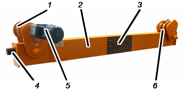
- 1: Wheel, powered
- 2: End carriage
- 3: Joint face
- 4: Safety buffer
- 5: Crane travel drive
- 6: Wheel, not powered
- Performance features
The end carriages:
- The end carriages are fully-automatic, welded U-profiles.
- The end carriages are connected to the main girders using high-tensile bolts, apart from the DLVM on which the end carriages are welded to the main girder.
- The end carriages have safety buffers to prevent damage if the crane runs into the end of the crane track or into another crane.
The travel mechanisms:
- The travel mechanisms hang on the lower flange of the crane track.
- The travel mechanisms consist of two side panels on which the wheels are fitted.
- The travel mechanism can be adjusted to the width of the crane track lower flange using spacer discs.
Transporting the end carriage on a lorry
Observe the following points, amongst others:
- Secure the load in accordance with local regulations.
- Secure all loose parts.
- Secure the side panels against turning.
- Secure the end carriage to the loading area with suitable lifting tackle.
- Cover unpainted surfaces and openings with film and secure with adhesive tape.
Disposing of the end carriage
If the end carriage is to be disposed of:
- Dismantle the end carriage to the extent possible.
- Observe local regulations concerning disposal and recycling.
- Dispose of the individual parts sorted by material in an environmentally sound manner.
- Plastic parts should be recycled with plastic waste.
- Remove brake linings and friction clutch linings and dispose of these multiple components as hazardous waste.
- Remove oil or grease from the crane travel drives and dispose of as a lubricant.
- Sort lines and plug-in connections by material and bring them to a recycling centre.
- Recycle steel structures as scrap metal.
- Dispose of electronic components as scrap electronic parts.

Installing and connecting
This section applies to anyone who works on the crane prior to its use
The end user of the crane is responsible for the proper qualifications of the commissioning personnel.
Examples of qualified persons:
- Persons with comprehensive knowledge from specialist training in engineering and in the electrical systems of cranes.
- Persons with sufficient experience in the operation, installation and maintenance of cranes.
- Persons with comprehensive knowledge regarding the relevant technical rules, directives and safety regulations applicable in the respective country.
- Persons receiving regular training from ABUS.
ABUS assumes no liability for damage due to incorrectly performed commissioning work done by unqualified personnel.
ABUS recommends having the commissioning work performed by the ABUS assembly team.
Installing the crane track
So that the overhead travelling crane travels steadily, smoothly and without great wear and tear, the crane track must be properly installed. Otherwise the overhead travelling crane will travel unsteadily and the wheels will wear out more rapidly.
The design and installation of the crane track must be taken into consideration upon construction of the building and planned together with the architects and structural engineers.
Observe the following points, amongst others:
- The building supports and building beams or concrete supports or concrete girders as well as the brackets should be designed in such a way that the crane track can be welded onto them without difficulty.
- Only have welding work done by companies certified as per EN 1090 EXC-3.
- Monitor welded joints according to this standard.
- Design welded joints to at least quality class B of DIN EN ISO 5817.
- Clean the anchor plates (in the concrete brackets) or the steel brackets (to the building supports) prior to welding. They must be free of dirt, rust, scaling, paint, grease and oil.
- Cut the crane track joints at an angle of 45 degrees. Deburr the cut edges and clean. The gaps between the crane tracks should be as small as possible. The abutting crane track segments should not be misaligned laterally nor offset in height.
- For bolted crane tracks: firmly tighten all bolts with the correct tightening torque.
- Clean the crane tracks. They must be free of grease, oil, paint and dirt.
- Secure the crane track with suitable end stoppers.
- Provide the entire crane track with appropriate corrosion protection (e.g. paint)
Installation overview
The following sections show how the end carriage is installed.
- First the end carriages are bolted to the crane's main girder at the base. See “Bolting on the end carriage”.
- The safety buffers are then installed on the ground. See “Installing the safety buffers”.
- The self-locking nuts are also replaced. See “Replacing self-locking nuts”
- Damage to paintwork is then repaired. See “Repairing damage to paintwork”.
- Then the travel mechanisms are fitted on the crane track. See “Installing the underslung travelling crane under the crane track”.
- As a final step the end carriages and travel mechanisms are tightened with the correct tightening torque. See “Fastening the end carriages tightly”.
Bolting on the end carriage
On EDL and EDK underslung travelling cranes, the end carriages are bolted to the main girder using high-tensile bolts.
Assigning the end carriages
Letter position markers
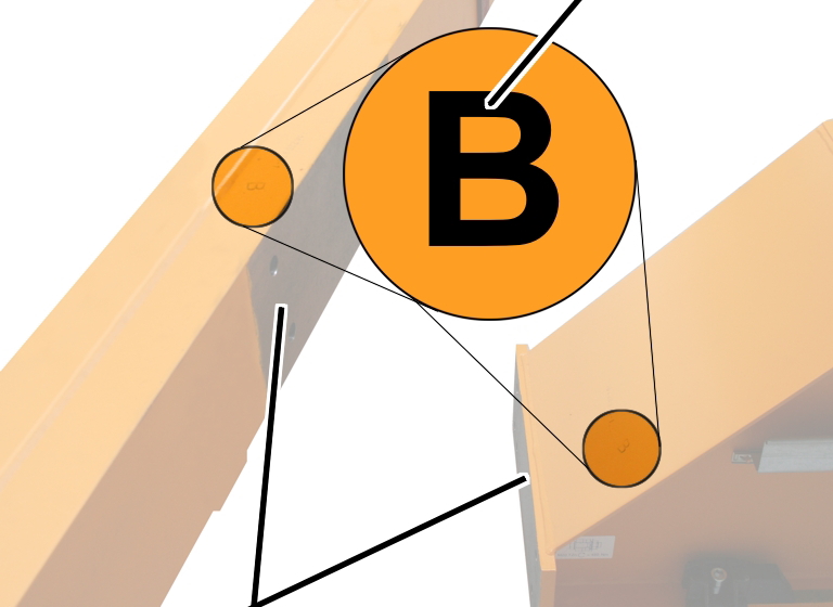
- Look for the letter position markers A and B (for the installation sequence) on the main girders and end carriages.
- Lay both end carriages on the joint faces of the main girder in such a way that the letter position markers match.
Preparing the bolt connection
Residual paint
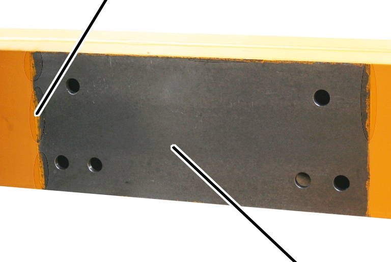
- Thoroughly clean the joint faces on the entire surface. There should not be any rust, dirt, paint or similar impurities on them.
- Lift the end carriages in front of the main girders. The hole patterns must lie exactly over one another.
Checking the high-tensile bolts
- Check the high-tensile bolts. The high-tensile bolts must meet these requirements:
Material |
Size |
Lubrication |
|
|---|---|---|---|
High-tensile bolt (hexagonal) |
10.9 |
M20 |
|
Washer |
C 45 |
HV 21 |
MoS2 |
High-tensile nut (hexagonal) |
10 |
M20 |
MoS2 |
- The high-tensile bolts and mounting plate with high-tensile nuts may only be installed with tightening torque a maximum of twice. If they are installed more than twice with tightening torque, the high-tensile bolts as well as the mounting plates with the high-tensile nuts must be scrapped.
Should it be necessary to loosen the high-tensile bolts during installation, the same high-tensile bolts can be reused a maximum of one more time, otherwise the lubrication will no longer be sufficient!
- The high-tensile nuts and washers must be galvanised and lubricated with MoS2.
- High-tensile bolts which have been installed on a crane for a lengthier period may not be used again.
The end carriages are initially only installed by manually screwing until hand-tight. They are finally firmly screwed (with a tightening torque) only after the crane is hanging under the crane track and the trolley and all other components are installed. By doing this, the main girders can settle and the crane does not hang warped under the crane track. See “Fastening the end carriages tightly”.
High-tensile bolt with washer
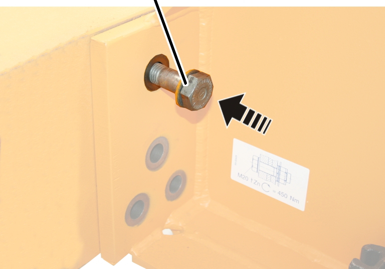
- Place the washers on the high-tensile bolts with the bevel (chamfered edge) to the head of the screw.
- Insert the high-tensile bolts and washers from the outside into the screw holes and screw on so they are somewhat loose.
Sealing the access portal
Access portal
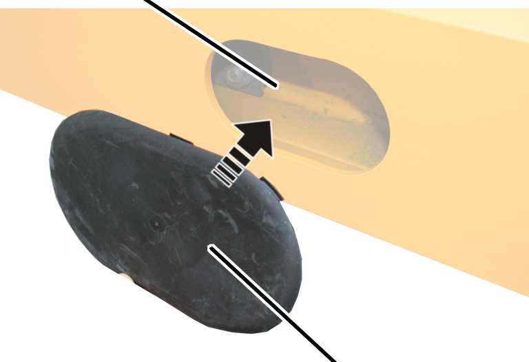
- Seal the access portal with a cap.
Installing the safety buffers
In case the safety buffers are not installed:
Buffer plate
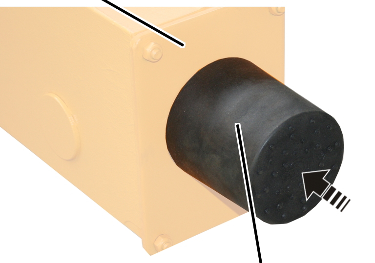
- Screw safety buffers (4x) into the buffer plates. Approx. 30 Nm.
The safety buffer must be in contact with the buffer plate and there must be no gap between them, otherwise the impact will be absorbed by the screw and not by the safety buffer.
Replacing self-locking nuts
Since removing self-locking nuts with an inner plastic ring damages the inner plastic ring, self-locking nuts with an inner plastic ring may only be used once and must be replaced before the underslung travelling crane is installed.
Unscrewing the self-locking nuts
On all side panels:
End carriageSelf-locking nut
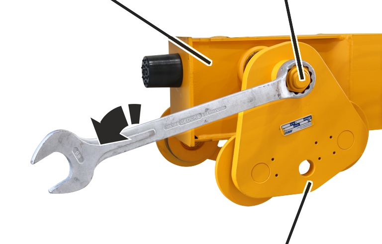
- Unscrew the self-locking nuts from the travel mechanisms.
Screwing on new self-locking nuts
On all side panels:
Spacer discsNew self-locking nut
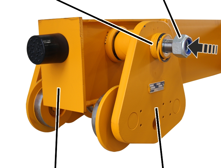
- Loosen spacer discs.
The spacer discs must not stick together.
- Screw on new self-locking nuts.
The nuts must not be tightened because the side panels must be movable for the installation on the crane track.
New self-locking nuts
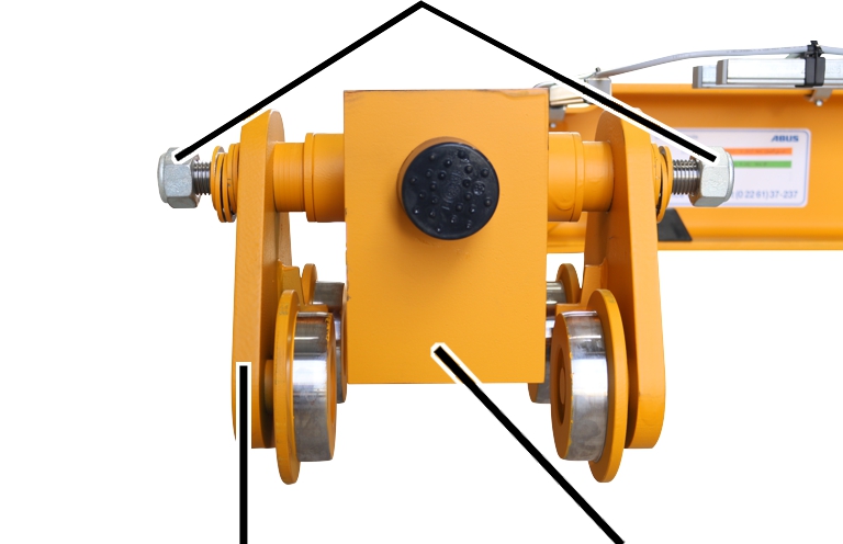
- The self-locking nuts are replaced by new self-locking nuts on all travel mechanisms.
Removing the drive
Both drives are removed to facilitate the installation.
Powered side panel
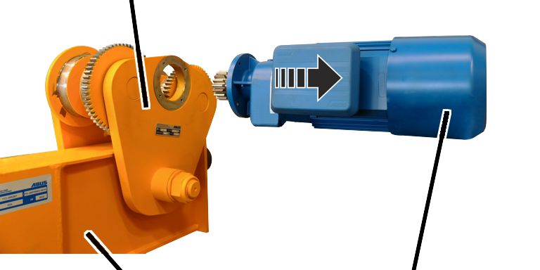
- Release the M6x20 rib screws (4x).
- Pull the drive out of the powered side panel.
Repairing damage to paintwork
- Repair damage to paintwork caused during transportation and installation.
Installing the underslung travelling crane under the crane track
Folding up the side panels
On all side panels:
Crane track
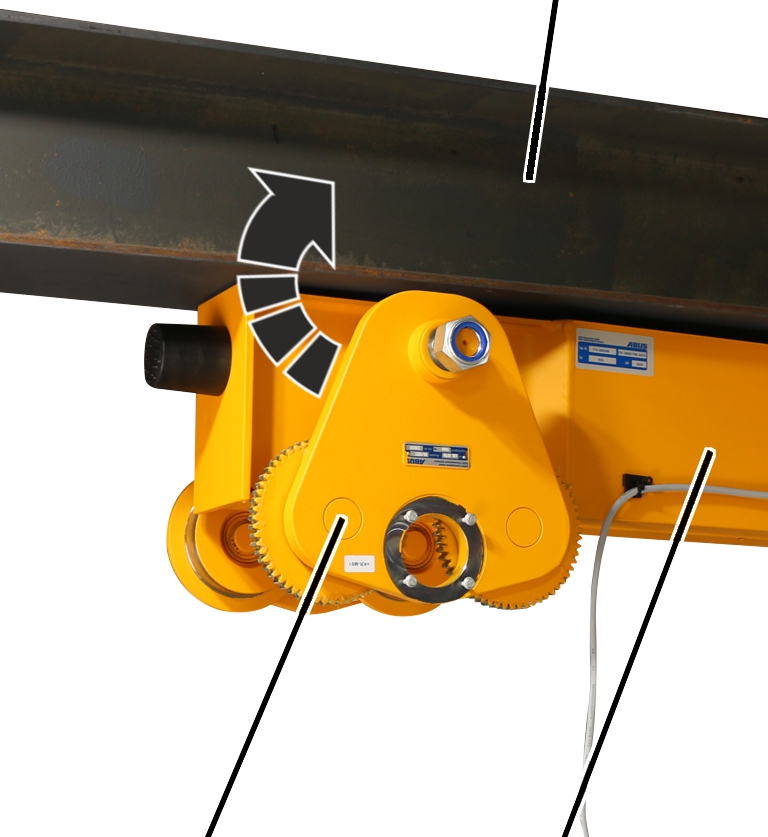
- Fold up the side panels (2x) on both sides of the crane track.
- Push the side panels with the wheels onto the crane track lower flange.
Bolting the side panels into place
On all side panels:
Side panelCrane track
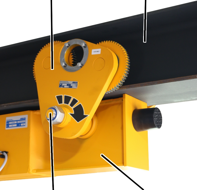
- Bolt the side panels from both sides.
Make sure when doing this that the spacer discs sit flush.
Adjusting the flange width
To adjust the travel mechanism to other flange widths:
New self-locking nuts
- Adjust the discs on the inner or outer side of the side panels.
Caution: The number of discs on both sides of the end carriage must not be modified. A 5 mm thick disc must always be fitted under the nut.
End |
Flange |
Disc position 3 |
Disc position 2 |
Disc position 6 |
|---|---|---|---|---|
DL 80 |
64-125 |
4 |
16 |
|
126-200 |
6 |
18 |
||
201-300 |
4 |
24 |
||
DL 112 |
82-150 |
4 |
18 |
|
151-200 |
4 |
14 |
||
201-300 |
4 |
24 |
||
DL 140 |
98-190 |
4 |
18 |
2 |
200-300 |
4 |
20 |
2 |
Installing the drive
The drives which were removed for the installation process can now be fitted and connected.
Crane track
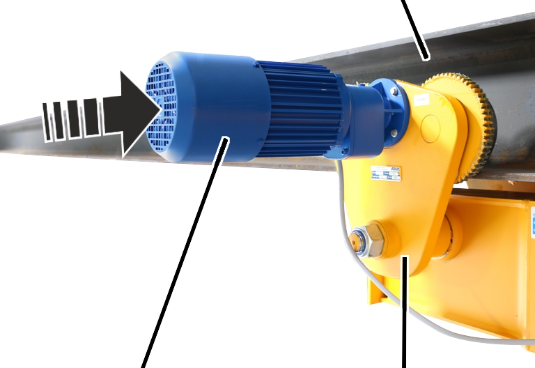
- Slide the drive in the powered side panel.
- Bolt on the drive with the rib screws M6x20 (4x). Tighten with 10 Nm.
Fastening the end carriages tightly
Once all components have been installed, the entire crane has settled as a result of the weight, and the stress is relieved. For this reason, the end carriages can only now be tightened with the tightening torque.
Central high-tensile bolt
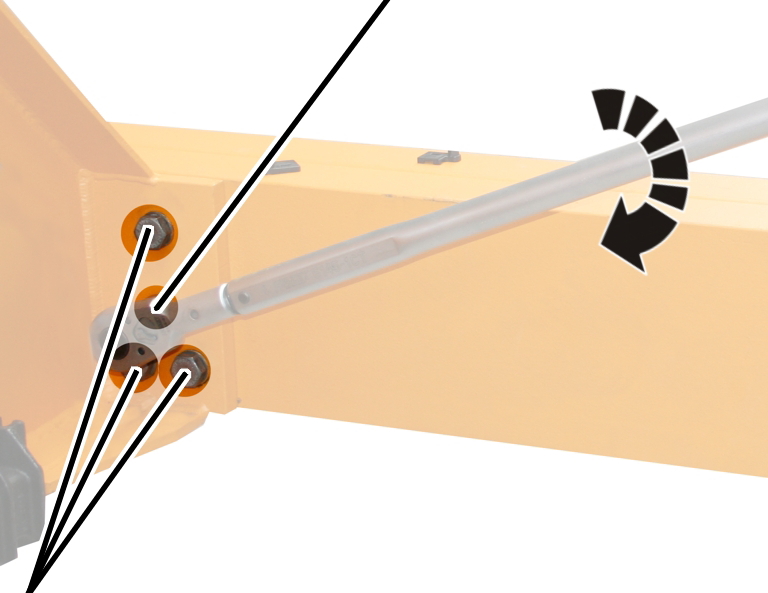
- Only tighten high-tensile bolts with the appropriate torque wrench.
- Do not use an impact wrench.
- Do not tighten high-tensile bolts using turn-of-nut tightening.
- Tighten the central high-tensile bolts on both sides (left and right on the end carriage). Use a torque wrench to 300 Nm.
- Next, tighten the remaining high-tensile bolts, alternating between left and right. Use a torque wrench to 300 Nm.
- Then tighten all high-tensile bolts in the same sequence. Use a torque wrench to 450 Nm.
Note

Mark the high-tensile bolts with a permanent marker with a continuous line from the bolt head over the washer to the plate. This serves as proof that all high-tensile bolts have been tightened with tightening torque.
Bolting the travel mechanisms into place
Once all components have been installed, the entire crane has settled as a result of the weight, and the stress is relieved. For this reason, the travel mechanisms can only now be tightened with the tightening torque.
Side panelCrane track
- Only tighten self-locking nuts with the appropriate torque wrench.
- Do not use an impact wrench.
- Fully tighten the self-locking nut using the table.
Travel mechanism |
Self-locking nut |
Tightening torque |
|---|---|---|
DL 80 |
M20 |
130 Nm |
DL 112 |
M24 |
160 Nm |
DL 140 |
M36 |
220 Nm |
Overview of screw tightening torques
End carriage
- Check the high-tensile bolts. The high-tensile bolts must meet these requirements:
Material |
Size |
Lubrication |
|
|---|---|---|---|
High-tensile bolt (hexagonal) |
10.9 |
M20 |
|
Washer |
C 45 |
HV 21 |
MoS2 |
High-tensile nut (hexagonal) |
10 |
M20 |
MoS2 |
- The high-tensile bolts and mounting plate with high-tensile nuts may only be installed with tightening torque a maximum of twice. If they are installed more than twice with tightening torque, the high-tensile bolts as well as the mounting plates with the high-tensile nuts must be scrapped.
Should it be necessary to loosen the high-tensile bolts during installation, the same high-tensile bolts can be reused a maximum of one more time, otherwise the lubrication will no longer be sufficient!
The high-tensile nuts and washers must be galvanised and lubricated with MoS2.
- High-tensile bolts which have been installed on a crane for a lengthier period may not be used again.
- Initially, only install the end carriages hand-tight.
- Then, lift the entire crane under the crane track and install completely. As a result of the weight, the crane settles and the stress is removed.
- Then tightly screw all high-tensile bolts (with tightening torque).
Central high-tensile bolt
- Only tighten high-tensile bolts with the appropriate torque wrench.
- Do not use an impact wrench.
- Do not tighten high-tensile bolts using turn-of-nut tightening.
- Tighten the central high-tensile bolts on both sides (left and right on the end carriage). Use a torque wrench to 300 Nm.
- Next, tighten the remaining high-tensile bolts, alternating between left and right. Use a torque wrench to 300 Nm.
- Then tighten all high-tensile bolts in the same sequence. Use a torque wrench to 450 Nm.
Travel mechanism
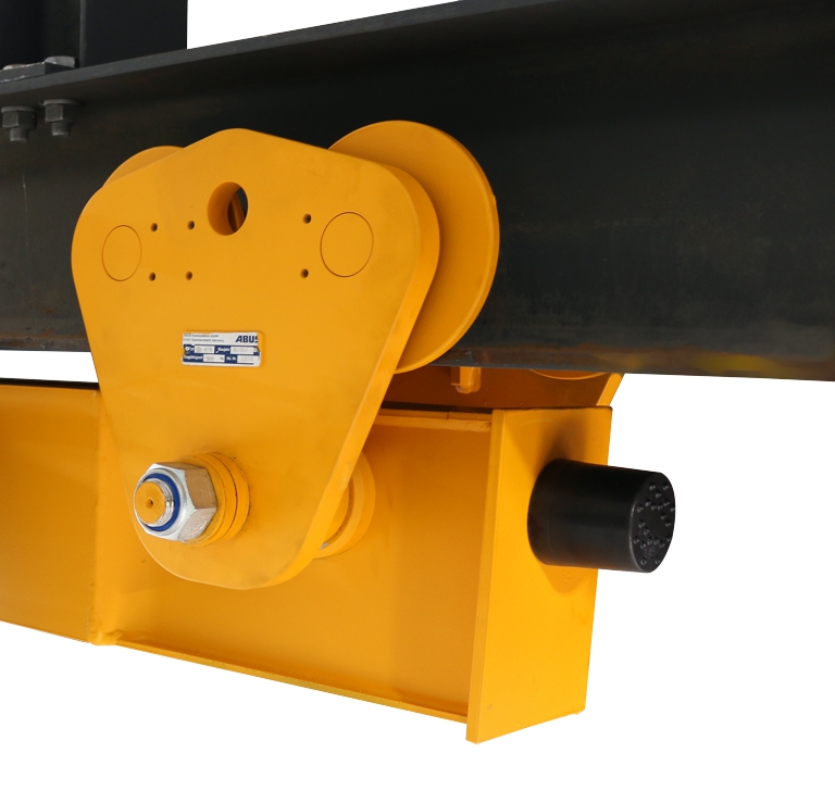
Travel mechanism |
Self-locking nuts |
Number |
Tightening torque |
|---|---|---|---|
DL 80 |
M20 |
8x |
130 Nm |
DL 112 |
M24 |
8x |
160 Nm |
DL 140 |
M36 |
8x |
220 Nm |
Inspection
This section applies to anyone who inspects and accepts the crane in accordance with occupational health and safety requirements
The end carriages must be regularly inspected in order to guarantee safe operation. The end user is responsible for these regular inspections.
At the start
Test intervals
The regular inspection is performed at least once annually.
Under certain conditions, more frequent regular inspections may be necessary. Reasons include:
- Frequent operation at the load capacity
- Working in multiple shifts
- Frequent use
- Dusty or chemically aggressive environment
The end user is responsible for checking the requirements and determining the test intervals. ABUS will gladly assist you if questions arise.
Requirements for the examiner
The end user of the crane is responsible for the proper qualifications of the examiner.
Examples of qualified persons:
- Persons with comprehensive knowledge from specialist training in engineering and in the electrical systems of cranes.
- Persons with sufficient experience in the operation, installation and maintenance of cranes.
- Persons with comprehensive knowledge regarding the relevant technical rules, directives and safety regulations applicable in the respective country.
- Persons receiving regular training from ABUS.
Scope of the test
The qualified person inspecting the crane is responsible for the type and scope of the test.
Overview: Inspecting the crane
In addition to the points described here, all points outlined in the other supplied product manuals must also be checked.
The decision as to whether the crane is in perfect condition may be made only by the person inspecting the crane. Any inadequacies, if found, must be eliminated. The examiner decides whether the crane has to be tested again afterward.
If locally applicable regulations specify further tests, these are likewise to be carried out.
Additionally, at least the following points must be checked:
- Only for braking function or shut-down: check the braking distance of the end carriage in the limit switch range. See “Checking the braking distance”.
- Check the diameter of the wheels. See “Checking the diameter of the driven wheels”.
- Check the condition of the safety buffer. See “Inspecting the condition of the safety buffer”.
Checking the braking distance
Only for braking function or shut-down
The brake on the crane travel drives is worn during operation. This lengthens the braking distance of the crane. The crane may therefore strike the end stopper of the crane track too fast and put excess pressure on the supporting structure (e.g. the building).
- Suspend a load on the load hook which corresponds to the maximum load capacity of the crane.
- Move the crane into the limit switch range.
- Check the braking distance:
For braking function: the crane must run only at low speed just in front of the end stopper.
For shut-down: the crane must come to a standstill just in front of the end stopper.
- If the braking distance is too long: Adjust the brake on the crane travel drive. See the product manual for the crane travel drive.
Checking the diameter of the driven wheels
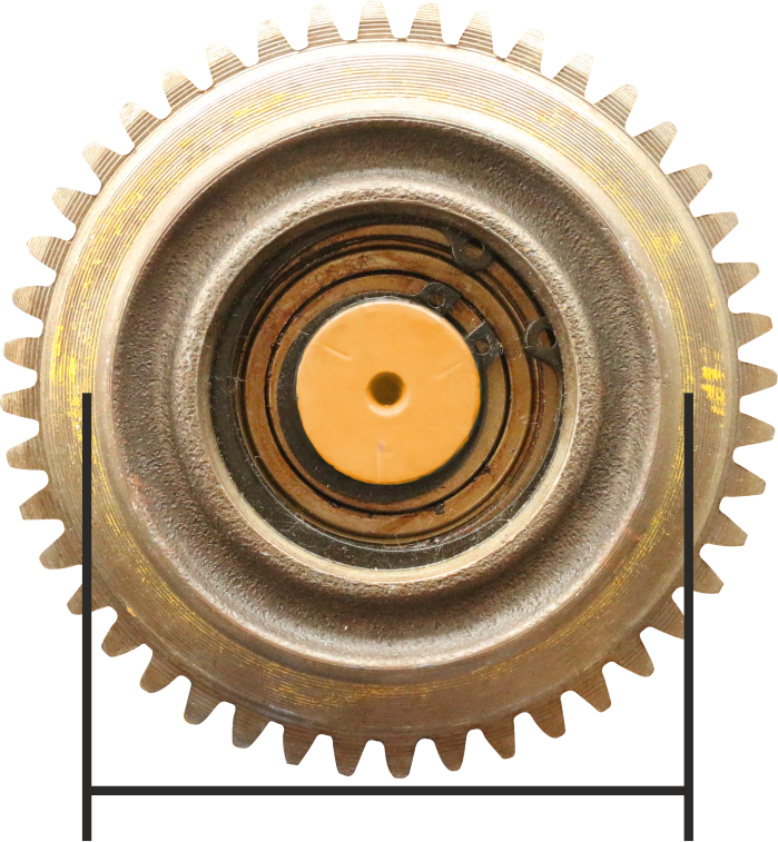
- Measure the diameter of the wheel at multiple points over the width of the wheel.
- The diameter may not be smaller than is specified in the table.
If the diameter is smaller, the wheel must be replaced.
Size |
Maximum permissible wear |
Minimum diameter of wheel |
|---|---|---|
DL 80 |
-3 mm |
77 mm |
DL 112 |
-3 mm |
109 mm |
DL 140 |
-3 mm |
137 mm |
Measuring the difference in diameter
In addition, the driven wheels of the crane must be of uniform diameter so that the crane runs evenly on the crane track.
This means that the permissible deviation in the diameter of opposite-lying driven wheels is limited.
- Determine the difference in diameter of the opposite-lying driven wheels.
The difference in diameter may not be larger than is specified in the table.
If the respective diameters of the wheels deviate from each other by more than this, the wheels must be replaced.
Size |
For cranes subject to lesser loads (formerly crane classification B3) |
For cranes subject to greater loads (formerly crane classification B4) |
|---|---|---|
DL 80 |
2 mm |
1 mm |
DL 112 |
2 mm |
1 mm |
DL 140 |
2 mm |
1 mm |
Checking the diameter of the non-driven wheels
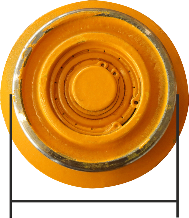
- Measure the diameter of the wheel at multiple points over the width of the wheel.
- The diameter may not be smaller than is specified in the table.
If the diameter is smaller, the wheel must be replaced.
Size |
Maximum permissible wear |
Minimum diameter of wheel |
|---|---|---|
DL 80 |
-3 mm |
77 mm |
DL 112 |
-3 mm |
109 mm |
DL 140 |
-3 mm |
137 mm |
Inspecting the condition of the safety buffer
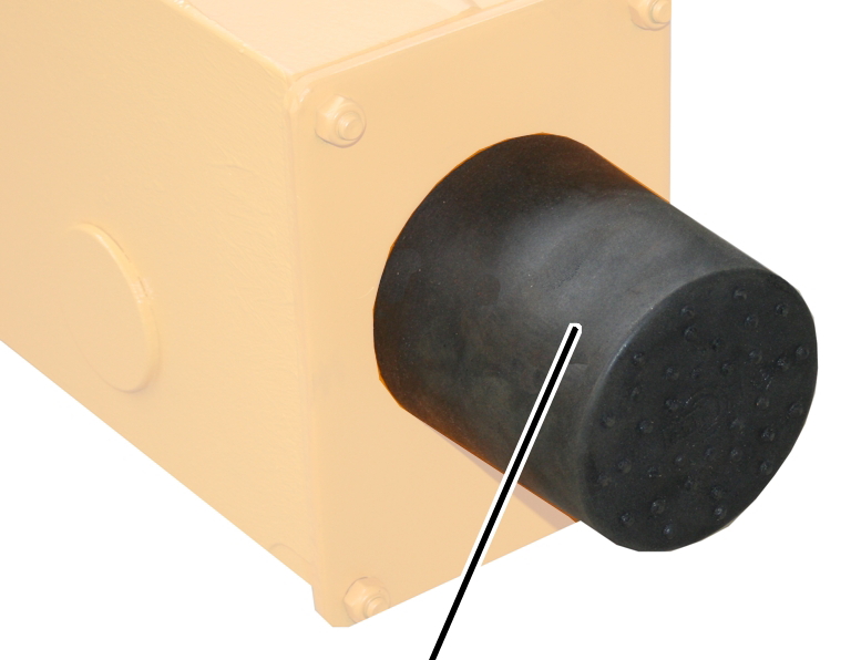
- Check all the safety buffers. The safety buffers must not be porous, pinched, bent or otherwise damaged.
- Check the material of the safety buffers all the way round. The plastic must not be cracked anywhere on the surface.
- Press the safety buffers with your finger. The safety buffers must be able to be pressed in slightly and be formable.
- If any of the safety buffers is damaged in any way whatsoever, replace all the safety buffers on the crane.
- If any of the safety puffers cannot be pressed in, replace all the safety buffers on the crane.
Maintenance
This section applies to anyone who maintains, repairs or modifies the crane.
The end user of the crane is responsible for the selection and proper qualifications of the maintenance personnel.
Examples of qualified persons:
- Persons with comprehensive knowledge from specialist training in engineering and in the electrical systems of cranes.
- Persons with sufficient experience in the operation, installation and maintenance of cranes.
- Persons with comprehensive knowledge regarding the relevant technical rules, directives and safety regulations applicable in the respective country.
- Persons receiving regular training from ABUS.
ABUS assumes no liability for damage due to incorrectly performed maintenance work done by unqualified personnel.
ABUS recommends having the maintenance work performed by ABUS Service.
Use only original ABUS replacement parts. Otherwise, all warranty claims will be rendered invalid.
Instructions regarding safety when performing maintenance work
Please follow the following safety instructions during all repair work on the crane:
- Switch off the mains switch. Secure the switch to ensure it cannot be turned back on accidentally.
- Unplug the mains disconnector plug from the socket on the crane panel. Secure the socket with a padlock to ensure it is not plugged back in accidentally.
- Use suitable lifting platforms and fall protection equipment.
- Adequately cordon off the operating range around the lifting platform.
- Switch off any other cranes using the same crane track or cranes working above or below the crane undergoing maintenance. Secure the switches to ensure they cannot be turned back on accidentally. Otherwise, other cranes could overturn the hoisting platform or crash into the crane undergoing maintenance.
- Notify personnel in the area that maintenance work will be performed.
- Only trained electricians should work on the crane electrical system!
- Even after the emergency stop button has been pressed, life-threatening high voltages are still present in the panels.
Disassembling the wheel
If the wheel is damaged or worn, it must be replaced by a new wheel.
This section shows how to change a non-driven wheel. The procedure to change a driven wheel does not differ significantly from this. Additional work steps are marked with a dashed line.
Preparing the crane
- Comply with occupational health and safety requirements.
- Relieve the load on the wheels.
For a driven wheel only
Removing the drive
CouplingConnector housing
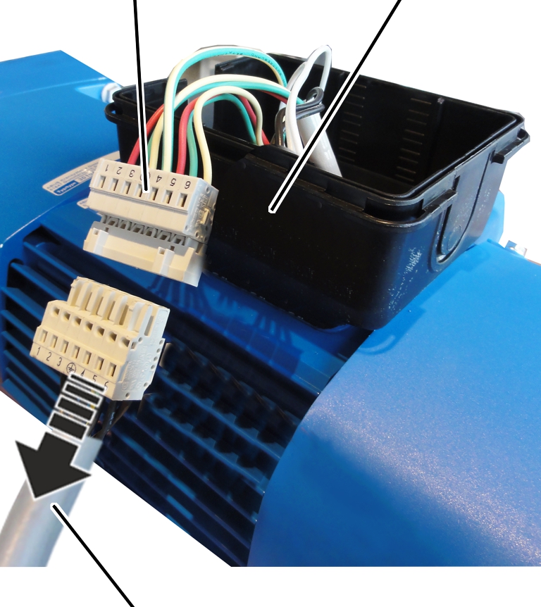
- Open the connector housing to the drive.
- Disconnect the connection cable from the coupler plug.
- Determine the weight of the drive. See the ABUS Drive product manual.
- Secure the drive so that the weight can be held safely and the output shaft will not be subject to load (e.g. insert in round sling).
Crane track
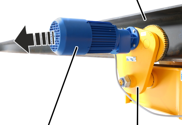
- Release the M6x20 rib screws (4x).
- Pull the drive out of the side panel.
Removing the side panel
Side panelCrane track
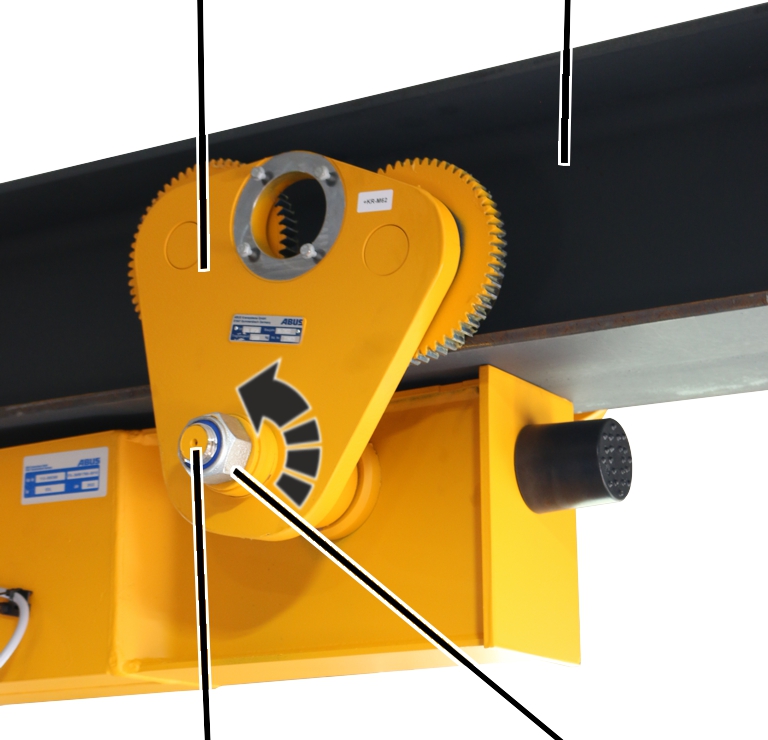
- Unscrew the self-locking nut from the threaded bolt on the side panel.
Spacer discs
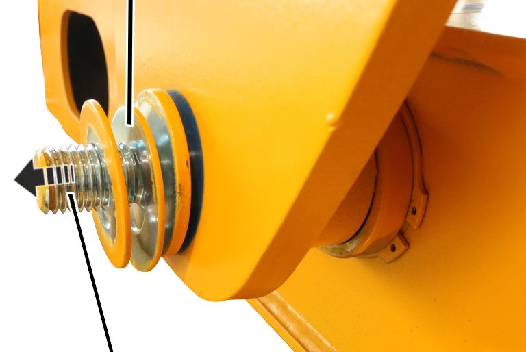
- Take the spacer discs off the threaded bolt.
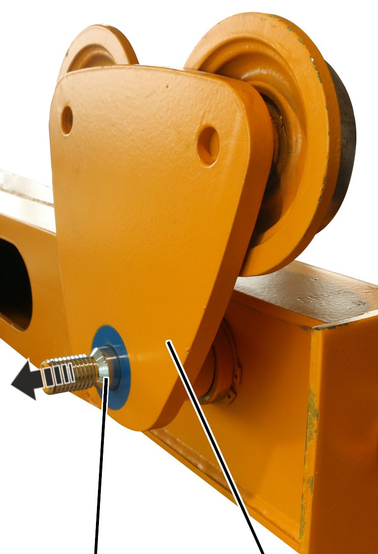
- Take the side panel off the threaded bolt.
Removing the wheel
Pliers
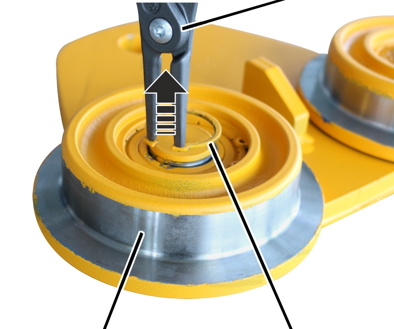
- Lay the side panel on an even surface with wheels facing upward.
- Remove the circlips (2x) from the inner wheels (2x) using pliers.
Bolt
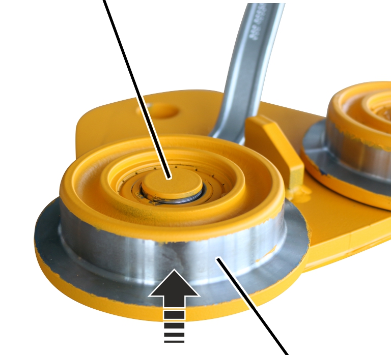
- Remove the wheels (2x) from the bolts with a suitable tool.
Installing the wheel
If the wheel is damaged or worn, it must be replaced by a new wheel.
This section shows how to change a non-driven wheel. The procedure to change a driven wheel does not differ significantly from this. Additional work steps are marked with a dashed line.
Fitting the wheel
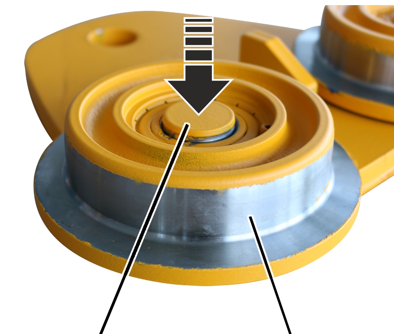
- Hammer the wheels (2x) onto the bolt.
Pliers
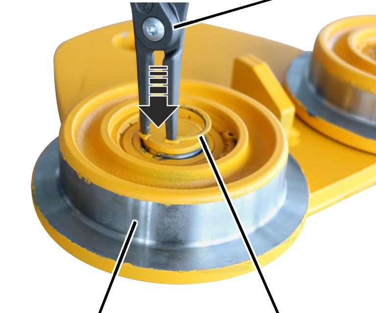
- Insert circlips (2x) into the inner wheels using pliers.
Fitting the side panel
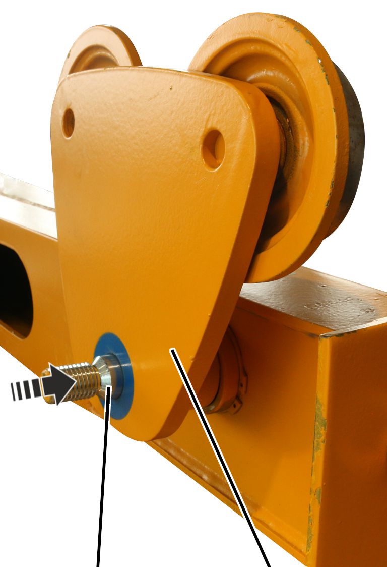
- Push the side panel onto the threaded bolt on the end carriage.
Spacer discs
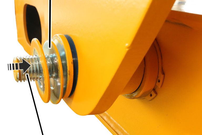
- Slide the spacer discs onto the threaded bolt.
Note
The number of spacer discs determines the flange width on the travel mechanism.
The difference between the spacer discs on the left and right side of the threaded bolt on the end carriage must not exceed 2.5 mm. That is the equivalent of 1 thin spacer disc.
Side panelCrane track
- Tighten the self-locking nut.
Make sure when doing this that the spacer discs sit flush.
Travel mechanism |
Self-locking nut |
Tightening torque |
|---|---|---|
DL 80 |
M20 |
130 Nm |
DL 112 |
M24 |
160 Nm |
DL 140 |
M36 |
220 Nm |
For a driven wheel only
Installing the drive
Crane track
- Slide the drive in the powered side panel.
- Bolt on the drive with the rib screws M6x20 (4x). Tighten to 10 Nm.
Lubricating the gear rim
Drive
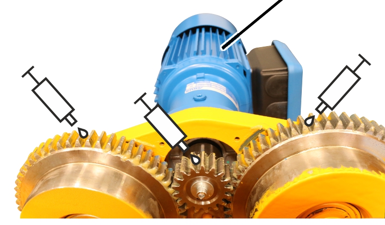
- Lubricate all three gear rims. Apply a liberal coating of lubricant using a brush.
Recommendation: Multi-purpose grease “High-Lub LT1 EP”, item number 317880.
Alternative: Multi-purpose grease “High-Lub”, item number 318490 (cartridge with 400 g).
Screwing with tightening torque
Trolley
Travel mechanism |
Self-locking nuts |
Number |
Tightening torque |
|---|---|---|---|
DL 80 |
M20 |
8x |
130 Nm |
DL 112 |
M24 |
8x |
160 Nm |
DL 140 |
M36 |
8x |
220 Nm |
Drive
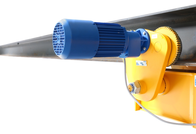
Size |
Type and size |
Number |
Tightening torque |
|---|---|---|---|
DL 80/112 |
Rib screw M6x20 |
4x |
10 Nm |
DL 140 |
Rib screw M6x20 |
4x |
10 Nm |
Lubricants
Drive wheel gear rims
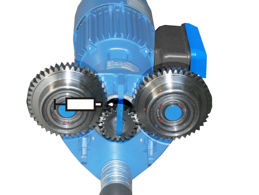
On-site lubrication with “High-Lub LT1 EP”, ABUS item number 318490.
Lubrication ex works with “High-Lub LT1 EP”, ABUS item number 317880.
Quantity: Apply a liberal coating of lubricant using a brush.
Alternative:
- “High-Lub °318490 (cartridge with 400 g)”
Lubricate the gear rim for:
- Removing and fitting the drive
- General overhaul
- Regularly check that the gear rims are completely lubricated and the lubricant is not dirty.
- If the lubricant is dirty: Clean the gear rims and reapply lubricant.
ABUS Service
Only in Germany
- If available, have the product number, serial number and customer number handy.
- Call the ABUS Service Centre:
- Phone: +49-2261-37-237
- If calling outside the usual business hours, leave a message on the answering machine.
- ABUS Service will return your call promptly.
- If necessary, send a description of the problem by fax or e-mail:
- Fax: +49-2261-37-265
- E-mail: service@abus-kransysteme.de
Only outside Germany
- Call the local ABUS branch or crane service partner.
Your local ABUS branch or crane service partner will provide details of contact data, contacts and availability.