The following sections show how the push trolley HF and electric trolley EF are installed
─ The trolley is first pre-assembled on the floor and adapted to the flange of the I-beam. See Pre-assembling the trolley.
─ Then the trolley is mounted on the I-beam, see Mounting the trolley on the I-beam.
─ Finally, the power carrier is installed. See Installing the power carrier.
─ If necessary, the travel limit switch is then installed. See Installing the travel limit switch.
─ Then, if necessary, the buffer rods are fixed to the other trolleys. See Mounting the buffer rods.
─ The electrical connection of the trolley will differ according to whether it is to be connected to an ABUS crane installation (see Connecting the drive to an ABUS crane) or a non-ABUS installation (see Connecting the drive to crane installations not made by ABUS).
─ Finally, the connection cables are laid properly. See Laying the connection cable.
|
|
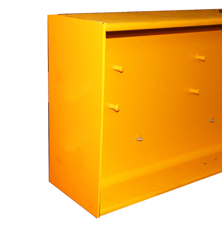
The following work steps describe how the trolley is to be installed on an I-beam which is not freely accessible at the front and rear (welded end plate, building wall etc.).
If one of the two ends of the I-beam is freely accessible, the installation will be slightly easier: The side panels can then be bolted directly to the floor (observe tightening torques!) and the trolley can be pushed onto the lower flange from the open side.