Read the flange allowance FZ
listed in the table according to the trolley type (HF or EF) and size.
Read the flange allowance FZ
listed in the table according to the trolley type (HF or EF) and size.The following work steps can be performed on the floor.
The track gauge of the trolley is adapted for the width of the flange using multiple distance rings.
Read the flange allowance FZ
listed in the table according to the trolley type (HF or EF) and size.
|
Size |
FZ for HF [mm] |
FZ for EF [mm] |
|
3 |
25 mm |
- |
|
6 |
25 mm |
- |
|
14 |
23 mm |
35 mm |
|
22 |
30 mm |
41 mm |
|
36 |
30 mm |
41 mm |
|
50 |
62 mm |
62 mm |
|
|
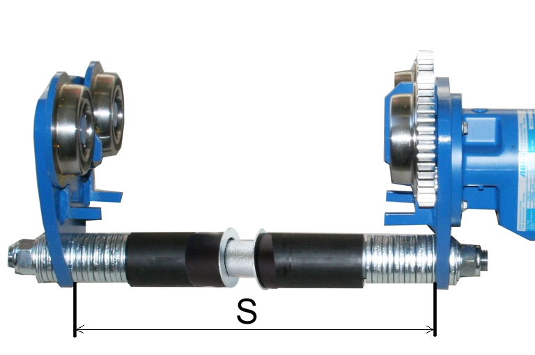
Track gauge S = flange width F + flange allowance FZ
|
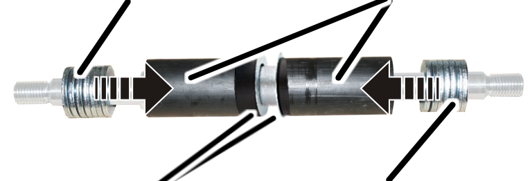
Distance rings |
Bushes |
|
| |
|
Distance rings |
Distance rings |
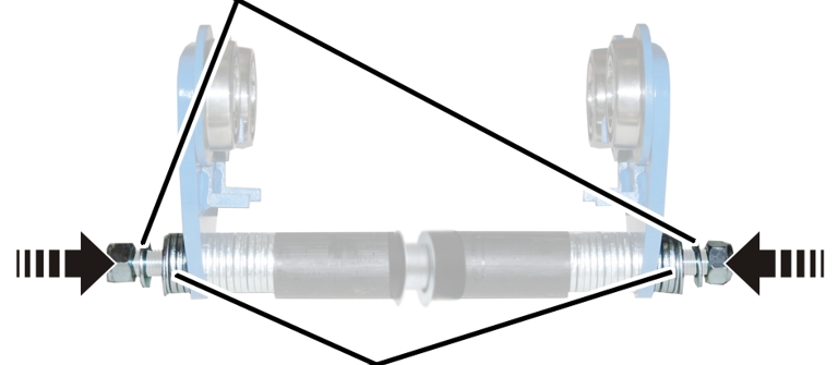
Slide the bushes (2x) onto the
travelling gear bolt with distance rings (2x) in the centre.
Slide the 2.5 mm and 5 mm
distance rings on the travelling gear bolt identically on the left and right
until the calculated track gauge S is reached.
There must always be the same number of distance rings of the same thickness on the left and right. This will ensure that the chain hoist rests centrally under the trolley and distributes its weight evenly on all wheels.
Leave at least one spare 5 mm distance ring for each side and do not use it at this point.
|
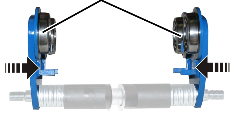
Side panels |
|
|
Slide both side panels, left and
right, onto the travelling gear bolt.
|
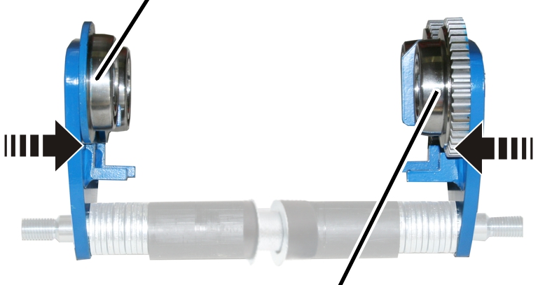
Side panel, not powered |
| |
|
| ||
|
|
Side panel, powered | |
Slide the non-powered side panel
and powered side panel (wheels with gear rim) on the left and right onto the
travelling gear bolt.
|
Washer |
|
|
| |
|
Distance ring(s) | |
If available: Slide the
remaining 2.5 mm and 5 mm distance rings onto the travelling gear bolt
identically on the left and right.
Slide on at least one 5 mm
distance ring (left over from the adjustment of the travelling gear bolt) on
each side.
Slide on one washer each on the
left and right sides.
Turn the self-locking nuts each
several turns on the travelling gear bolt. The side panels should still allow
themselves to be tipped and rotated.
This work step applies only to electric trolleys EF 14 and EF 22 with narrow flange widths and lightweight chain hoists.
Small electric trolleys with narrow flange widths and lightweight chain hoists require a counterweight. Otherwise, the weight of the motor would place an uneven load on the wheels.
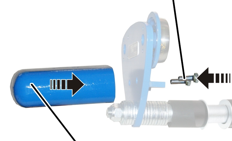
If a counterweight was included in the delivery:
|
|
Hexagon head screw M10x30 | |
|
| ||
|
Counterweight |
| |
Hold the counterweight to the
non-powered side panel.
Fasten the counterweight with
two hexagon head screws M10x30 until hand-tight.