Only with electric trolley EF
If the drive is to be connected to an installation not manufactured by ABUS, continue reading. If the drive is to be connected to an ABUS crane installation, see Connecting the drive to an ABUS crane.
─ The drive is connected in the connector housing on the drive using a plug-in connection.
The plug-in connection is available as a set, AN 105581.
─ When connecting, ensure that the rectifier for the brake is provided with alternating current in the connector housing with the drive switched on. This will require a jumper in the circuitry.
─ The drive can be connected three ways: pole-changeable (high and low speeds), with only one of the two speeds, and through a frequency converter.
Checking the mains supply
 Compare the operating voltage
and frequency range on the type plate with the mains voltage and frequency of
the local grid.
Compare the operating voltage
and frequency range on the type plate with the mains voltage and frequency of
the local grid.
Connecting the drive
Low and high speed:
|
Jumper between 1W and 2W | |||
|
| |||
|
Low |
High |
Star points** |
Brake |
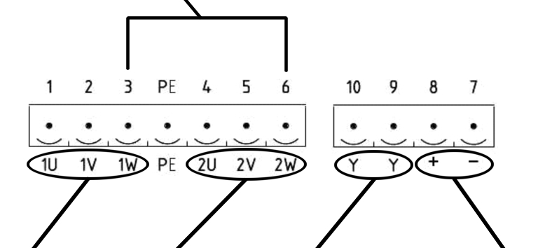
Connect protective
conductor.
Connect contacts 1, 2 and 3 for
low speed.
Connect contacts 4, 5 and 6 for
high speed.
Provide jumper between contacts
3 and 6. This provides the rectifier power supply for the brake. This
provides the rectifier power supply for the brake.
Low speed only:
|
Jumper between 1W and 2W | |||
|
| |||
|
Low |
|
Star points*** |
Brake |
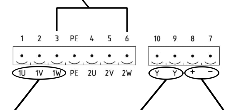
Connect protective
conductor.
Connect contacts 1, 2 and 3 for
low speed.
Provide jumper between contacts
3 and 6. This provides the rectifier power supply for the brake. This
provides the rectifier power supply for the brake.
High speed only:
|
Jumper between 1W and 2W | |||
|
| |||
|
|
High |
Star points |
Brake |
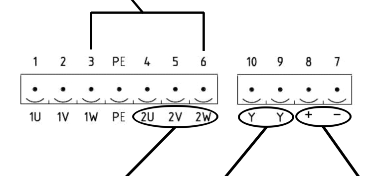
Connect protective
conductor.
Connect contacts 4, 5 and 6 for
high speed.
Provide jumper between contacts
3 and 6. This provides the rectifier power supply for the brake. This
provides the rectifier power supply for the brake.
Motor control through frequency converter:
|
| |
|
High |
Brake |
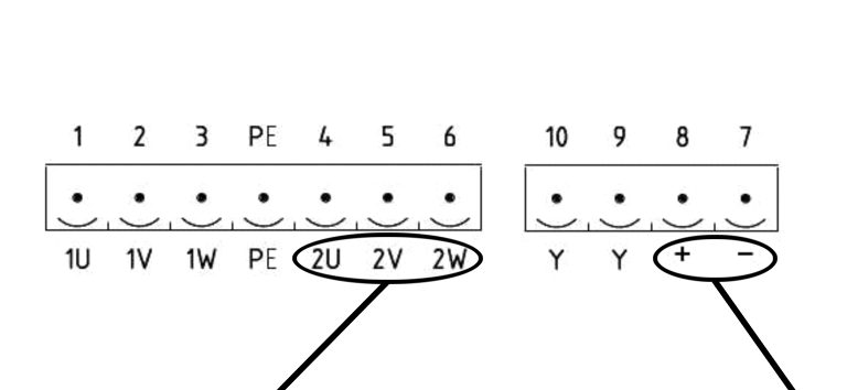
Connect protective
conductor.
Connect contacts 4, 5 and 6 to
the frequency converter for high speed.
Connect contacts 7 and 8 for the
brake control. The electrical circuit must be open at a frequency of 0 Hz.
Brake performance data:
─ Drive EF 80 / 112: 195 VDC, 21 W
─ Drive EF 140: 195 VDC, 25 W