Lift-off prevention device
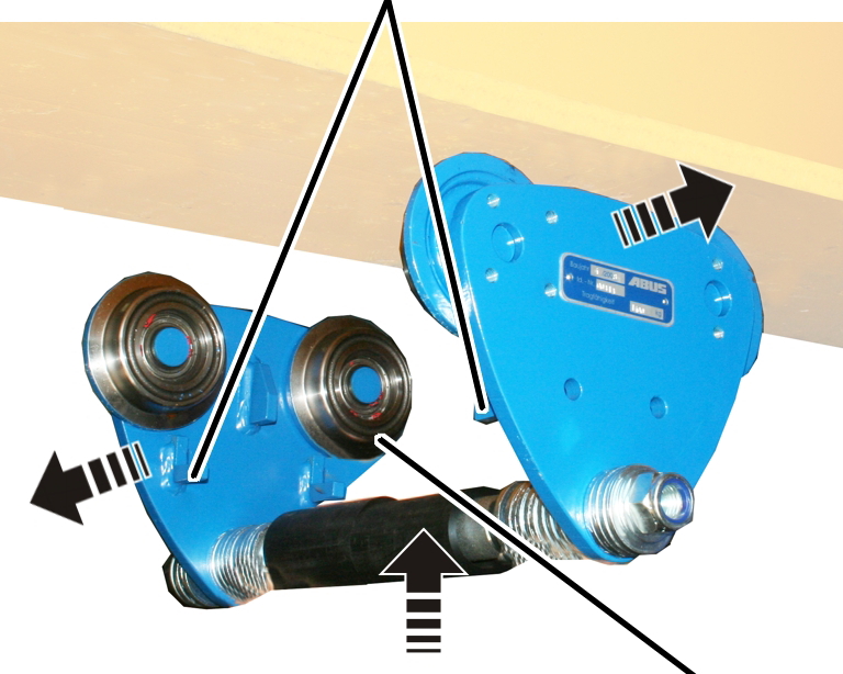
Wheels
|
Lift-off prevention device | |
|
| |
|
|
Wheels |
 Only with electric trolley
EF:
Only with electric trolley
EF:
Turn the trolley so that the drive (side panel with gear rims on the wheels) lies on the side opposite to the power supply and lift the trolley under the beam.
The drive must also be on the outer side of the curve. The power supply must therefore lie on the inner side of the curve.
Only with push trolley HF: The
side panels are identical. For this reason it makes no difference which way
round the trolley is mounted.
Press or turn the side panels
apart at the top.
Slide the trolley with the
wheels on the flange and the lift-off prevention device under the flange.
Fold the side panels together
and secure them against slipping.
Note:
If the two side panels cannot be folded out or turned far enough, remove one side panel completely and slide the trolley onto the flange in two parts.
|
|
Danger from falling suspended load! If the tolerance of the track gauge is exceeded, the trolley, together with chain hoist and load, could slip from the beam and seriously or fatally injure someone. Before installing, check the tolerance precisely. |
|
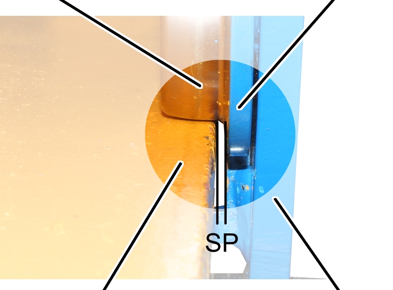
Wheel |
Wheel flange | |
|
| ||
|
Flange |
Side panel | |
Measure the clearance between
wheel flange and rail SP (the distance between the rail flange and the wheel
flange) on both sides of the trolley. The measured value may not be larger than
2 mm on either side.
|
|
|
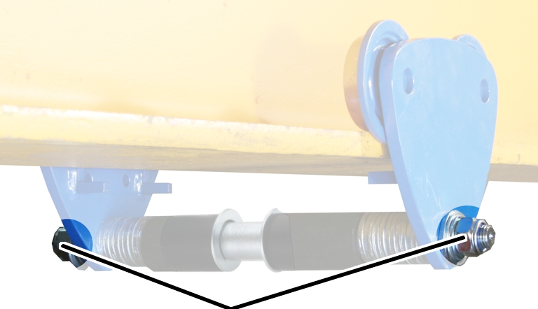
Self-locking nut |
Tighten the self-locking nut.
|
Size |
Type |
Tightening torque |
|
HF 3 |
M12 |
70 Nm |
|
HF 6 |
M16 |
90 Nm |
|
HF 14 EF 14 |
M20 |
130 Nm |
|
HF 22 EF 22 |
M24 |
160 Nm |
|
HF 36 EF 36 |
M30 |
200 Nm |
|
EF 50 |
M36 |
300 Nm |
|
| ||
|
| ||
|
|
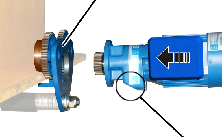
Flattened gear side | |
Only for drive with helical gear
unit: Align the drive with the flattened gear side facing down.
Only for drive with planetary
gear unit: The drive can be positioned either way.
Slide the drive in the powered side
panel.
Bolt on the drive with the rib
screws M6x20 (4x). Tightening torque 10 Nm.
|
|
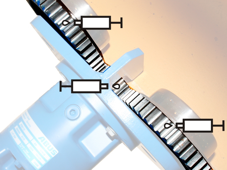
Lubricate all three gear rims.
Lubricant: “High-Lub LT1 EP”. For details, see Lubricants.
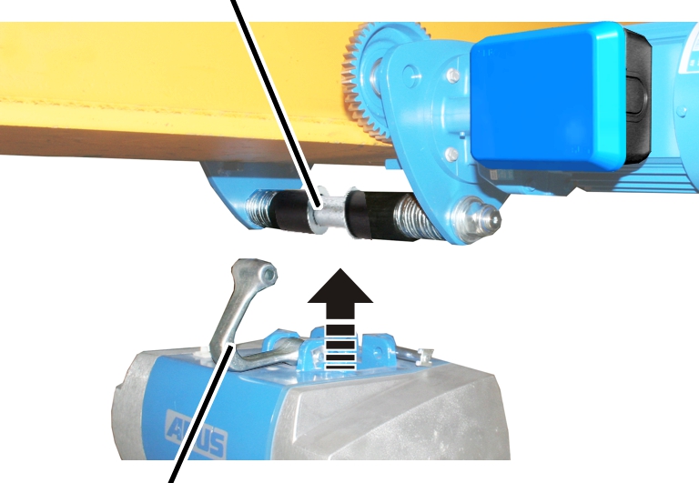
The chain hoist can now be suspended on the travelling gear bolt with the fold-out suspension bracket. Be sure to read and observe the product manual of the chain hoist!
|
Travelling gear bolt |
| |
|
| ||
|
Suspension bracket |
| |
Attach the chain hoist with
folded-out suspension bracket under the travelling gear bolt.
Fold the suspension bracket over
the travelling gear bolt.
Both distance rings should sit to the left and right of the suspension bracket.
Insert the bolt in the
suspension bracket and press on the SL safety clip.