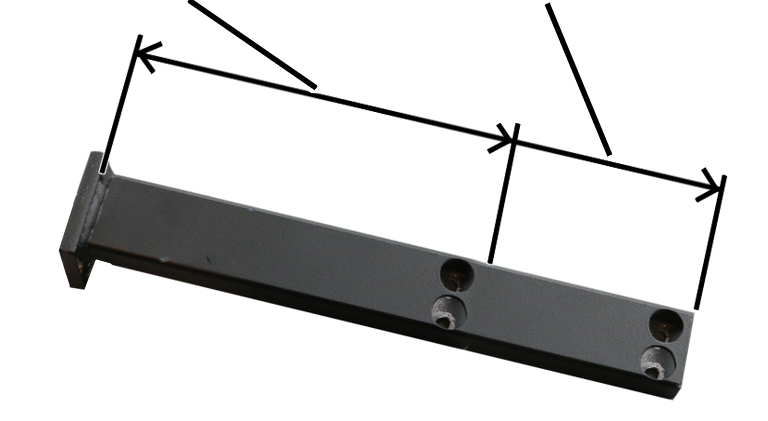
Mount
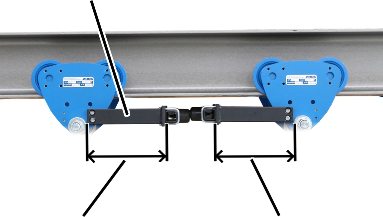
Distance on left
Distance on right
The buffer rods prevent two trolleys (e.g. from two trolleys on one crane) from running into each other. They are made up of a metal frame on the side panels of the trolley and one rubber buffer each.
Two different lengths are possible for the buffer rod mounts on the two trolleys depending on the trolley and chain hoist combination.
|
Mount |
|
|
| |
|
Distance on left |
Distance on right |
 Read off the required trolley
and chain hoist combination from the table.
Read off the required trolley
and chain hoist combination from the table.
|
Trolley |
Chain hoist combination Left / right |
Mount on left |
Mount on right |
|
HF 3 |
GMC / GMC |
192 |
192 |
|
GMC / GM2 |
192 |
192 | |
|
GMC / GM4 |
192 |
192 | |
|
GM2 / GM2 |
192 |
192 | |
|
GM2 / GM4 |
192 |
192 | |
|
GM4 / GM4 |
192 |
192 | |
|
HF 6 |
GM2 / GM2 |
192 |
192 |
|
GM2 / GM4 |
192 |
192 | |
|
GM4 / GM4 |
192 |
192 |
|
Trolley |
Chain hoist combination Left / right |
Mount on left |
Mount on right |
|
HF 14 |
GM4 / GM4 |
192 |
284 |
|
GM4 / GM6 |
192 |
284 | |
|
GM6 / GM6 |
284 |
284 | |
|
HF 22 |
GM6 / GM6 |
192 |
284 |
|
GM6 / GM8 |
192 |
284 | |
|
GM8 / GM8 |
284 |
284 | |
|
HF 36 |
GM6 / GM6 |
192 |
192 |
|
GM6 / GM8 |
192 |
284 | |
|
GM8 / GM8 |
284 |
284 | |
|
EF 50 |
GM8 / GM8 |
192 |
284 |
At all four mounts:
|
Distance for 284 mm length | |
|
| |
Depending on the previously
determined length, prepare two mounts each for "distance left" and "distance
right".
─ Saw the mounts off at a right angle in the appropriate position for 192 mm length.
─ Leave the mounts at their full length for 284 mm length.
Deburr the sawed edge if necessary.
On both sides of the trolley and on both trolleys:
Hold the mounting plate against
the hole pattern on the trolley side panel.
Screw on the mounting plate with
rib screws M6x12. Tighten to 19 Nm.
|
| |
|
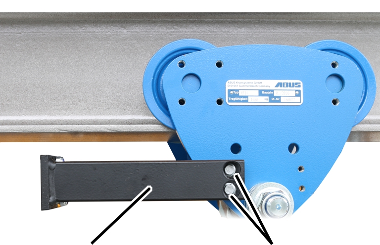
Mount |
Rib screws M6x12 |
Hold the mount against the hole
pattern on the trolley side panel (or the mounting plate).
Tighten the mount using rib
screws M6x12 (2x each), only hand-tight at first.
|
| |
|
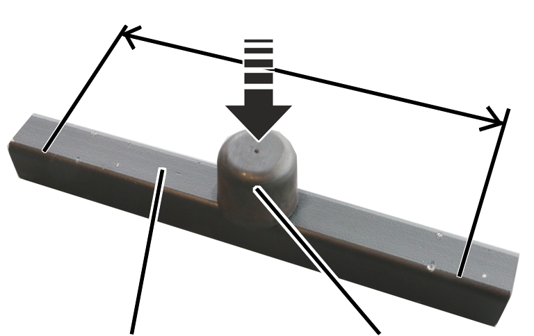
Buffer rod |
Rubber buffer |
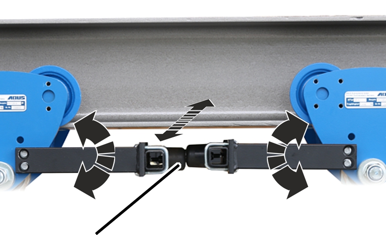
Shorten the buffer rod evenly on
both sides in accordance with the flange width.
The rubber buffer must be exactly in the centre of the buffer rod later.
Screw the rubber buffer to the
buffer rod using the self-locking nut M8. Tighten to 19 Nm.
|
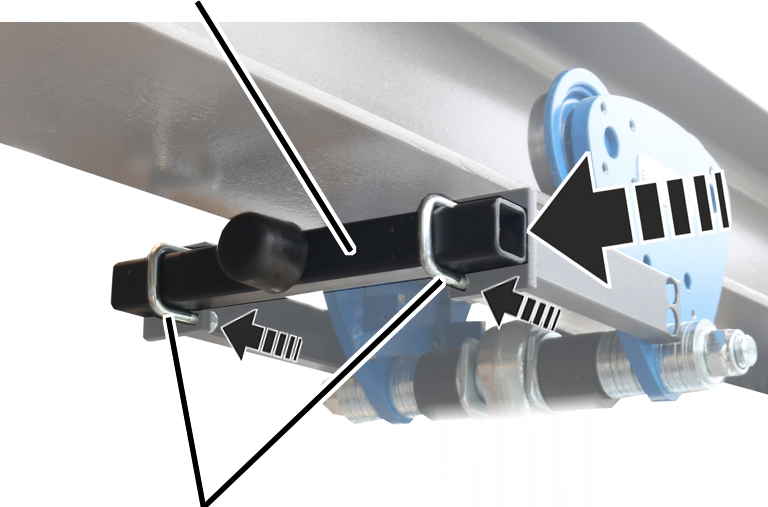
Buffer rod |
|
|
| |
|
Threaded bracket |
|
First screw the threaded bracket
loosely to the mount using the self-locking nut M8.
Slide the buffer rod into the
threaded bracket on both sides.
|
| |
|
Rubber buffer |
|
Align the buffer rods to both
trolleys. The rubber buffers must lie exactly over one another.
Tighten the rib screws M6x12 (2x
each) on the side panel. 19 Nm.
Screw the threaded bracket
tight. 25 Nm.