|
|
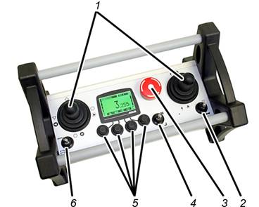
─ 1: Joystick:
Operating the crane. See Lifting and lowering, trolley travel, crane travel.
─ 2: HORN and CHANNEL CHANGE flip switch:
Press towards HORN: activate the horn. See Horns.
Press towards CHANNEL CHANGE: Searches for a different, free radio channel and switches to it. See Changing the radio channel.
─ 3. Stop button:
Triggers an emergency stop on the crane. See Emergency stop.
Switching transmitter on and off. See Checking, switching on and releasing prior to beginning work and Logging out and switching off the transmitter.
─ 4: MENU and ENTER flip switch:
Press towards MENU: Opens the main menu or closes it. See Opening and closing the menu and menu items.
Press towards ENTER: Opens menu items and confirms values. See Using the ABURemote menu.
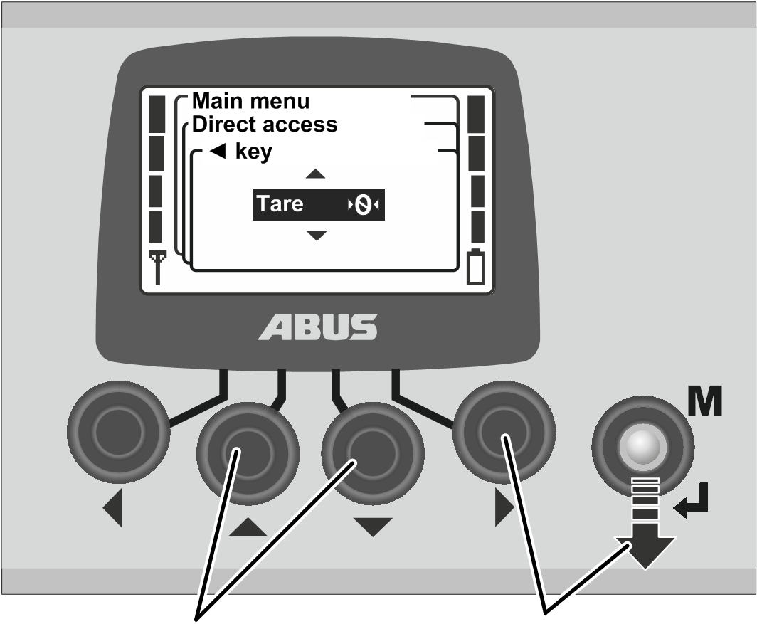
─ 5: Arrow buttons / Direct access buttons:
In the menu: Menu operation. See Using the ABURemote menu.
In “Normal” operating mode: Can be assigned as direct access buttons with additional crane functions (e.g. tare, crane lighting). See Setting the direct access buttons.
─ 6: Flip switches “Select trolley” and “Select crane”:
Press towards “Select crane”: Selects one of the two cranes or both cranes. See Operating cranes in tandem operation.
Press towards “Select trolley”: Selects one of the two trolleys or both trolleys. See Operating a crane with two trolleys.
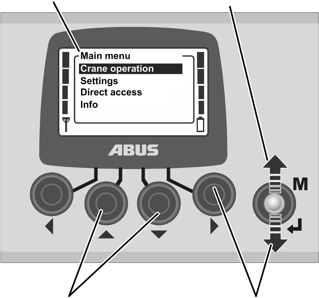
Many functions and settings can be conveniently selected from the menu.
To open the menu and menu items:
|
Main menu |
MENU |
|
| |
|
UP and DOWN |
RIGHT and ENTER |
● The main menu is shown in the display.
 Select the desired menu
item using the UP and DOWN arrow buttons.
Select the desired menu
item using the UP and DOWN arrow buttons.
● The menu item selected is backlit in black.
Open the selected menu
item using the RIGHT arrow button or ENTER.
|
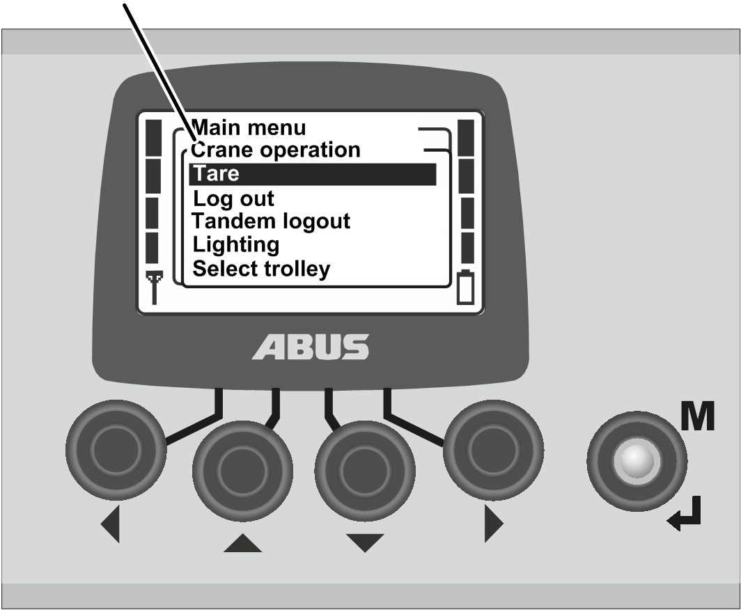
Submenu |
|
|
| |
● The opened menu item or a submenu appears in the display.
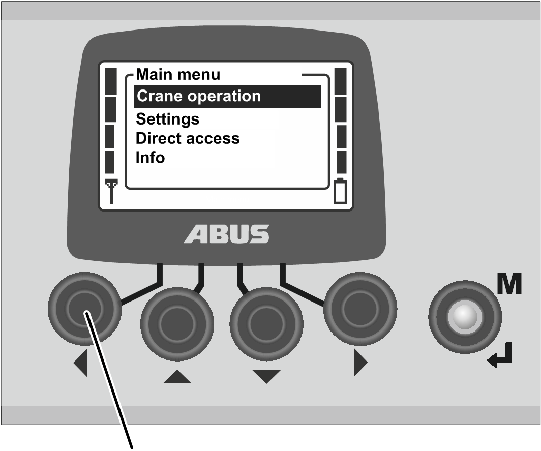
To switch to the previous menu or return to the main menu:
|
| |
|
LEFT |
|
● The previous menu or main menu appears on the display again.
To quit the menu:
|
|
MENU |
|
| |
Press MENU.
Or:
Press the LEFT arrow button several times.
● The transmitter closes the menu and returns to the previous operating mode.
Values can be selected or set for many functions.
|
| |
|
UP and DOWN |
RIGHT and ENTER |
● A window with the currently set or selected value appears on the display.
If values can be selected
or set at several places on the display: Select a place using the RIGHT and LEFT
arrow buttons.
The place selected is backlit in black.
Select or set the required
value using the UP and DOWN arrow buttons.
Confirm the selected or
set value using the RIGHT arrow button or using ENTER.
● The value selected or set is now saved.
If the value does not need to be changed:
Either:
Use MENU to quit the menu.
Or:
Use the LEFT arrow button to change back to the previous menu.
Error codes or other information appear in the form of messages.
|
Message |
|
|
| |
|
LEFT and RIGHT |
ENTER |
Press ENTER.
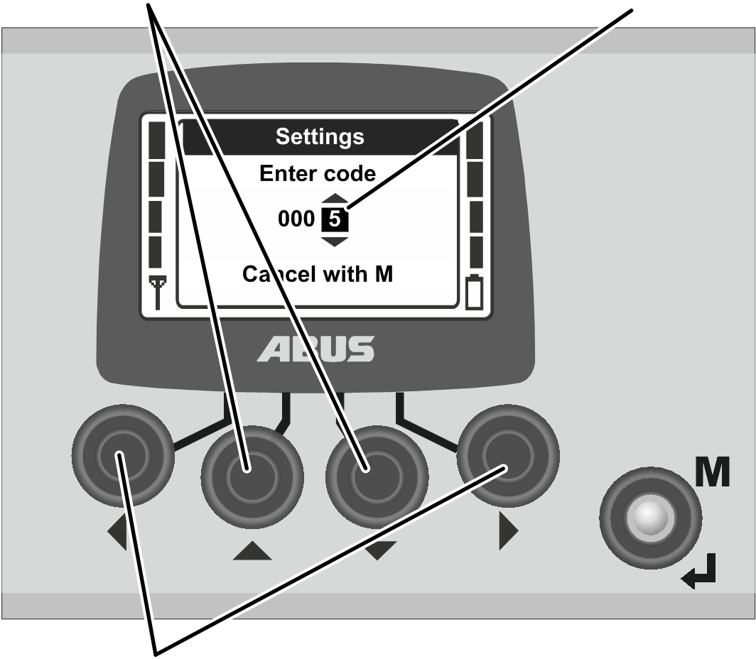
A number of menus are protected by a code to prevent any unintentional changes. Furthermore, the entire transmitter as well as certain functions can be protected by a PIN.
|
UP and DOWN |
Code 0005 |
|
| |
|
LEFT and RIGHT |
|
Select the digits to be
set using the LEFT and RIGHT arrow buttons.
● The digit selected is backlit in black.
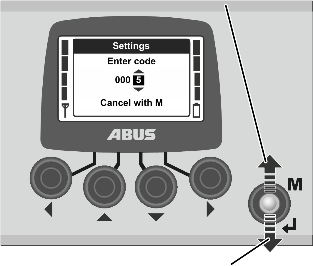
Set the digits using the
UP and DOWN arrow buttons.
Set the code or PIN in
this way.
─ The code for the “Settings” menu is “0005”.
─ The code for the service menu is “0055”.
─ The transmitter PIN code (locking of the transmitter) can be activated and defined as required at any time. See Setting PIN for transmitter PIN code and protected functions.
The factory default setting is “0000”.
─ Only for protected functions: The PIN for protected functions (load limiting system and override of travel limit switches) can be set as required.
The factory default PIN for the protected function “Override travel limit switch” (PIN level 1) is “9001”.
The factory default PIN for the protected load limiting system (PIN level 2) is “8201”.
The factory default PIN for a complete unblocking of all protected functions (PIN level 3) is “0190”.
|
|
Cancel using MENU |
|
| |
|
|
Confirm using ENTER |
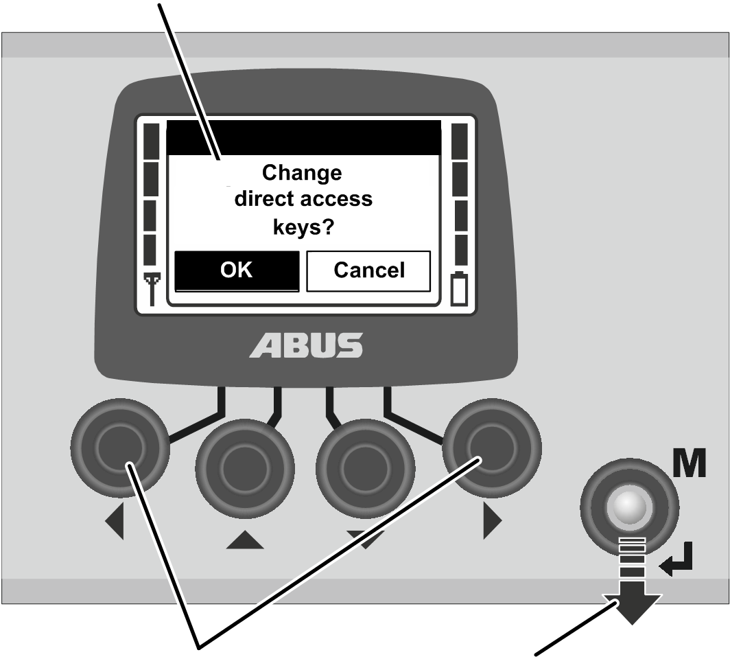
Press
ENTER to confirm or MENU to cancel.
|
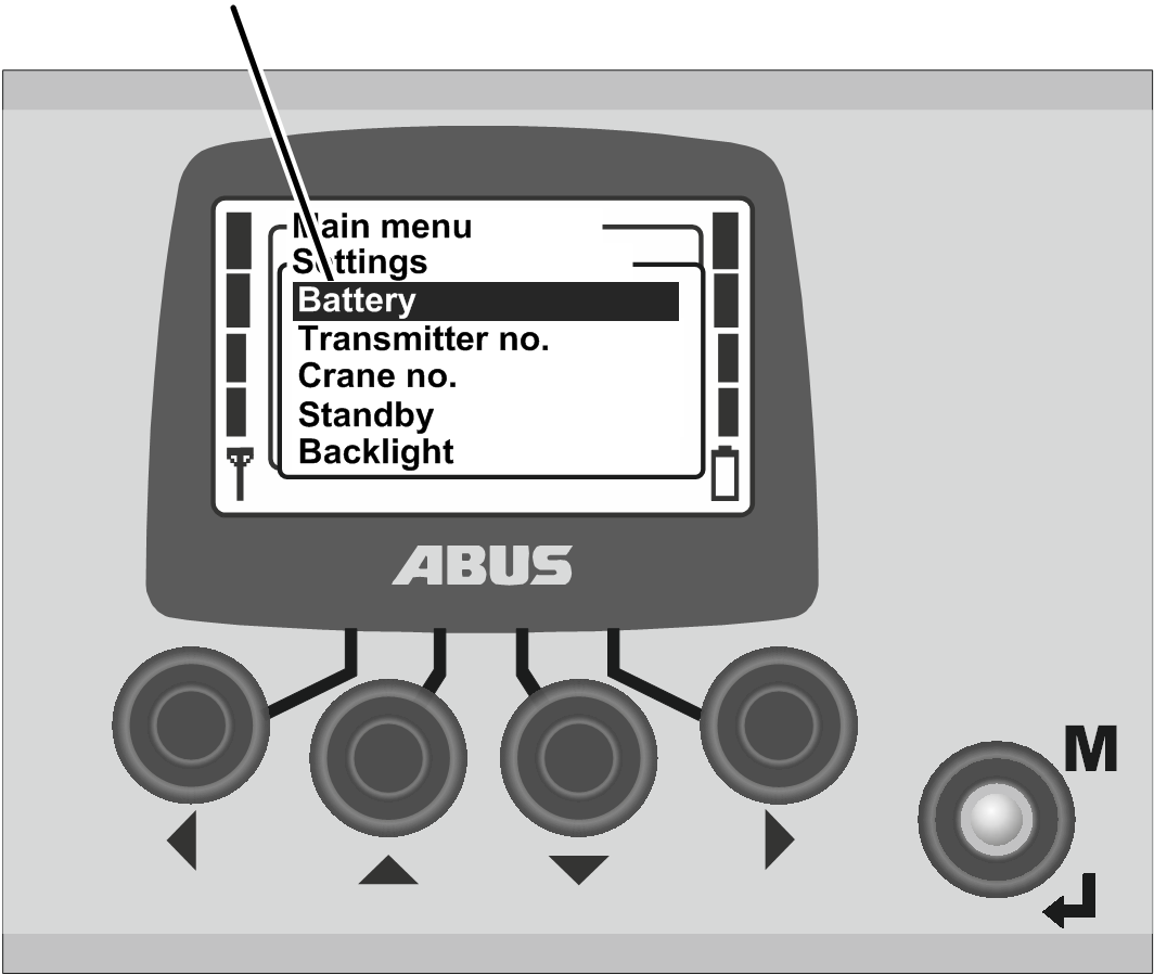
“Settings” menu |
|
|
| |
● The menu item selected appears in the display.
To cancel:
● The transmitter closes the menu and returns to “Normal” operating mode.
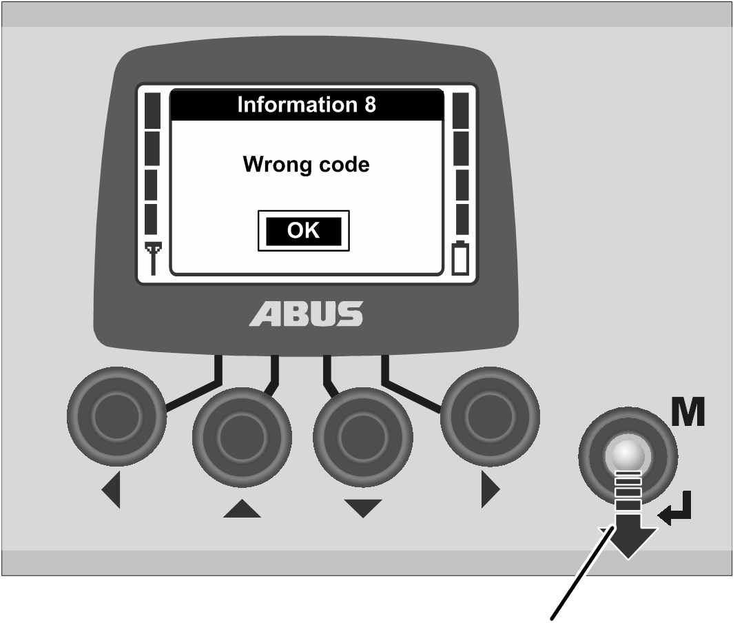
If an incorrect code or PIN was entered:
|
| |
|
|
ENTER |
● The message “Wrong code” or “Wrong PIN” appears on the display.
Press ENTER.
● The code query or PIN prompt appears again on the display.
The code or PIN can be entered incorrectly any number of times. The transmitter will not be disabled if the code or the PIN was entered incorrectly too many times.
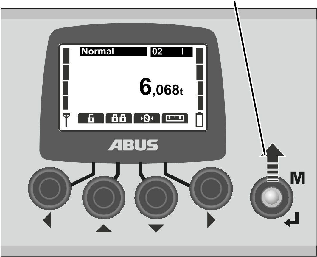
In the “normal” operating mode:
|
|
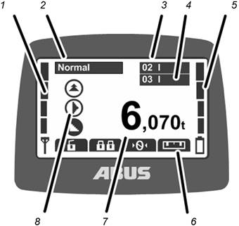
─ 2: Normal operating mode: The current operating mode, “Normal”, appears on the display.
─ 3: “Crane number” and trolley: The display shows the crane number (01, 02, etc.) on which the transmitter is logged in.
For a crane with one trolley, a “I” for trolley I is shown.
For a crane with two trolleys, the selected trolley (I and/or II) is additionally shown. See Operating a crane with two trolleys.
─ 4: “Crane number” and trolley in tandem operation: The display also shows the crane number of the partner crane on which the transmitter is logged in for tandem operation. See Operating cranes in tandem operation.
─ 5: Charge state gauge: The remaining capacity of the rechargeable batteries is shown on the display. Four full bars indicate a full battery; four empty bars indicate an empty battery.
─ 6: Functions set for the direct access buttons: The symbols for the functions assigned to the direct access buttons (arrow buttons) appear on the display. See Setting the direct access buttons.
Symbol with black backlighting: The function is available and can be selected.
Symbol with white backlighting: The function is currently unavailable.
Symbol completely white: No function has been selected for this direct access button.
─ 7: Load display: The current weight of the load suspended in the load hook appears in the display (optional).
─ 8: Symbols for crane travel, trolley travel, lifting/lowering: The corresponding symbol for the joystick appears on the display. See Operating the crane.
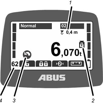
Additional symbols:
|
|
─ 1: Sway control: The display shows whether the sway control is switched on and what length is set for the load lifting attachment. See Switching sway control on and off.
─ 2: Protected load limiting system: The display shows whether the protected load limiting system is switched on (weight symbol with closed padlock) or switched off (weight symbol with opened padlock). See Switching load limiting system on and off.
─ 3: Symbols for slewing: For a jib crane, the symbol display can be toggled to show the symbols for slewing instead of for crane travel. See Setting the crane type for display symbols.
─ 4: Radio channel: The display shows the current radio channel. See Setting the channel display.
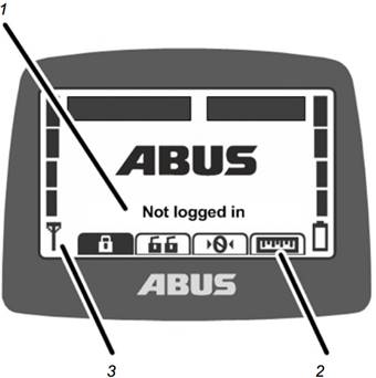
In operating mode “Not logged in”:
|
|
─ 1: Operating mode: The current operating mode “Not logged in” appears on the display.
─ 2: Direct access buttons: All direct access buttons (except “Log in”) are backlit in white (unavailable) on the display.
─ 3: Signal quality: No bar appears on the display because the transmitter is not logged in to a crane.
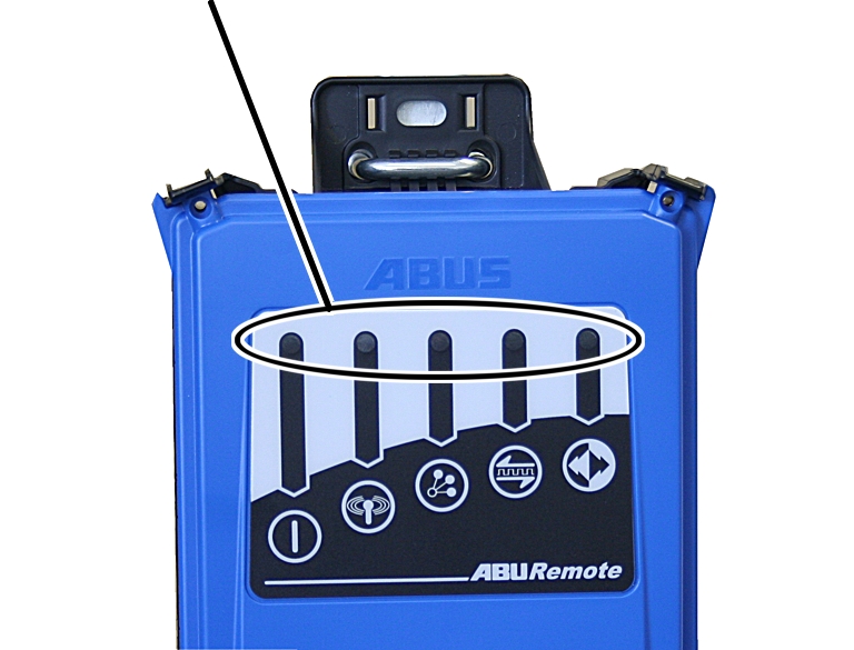
Receiver with relay:
|
LEDs |
|
|
| |
|
Symbol |
Meaning |
|
|
Off: Receiver switched off Flashing: Problem with the operating voltage On: Receiver switched on |
|
|
Off: No wireless connection to transmitter Flashing: Receiver is searching for transmitter On: Wireless connection established |
|
|
Flashes once: Tandem operation deactivated Flashes twice: Tandem operation activated |
|
|
Off: Data connection disconnected Flashing: Data connection quality is poor On: Data connection established |
|
|
Off: Emergency stop pressed Flashing: Transmitter in “Normal” operating mode On: Crane travel, trolley travel, lifting/lowering button pressed |
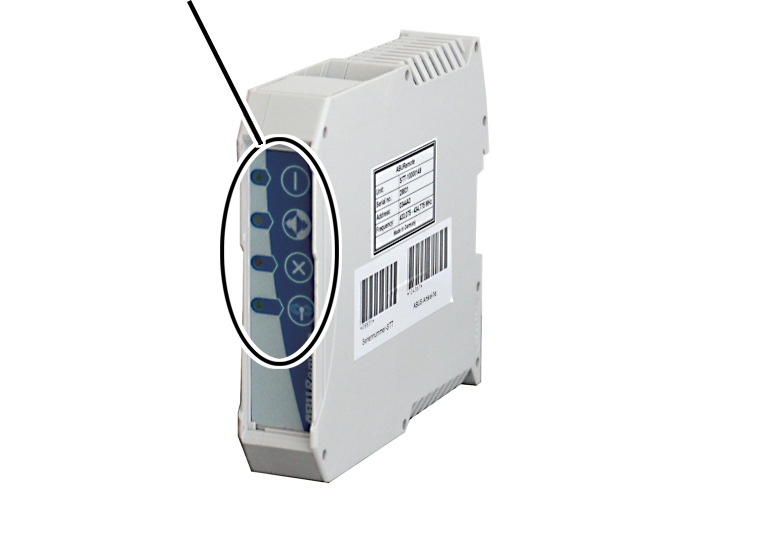
CAN bus receiver:
|
LEDs |
|
|
| |
|
Symbol |
Meaning |
|
|
Off: Receiver switched off Flashing: Problem with the operating voltage On: Receiver switched on |
|
|
Off: Emergency stop pressed Flashing: Transmitter in “Normal” operating mode On: Crane travel, trolley travel, lifting/lowering button pressed |
|
|
Off: Receiver operating fault-free Flashing: Error in the emergency stop function On: Error in the CAN bus network |
|
|
Off: No wireless connection to transmitter Flashing: Receiver is searching for transmitter On: Wireless connection established |