
AT A GLANCE:
General information
This section applies to anyone who lifts loads using the crane, performs work on the crane, or works nearby.
Read before starting work
Using this product manual
The following symbols are used in this product manual:
- This is an instruction regarding an action and prompts you to perform a work step.
- This is the result of an action and describes what happens on the device.
- This is a list.
Only with...
A section that appears in a box framed by a dashed line is only applicable for certain types, versions or options. The condition to which the section applies is specified at the beginning in the heading “Only with...”.
Instructions for the product manual
Read the product manual through carefully before starting work. Also be sure to observe additional product manuals for accessories and components.
Afterwards, keep the product manual available in the vicinity of the crane. It must be accessible to all who work with or on the crane.
If the crane is sold on or hired out, always provide the product manual together with the crane.
Proper use
The radio remote control ABURemote is used for wireless operation of ABUS cranes.
- ABURemote cannot be used on cranes from other manufacturers.
- Do not use ABURemote to operate other devices or machines.
Regulations
The installation has been built and tested according to European standards, rules and regulations applicable at the time of its manufacture. The conventions applied during design and construction are specified in the Declaration of Conformity or the Declaration of Incorporation. The conventions must also be observed for installation, operation, inspection and maintenance, as must the applicable occupational health and safety regulations.
Which provision applies in individual cases will greatly depend on the crane’s use and the national regulations. Review and observe all applicable and current regulations, including the occupational health and safety regulations. Refer also to the Declaration of Conformity or Declaration of Incorporation.
Warranty
- ABUS assumes no liability for damages that were caused by improper use, inadequately trained personnel, incorrect performance of work, nor for any changes, reconstruction or other modification of the crane or crane components which were not approved by ABUS.
- Any warranty claim becomes invalid if components were modified without consent, the crane or crane components were installed, used or serviced in any way other than that described in this product manual, or if parts other than original ABUS replacement parts were used.
- Safe operation of the crane or crane components is only guaranteed if original ABUS replacement parts are used.
Instructions regarding safety
Observe these instructions for safe handling of the crane. Special hazard notices are located in the corresponding sections in which the danger arises.
- If the transmitter is damaged, it could send the wrong commands to the crane. The crane could then lift or travel unchecked. This could result in the death or injury of persons. Only use the transmitter if there are no visible signs of damage on it. Do not throw, drop or jolt the transmitter.
- If the crane operator stumbles or falls, the transmitter may be unintentionally activated. These unintended crane movements could result in the death or injury of persons. Only operate the crane from a safe position with secure footing.
- If the crane operator does not have an unobstructed view of the load, persons could be hit by the load and be killed or injured. Only operate the crane when the load, crane and operating range can all be seen. Otherwise, work together with a banksman.
- When changing location with the transmitter (particularly when turning around), the sensitivity for the travel direction of the crane and trolley changes. This could cause unintended operating commands to be sent in the wrong direction. These unintended crane movements could result in the death or injury of persons. When changing location, proceed with utmost caution. Observe the operating direction signs on the crane and the transmitter!
- If an activated and logged-in transmitter is set aside, unauthorised persons could use the transmitter to operate the crane. These crane movements could result in the death or injury of persons. Never leave an activated transmitter unattended.
- Store the transmitter in a safe place so unauthorised personnel cannot access it.
- Rechargeable batteries can explode or burst if they are thrown on a fire, short-circuited or inserted the wrong way round in the transmitter. Insert rechargeable batteries properly and store in a safe environment.
The Radio Remote Control
Description of the device
The radio remote control is comprised of:
- Transmitter of ABURemote Joystick
- Receiver
- Battery charger
Transmitter of ABURemote Joystick:
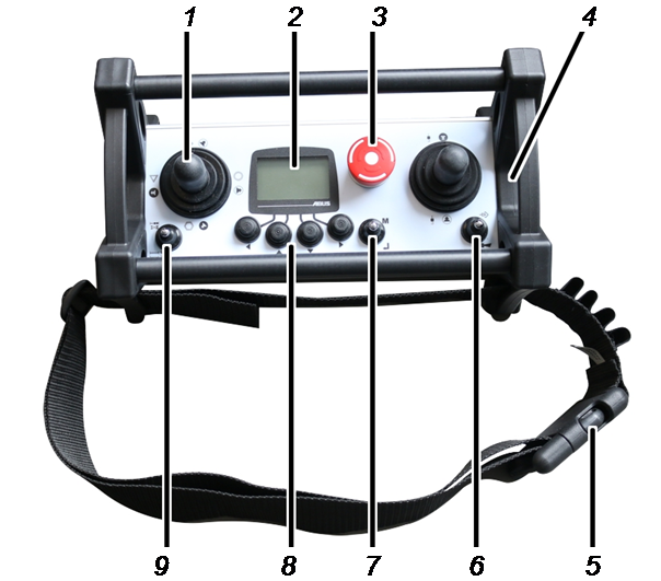
- 1: Joystick for crane travel, trolley travel, lifting/lowering
- 2: Display
- 3: Stop button
- 4: Battery compartment
- 5: HORN and CHANNEL CHANGE flip switch
- 6: Hip belt
- 7: MENU and ENTER flip switch
- 8: Arrow buttons / Direct access buttons
- 9: “Select trolley” and “Select crane” flip switches
Receiver with relay:
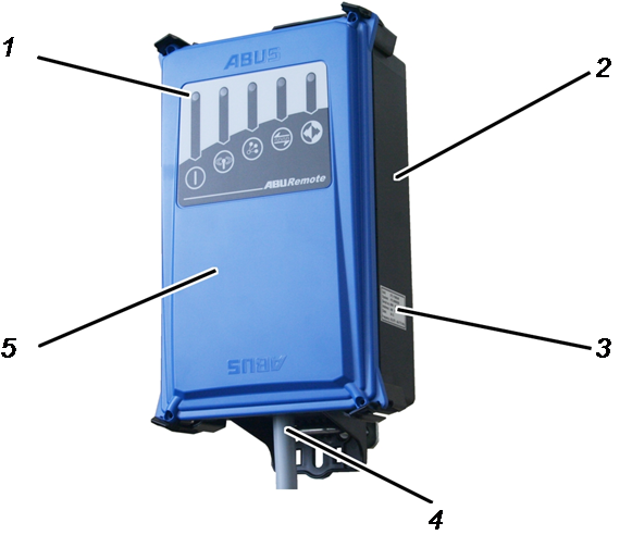
- 1: Status LEDs
- 2: Housing
- 3: Type plate
- 4: Connection cable
- 5: Cover
CAN bus receiver:
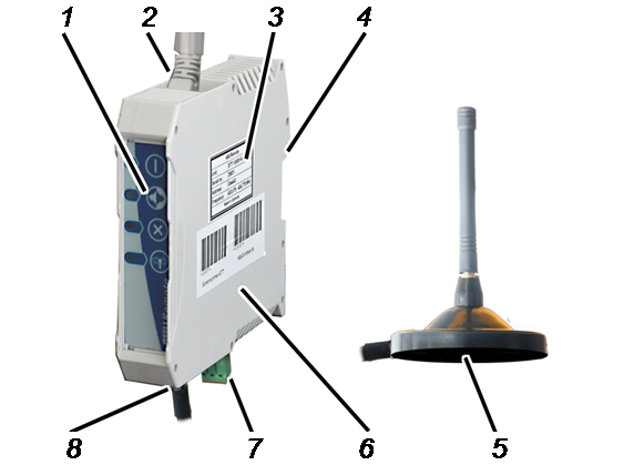
- 1: Status LEDs
- 2: Connection cable for CAN bus network (from above)
- 3: Type plate
- 4: Fastening for top-hat rail
- 5: Magnetic base antenna
- 6: Housing
- 7: Mains connection (from below)
- 8: Connection for magnetic base antenna
Battery charger:
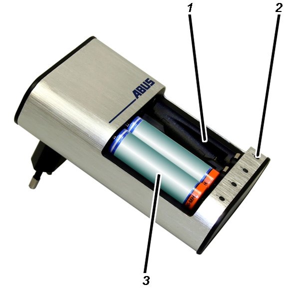
- 1: Charging slots
- 2: Charge state gauge
- 3: Battery
Performance features
The ABURemote radio remote control:
- The ABURemote enables ABUS cranes to be operated remotely.
- ABURemote can be used to operate all the normal crane functions (crane travel/slewing, trolley travel, lifting/lowering) and, depending on the crane equipment, many additional functions.
- ABURemote is tailored especially for the components of ABUS cranes and operates together with the electronic modules of the crane directly (e.g. load indicator system LIS, ABUControl).
- ABURemote has a range of more than 100 metres, depending, for example, on the walls and objects between the transmitter and receiver. Additional factors which can limit the range include other devices with wireless technology, and ambient conditions such as weather and humidity.
- The transmitter features an ergonomic design, making it easy to operate. It can be carried comfortably using the hip belt. The transmitter is lightweight and has large operating elements. It can also be used reliably while wearing gloves.
- The transmitter has an aluminium housing which makes it stable and robust.
- The transmitter houses an internal antenna which cannot break off if the transmitter is dropped.
- The transmitter features a display with coloured lighting which shows the current operating mode. The functions of the radio remote control are adapted to individual needs in the integrated menu.
The current operating mode of the transmitter is also visualised through the background lighting in various colours.
The background lighting uses a light sensor to switch automatically according to the brightness of the surroundings.
- For cranes with the load indicator system LIS-SV or ABUControl crane control: The load attached to the crane is shown on the display during operation. The tare function can be operated using the transmitter.
- The transmitter is operated using two rechargeable AA batteries or two single-use AA batteries.
- ABURemote features semi-automatic frequency management. When switching on, or when the crane operator presses the CHANNEL CHANGE flip switch, ABURemote will search for a free radio channel for data transmission.
The transmitter scans the 433 MHz frequency range or the 868 MHz frequency range and evaluates the current radio situation in its surroundings. Based on this, the transmitter selects the most optimal radio channel for the connection.
- At least 20 ABURemote units can be operated in parallel without causing interference. The actual number may be limited by other devices which use wireless transmission.
- ABURemote is designed so that the crane is deactivated in the event of a faulty signal or radio interference, preventing it from operating unchecked.
- ABURemote has a reliable emergency stop function. The transmitter continuously emits a ready signal to the receiver. If this ready signal is not detected for half a second (e.g. due to radio interference), the receiver switches to emergency stop. In addition, the transmitter emits an active stop signal when the stop button is pressed.
- The transmitter features a “Standby” operating mode. The transmitter switches to “Standby” operating mode when no button is pressed within a preset time.
- ABURemote normally operates in the 433 MHz ISM frequency range or in the 868 MHz ISM frequency range (variant).
The data transmission is based on a 4 GFSK modulation. This enables a short signal propagation delay, in other words, a fast response from the crane.
- The receiver is available for delivery as receiver with relay or as CAN bus receiver.
- The receiver with relay has an inner-lying antenna and a compact construction, status indicator LEDs which are visible from a distance and can also be opened quickly with conventional tools.
- The CAN bus receiver is intended for top-hat rail assembly in the crane control. It has a connection for an external magnetic base antenna and is designed for use with the ABUControl crane control unit.
With tandem control system:
- ABURemote can be used to control two cranes with a tandem control system. The transmitter is logged in on both cranes and controls them in a synchronised manner. The monitoring of limit switches and other safety functions is ensured by the control of the two overhead travelling cranes.
- It is possible to switch back and forth between the two cranes using the transmitter. Switching on the tandem control system temporarily enables control of an individual crane (e.g. for slinging the load or compensating height differences).
With two trolleys on one crane:
- For trolley selection I I+II II: It is possible to switch back and forth between the two trolleys using the transmitter. This allows the trolleys to be operated alternately. Furthermore, joint operation can be selected which allows the trolleys to be operated together.
- For trolley selection I II: It is possible to switch back and forth between the two trolleys using the transmitter. This allows the trolleys to be operated alternately.
- For individual control: The transmitter allows both trolleys to be operated independently of one another, each being operated with a joystick of its own.
- For individual control, changeover to joint operation is possible: The transmitter allows both trolleys to be operated independently of one another, each with a joystick of its own. Furthermore, joint operation can be selected, allowing both trolleys to be operated together using one joystick.
For hook assistants (hook guidance and hook centring):
- The hook guidance allows the load hook to be moved by hand.
Both the crane and the trolley travel in the direction the load hook is moved or pulled. - The “Hook centring” function automatically positions the load hook vertically above the load when the load is attached. This facilitates and speeds up positioning of the trolley vertically and, if necessary, reduces diagonal pull.
- The direct access button “Travel release” switches the hook guidance/hook centring on and off. See “Using the ” or “Using the ”.
- The hook assistants work by precisely measuring the wire rope deflection. An inclinometer which measures the wire rope deflection is attached to the fixed point crosshead, the drum housing or the trolley frame. The inclinometer position can be adjusted in KranOS. See the “ABUControl” product manual.
- To be able to use the function, perform a calibration run before startup
multiple times with the load hook unladen from the lower to upper hook
position.
This determines the zero position of the inclinometer. The inclinometer calibration is activated in KranOS. See the “ABUControl” product manual. - The hook assistants only work with a single hoist or on a crane with several trolleys provided the unused trolley is not selected and in the parking position (load hook triggers top hoist limiter).
- If the hook guidance/hook centring is active, position control cannot be activated. The functions can therefore not be used simultaneously.
Positioning control:
- Using the positioning control, you can move to pre-determined positioning points (manual or linear) or a follow route with up to 8 route points.
Positioning points (manual or linear) can be created or modified in KranOS. Route points cannot be created or changed in KranOS.
See the “ABUControl” product manual.
- The positioning control is switched on and off using the direct access
button or the menu. Target positions can be selected and saved in the
menu. For saving the positions, see: “Positioning
control on ABUControl: Teaching in positioning points”
or “Positioning
control on ABUControl: Teaching in routes”
For applying the function, see: “Positioning control on ABUControl: Teaching in positioning points and route point”.
The battery charger:
- The battery charger can charge 1 to 4 rechargeable batteries (NiMH).
- The battery charger monitors each individual charging slot separately from the other.
- The battery charger monitors the battery temperature, prevents overcharging, detects defective batteries and detects any single-use battery inserted.
- The battery charger detects when the rechargeable battery is charged and switches over to trickle charging.
- With the separate battery charger and two sets of batteries, the transmitter can be used without interruption (e.g. in three-shift operation).
Technical data
Transmitter:
Electrical connection |
|
|---|---|
Operating voltage |
2.0 V to 5.0 V DC |
Current consumption |
50 mA to 130 mA |
Transmission power |
< 10 dBm |
Weight (without batteries and hip belt) |
1.7 kg |
Ambient conditions for operation |
|
|---|---|
Protection class |
IP 65 |
Relative humidity |
20 % to 90 % non-condensing |
Ambient temperature |
-20 °C to +70 °C |
Receiver with relay:
Electrical connection |
|
|---|---|
Operating voltage |
42 V to 270 V AC |
Mains frequency |
50 Hz/60 Hz |
Current consumption |
~100 mA |
Voltage at the outputs |
Equivalent to the operating voltage |
Weight |
1.1 kg |
Ambient conditions for operation |
|
|---|---|
Protection class |
IP 65 |
Relative humidity |
20 % to 90 % non-condensing |
Ambient temperature |
-20 °C to +70 °C |
CAN bus receiver:
Electrical connection |
|
|---|---|
Operating voltage |
24 V DC |
Current consumption |
< 100 mA |
Max. transmission power |
≤ 10 mW |
Ambient temperature |
-20 °C to +80 °C |
Battery charger:
Electrical connection |
|
|---|---|
Operating voltage |
100 V to 240 V |
Mains frequency |
50 Hz to 60 Hz |
Current consumption |
Max. 145 mA |
Disposing of ABURemote
If ABURemote is to be disposed of:
- Dismantle transmitter and receiver as far as possible.
- Observe local regulations concerning disposal and recycling.
- Dispose of the individual parts sorted by material in an environmentally sound manner.
- Dispose of electronic components as scrap electronic parts.
- Dispose of cables and plug-in connections as scrap electronic parts.
- The housing and plastic parts should be recycled with plastic waste.
- Dispose of metal parts as scrap metal.

Disposing of rechargeable batteries
- Do not dispose of rechargeable batteries with the household waste. Dispose of them in accordance with the locally applicable regulations.
Using the ABURemote menu
Functions of the buttons
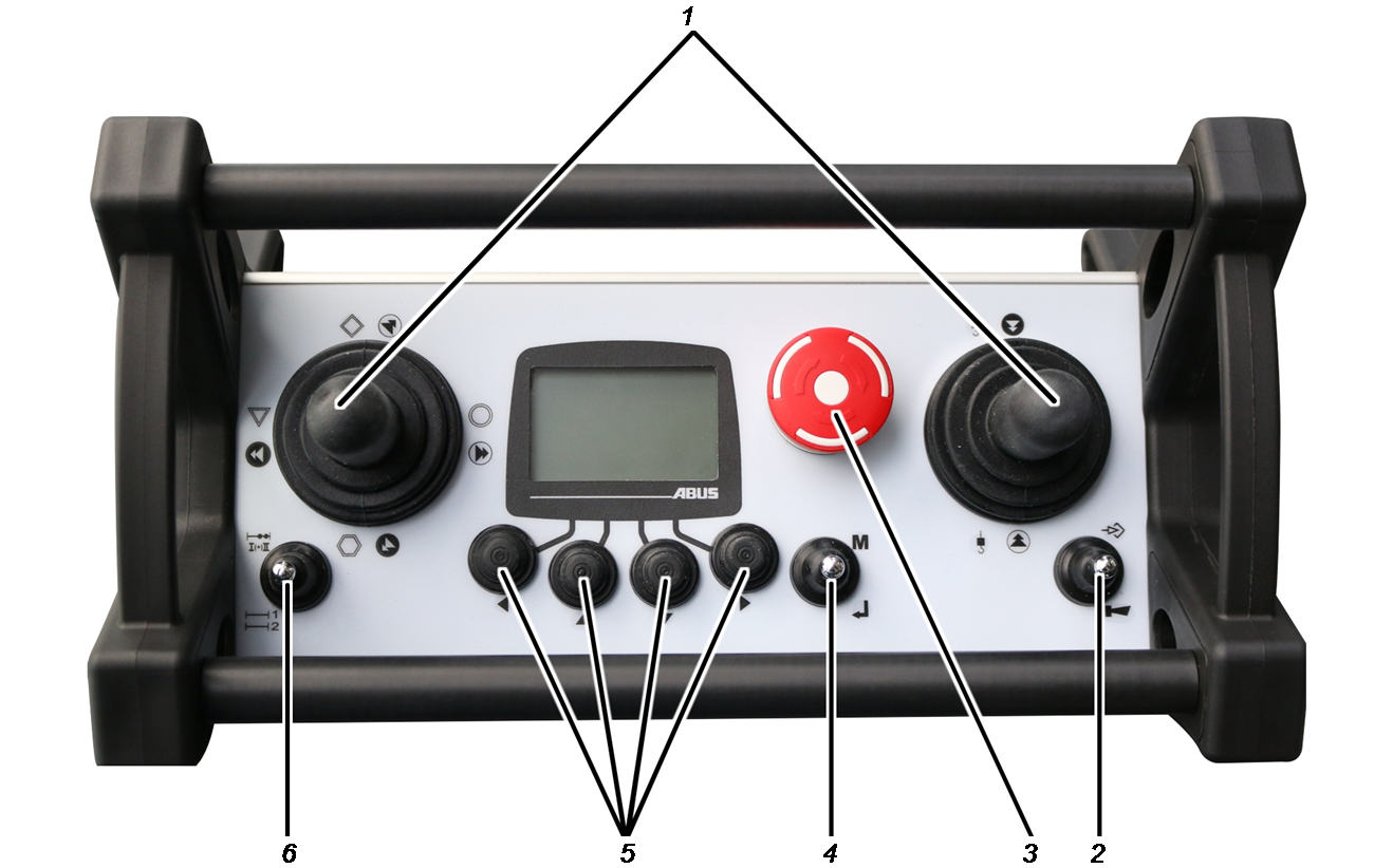
- 1: Joystick:
Operating the crane. See “Lifting and lowering, trolley travel, crane travel”.
- 2: HORN and CHANNEL CHANGE flip switch:
Press towards HORN: activate the horn. See “Horns”.
Press towards CHANNEL CHANGE: Searches for a different, free radio channel and switches to it. See “Changing the radio channel”.
- 3. Stop button:
Triggers an emergency stop on the crane. See “Emergency stop”.
Switches transmitter on and off. See “Checking, switching on and releasing prior to beginning work” and “Logging out and switching off the transmitter”.
- 4: MENU and ENTER flip switch:
Press towards MENU: Opens the main menu or closes it. See “Opening and closing the menu and menu items”.
Press towards ENTER: Opens menu items and confirms values. See “Using the ABURemote menu”.
- 5: Arrow buttons / Direct access buttons:
In the menu: Menu operation. See “Using the ABURemote menu”.
In “Normal” operating mode: Can be assigned as direct access buttons with additional crane functions (e.g. tare, crane lighting). See “Setting the direct access buttons”.
- 6: “Select trolley” and “Select crane” flip switches
Press towards “Select crane”: Selects one of the two cranes or both cranes. See “Operating cranes in tandem operation”.
Press towards “Select trolley”: Selects one of the two trolleys or both trolleys. See “Operating a crane with two trolleys”.
Opening and closing the menu and menu items
Many functions and settings can be conveniently selected from the menu.
To open the menu and menu items:
Main menuMENU
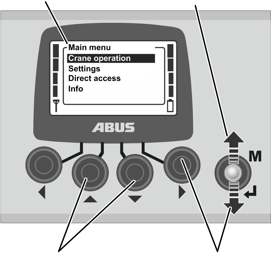
- Press MENU.
- The main menu is shown in the display.
- Select the desired menu item using the UP and DOWN arrow buttons.
- The menu item selected is backlit in black.
- Open the selected menu item using the RIGHT arrow button or ENTER.
Submenu
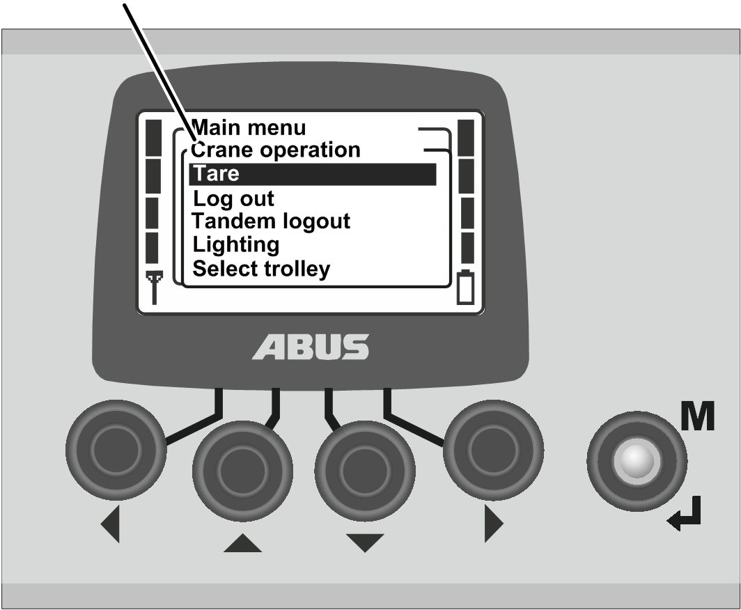
- The opened menu item or a submenu appears in the display.
To switch to the previous menu or return to the main menu:
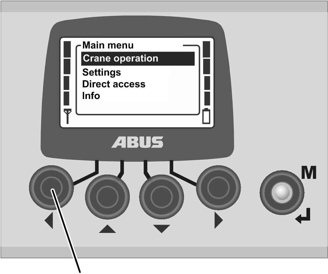
- Press the LEFT arrow button.
- The previous menu or main menu appears on the display again.
To quit the menu:
MENU
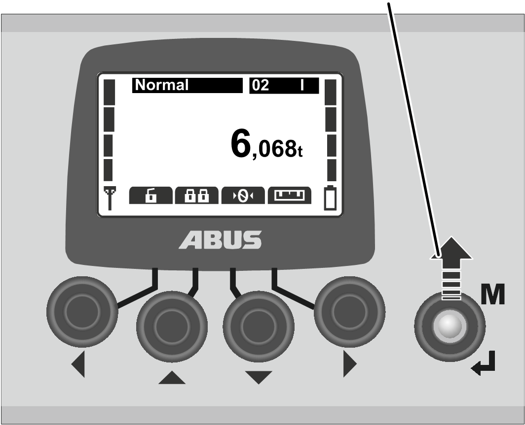
- Either:
Press MENU.
Or:
Press the LEFT arrow button several times.
- The transmitter closes the menu and returns to the previous operating mode.
Changing a value
Values can be selected or set for many functions.
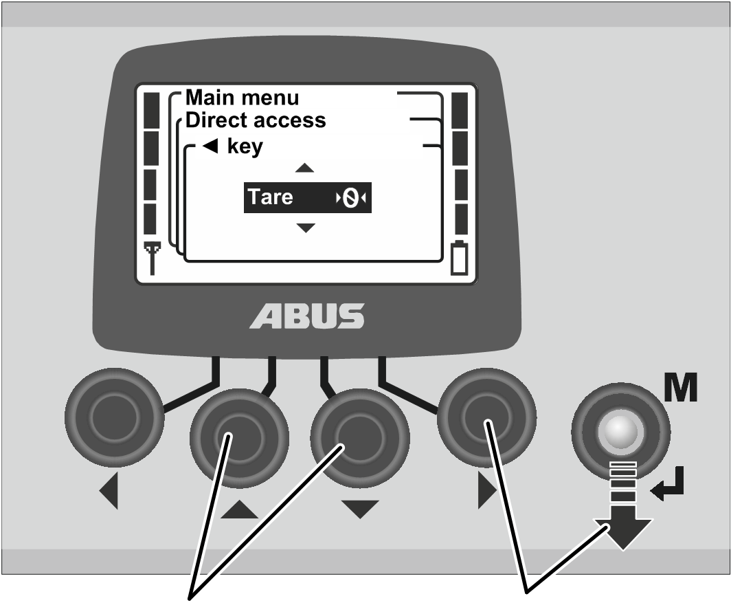
- A window with the currently set or selected value appears on the display.
- If values can be selected or set at several places on the display: Select a place using the RIGHT and LEFT arrow buttons.
The place selected is backlit in black.
- Select or set the required value using the UP and DOWN arrow buttons.
- Confirm the selected or set value using the RIGHT arrow button or using ENTER.
- The value selected or set is now saved.
If the value does not need to be changed:
- Either:
Use MENU to quit the menu.
Or:
Use the LEFT arrow button to change back to the previous menu.
Confirming or cancelling a message
Error codes or other information appear in the form of messages.
Message
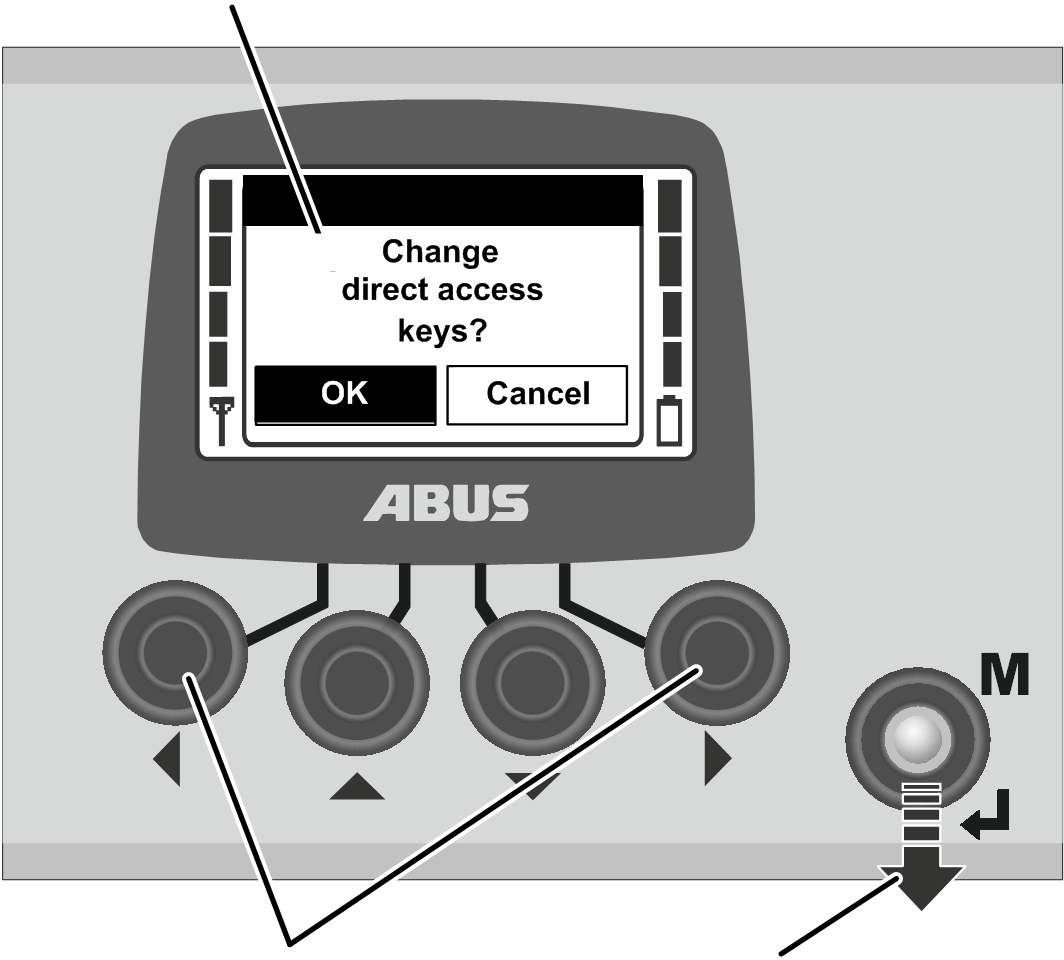
- Only with multiple buttons: Select the required button (backlit in black) using the LEFT and RIGHT arrow buttons.
- Press ENTER.
Entering the code or PIN
A number of menus are protected by a code to prevent any unintentional changes. Furthermore, the entire transmitter as well as certain functions can be protected by a PIN.
UP and DOWNCode 0005
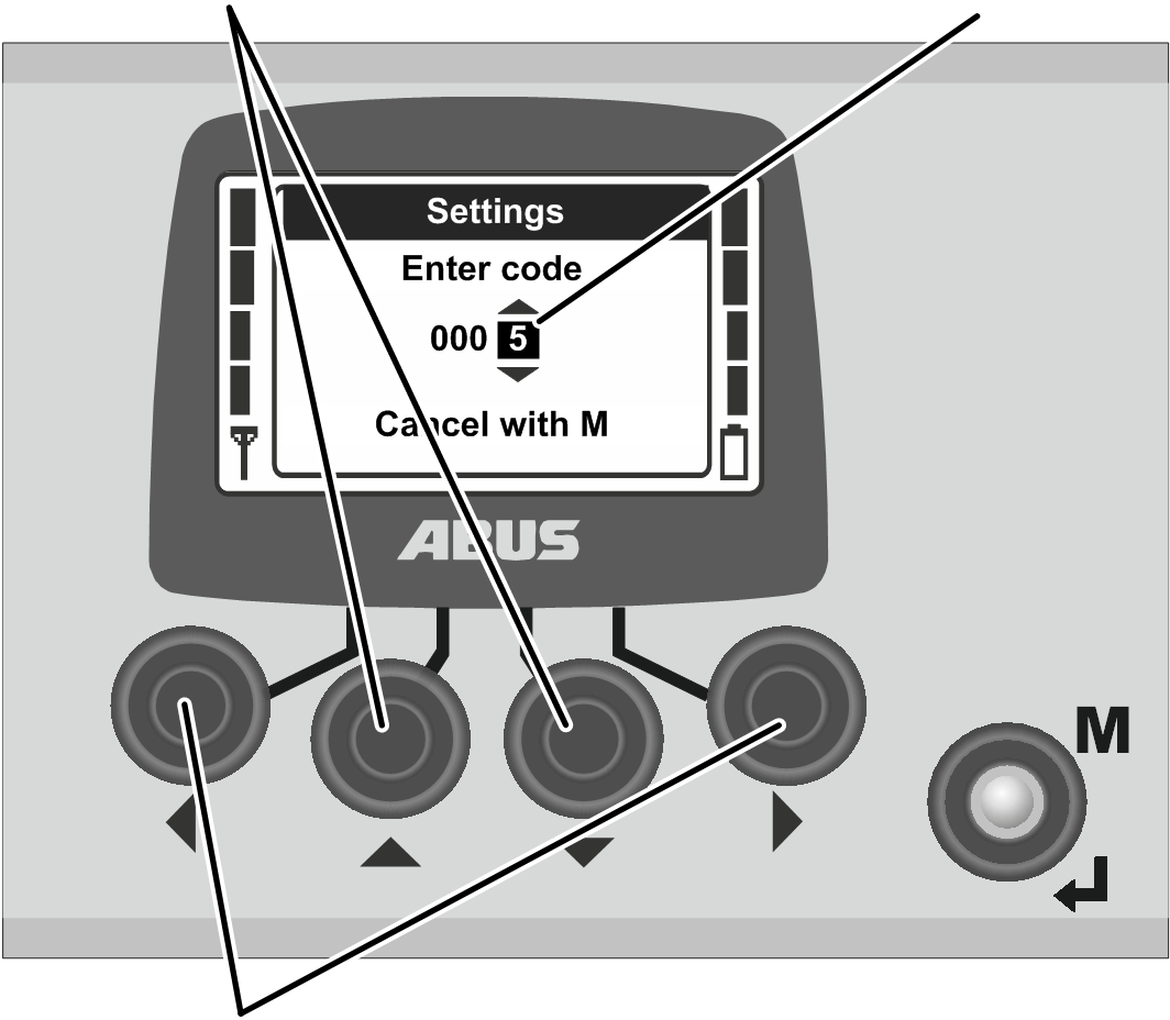
- The display shows the code query (protection of certain menus) or the PIN prompt (transmitter PIN code and protected functions).
- Select the digits to be set using the LEFT and RIGHT arrow buttons.
- The digit selected is backlit in black.
- Set the digits using the UP and DOWN arrow buttons.
- Set the code or PIN in this way.
- The code for the “Settings” menu is “0005”.
- The code for the service menu is “0055”.
- The transmitter PIN code (locking of the transmitter) can be activated and defined as required at any time. See “Setting PIN for transmitter PIN code and protected functions”.
The factory default setting is “0000”.
- Only for protected functions: The PIN for protected functions (load limiting system and override limit switches) can be set as required.
The factory default PIN for the protected function “Override limit switch” (PIN level 1) is “9001”.
The factory default PIN for the protected load limiting system (PIN level 2) is “8201”.
The factory default PIN for a complete unblocking of all protected functions (PIN level 3) is “0190”.
Cancel using MENU
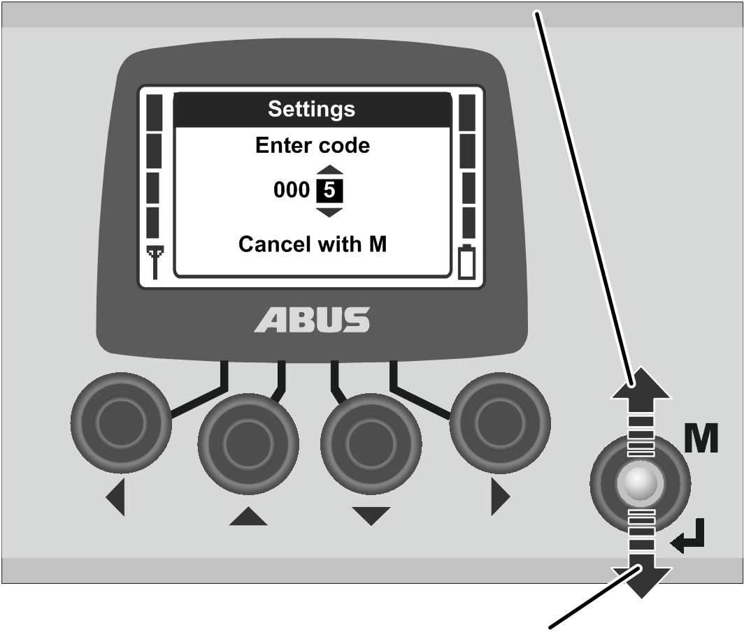
- Press ENTER to confirm or MENU to cancel.
To confirm:
“Settings” menu
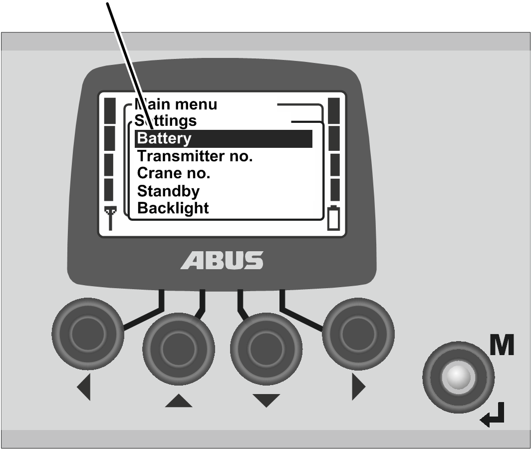
- The menu item selected appears in the display.
To cancel:
- The transmitter closes the menu and returns to “Normal” operating mode.
If an incorrect code or PIN was entered:
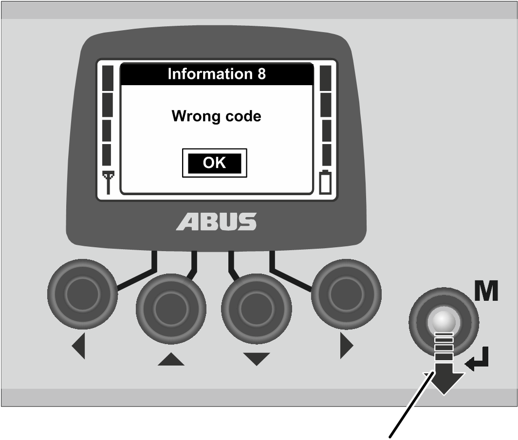
- The message “Wrong code” or “Wrong PIN” appears on the display.
- Press ENTER.
- The code query or PIN prompt appears again on the display.
The code or PIN can be entered incorrectly any number of times. The transmitter will not be disabled if the code or the PIN was entered incorrectly too many times.
Display in normal operating mode (transmitter)
In the “normal” operating mode:
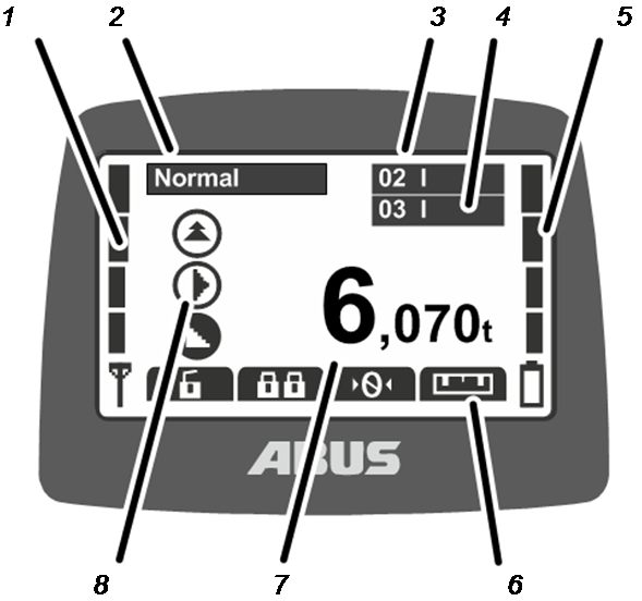
- 1: Signal: The signal quality of the wireless connection appears on the display. The fewer bars shown, the poorer the signal quality.
- 2: Normal operating mode: The current operating mode, “Normal”, appears on the display.
- 3: “Crane number” and trolley: The display shows the crane number (01, 02, etc.) on which the transmitter is logged in.
For a crane with one trolley, a “I” for trolley I is shown.
For a crane with two trolleys, the selected trolley (I and/or II) is also shown. See “Operating a crane with two trolleys”.
For a crane with one trolley, you can also switch between the displays for “I” or “II” on the transmitter, but only trolley I will be controlled.
- 4: “Crane number” and trolley in tandem operation: The display also shows the crane number of the partner crane on which the transmitter is logged in for tandem operation. See “Operating cranes in tandem operation”.
- 5: Charge state gauge: The remaining capacity of the rechargeable batteries is shown on the display. Four full bars represents a fully charged battery; four empty bars indicates the battery is empty.
- 6: Functions set for the direct access buttons: The symbols for the functions assigned to the direct access buttons (arrow buttons) appear on the display. See “Setting the direct access buttons”.
Symbol with black backlighting: The function is available and can be selected.
Symbol with white backlighting: The function is currently unavailable.
Symbol completely white: No function has been selected for this direct access button.
- 7: Load display: The current weight of the load suspended in the load hook appears in the display (optional).
- 8: Symbols for crane travel, trolley travel, lifting/lowering: The corresponding symbol for the joystick appears on the display. See “Operating the crane”.
Additional symbols:
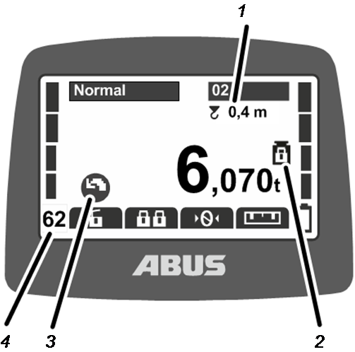
- 1: Sway control: The display shows whether the sway control is switched on and what length is set for the load lifting attachment. See “Using sway control ”.
- 2: Protected load limiting system: The display shows whether the protected load limiting system is switched on (weight symbol with closed padlock) or switched off (weight symbol with opened padlock). See “Switching load limiting system on and off”; “Switching load limiting system on and off”.
- 3: Symbols for slewing: For a jib crane, the symbol display can be toggled to show the symbols for slewing instead of for crane travel. See “Setting the crane type for display symbols”.
- 4: Radio channel: The display shows the current radio channel. See “Setting the channel display”.
In operating mode “Not logged in”:
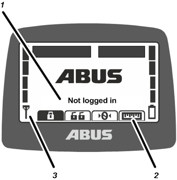
- 1: Operating mode: The current operating mode “Not logged in” appears on the display.
- 2: Direct access buttons: All direct access buttons (except “Log in”) are backlit in white (unavailable) on the display.
- 3: Signal quality: No bar appears on the display because the transmitter is not logged in to a crane.
Display in normal operating mode (Receiver)
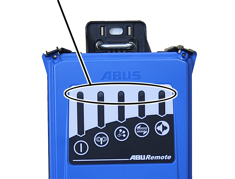
Receiver with relay:
LEDs
Symbol |
Meaning |
|---|---|
|
Off: Receiver switched off Flashing: Problem with the operating voltage On: Receiver switched on |
|
Off: No wireless connection to transmitter Flashing: Receiver is searching for transmitter On: Wireless connection established |
|
Flashes once: Tandem operation deactivated Flashes twice: Tandem operation activated |
|
Off: Data connection disconnected Flashing: Data connection quality is poor On: Data connection established |
|
Off: Emergency stop pressed Flashing: Transmitter in “Normal” operating mode On: Crane travel, trolley travel, lifting/lowering button pressed |





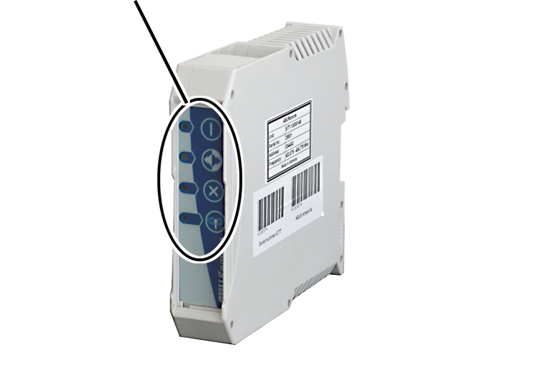
CAN bus receiver:
LEDs
Symbol |
Meaning |
|---|---|
|
Off: Receiver switched off Flashing: Problem with the operating voltage On: Receiver switched on |
|
Off: Emergency stop pressed Flashing: Transmitter in “Normal” operating mode On: Crane travel, trolley travel, lifting/lowering button pressed |
|
Off: Receiver operating fault-free Flashing: Error in the emergency stop function On: Error in the CAN bus network |
|
Off: No wireless connection to transmitter Flashing: Receiver is searching for transmitter On: Wireless connection established |

Overview of main menu
Opening and operating the main menu: See “Opening and closing the menu and menu items”.
Menu item |
Menu item |
Functions |
Direct access button |
See |
|---|---|---|---|---|
“Crane operation” |
“Tare” |
Set load display to zero |
|
“Tare”. |
“Log in” |
Log in the transmitter on the receiver. |
|
“Checking, switching on and releasing prior to beginning work”. |
|
“Log out” |
Log out the transmitter from the receiver. |
|
||
“Tandem login” |
Log in the transmitter on the second crane for tandem operation. |
|
||
“Tandem logout” |
Log out the transmitter from the second crane in tandem operation. |
|
||
“Lighting” |
Switch the crane lighting on and off. |
|
||
“Sway control on” |
Switch on the sway control and set the length of the load lifting attachment. |
|
||
“Sway control off” |
Switch sway control off. |
|
||
“Select trolley” |
Switch between trolley I, trolley II and trolley III |
(not available) |
||
“Select crane” |
Switch between the first and second crane in individual operation and tandem operation. |
(not available) |
||
(not available as menu item) |
Override limit switch for a bypass control. |
|
||
“Sup.pre.lift on” |
Switch on super-precision lifting on the wire rope hoist. |
|
||
“Sup.pre.lift off” |
Switch off super-precision lifting on the wire rope hoist. |
|


Menu item |
Menu item |
Functions |
Direct access button |
See |
|---|---|---|---|---|
“Teach-In” |
Perform teach-in with an electronic hoist limit switch or determine points for positioning control. |
|
“Performing teach-in with an electronic hoist limit switch” or “Teaching in positioning points”, “Positioning control on ABUControl: Teaching in positioning points” or “Teaching in routes”, “Positioning control on ABUControl: Teaching in routes” |
|
“Positioning” |
Approach positions of a positioning control. |
|
“Positioning assistance: Approaching positions” or “Positioning control on ABUControl: Teaching in positioning points and route point”. | |
“Settings” |
“Battery” |
Displaying the remaining battery charging time and set the alarm |
“Displaying the remaining battery time and setting the alarm”. |
|
“Transmitter no.” |
Set the number of the transmitter which will be shown on the display. |
|||
“Crane no.” |
Set the number of the crane which will be shown on the display. |
|||
“Standby” |
Set the time which elapses before the transmitter changes to “Standby”. |
|||
“Light sensor” |
Set the sensitivity of the light sensor for the display light |
|||
“Language” |
Select the language for menus and messages. |
|||
“Crane type” |
Select the crane type (overhead travelling crane or jib crane) for display symbols |
|||
“Direct access” |
“◄ key” |
Select the assignment of the direct access button. |
||
“▼ key” |
Select the assignment of the direct access button. |
|||
“▲ key” |
Select the assignment of the direct access button. |
|||
“► key” |
Select the assignment of the direct access button. |
|||
“Info” |
Display the electronic type plate |



Overview of service menu
Menu item |
Menu item |
Functions |
Access to menu item |
See |
|---|---|---|---|---|
“Radio” |
“Channel” |
Activate automatic search for a free radio channel or set a fixed radio channel. |
With transmitter logged out or logged in |
|
“Channel range” |
Limit the automatic search for a free radio channel to certain radio channels |
Only with transmitter logged out |
||
“Channel display” |
Switch on display of the radio channel in “Normal” operating mode |
With transmitter logged out or logged in |
||
“Address” |
Set the address of the receiver in the transmitter. |
Only with transmitter logged out |
||
“Application” |
Set the application of the transmitter (model and versions) |
Only with transmitter logged out |
||
“Transmit power” |
“Transmitter” |
Set the transmission power of the transmitter |
With transmitter logged out or logged in |
“Setting the transmission power of transmitter and receiver”. |
“Receiver” |
Set the transmission power of the receiver |
Only with transmitter logged in |
“Setting the transmission power of transmitter and receiver”. |
|
“Operating hours” |
“Transmitter” |
Display operating hours counter of the transmitter |
With transmitter logged out or logged in |
|
“Receiver” |
Only with transmitter logged in |
|||
“Selection mode” |
Set the selection mode for “Select trolley” and “Select crane” using the flip switch |
With transmitter logged out or logged in |
“Selection mode for setting the trolley selection and crane selection”. |
|
“Waiting time” |
Set the waiting time after the logging in and the release signal for powering up the crane control |
Only with transmitter logged in |
||
“Set PIN” |
Set PIN for transmitter PIN code and activate and set protected functions |
With transmitter logged out or logged in |
“Setting PIN for transmitter PIN code and protected functions”. |
|
“Deactivate PIN” |
Switch off all PIN levels for transmitter PIN code and protected functions |
With transmitter logged out or logged in |
Installing and connecting
This section applies to anyone who works on the crane prior to its use
The end user of the crane is responsible for the proper qualifications of the commissioning personnel.
Examples of qualified persons:
- Persons with comprehensive knowledge from specialist training in engineering and in the electrical systems of cranes.
- Persons with sufficient experience in the operation, installation and maintenance of cranes.
- Persons with comprehensive knowledge regarding the relevant technical rules, directives and safety regulations applicable in the respective country.
- Persons receiving regular training from ABUS.
ABUS assumes no liability for damage due to incorrectly performed commissioning work done by unqualified personnel.
ABUS recommends having the commissioning work performed by the ABUS assembly team.
Checking the requirements
The following requirements must be met in order to install the radio remote control:
- A warning device (e.g. horn) must be available.
- The crane and trolley must have an emergency end stop device (e.g. a buffer or limit switch with braking function and/or shut-down).
Planning the installation on the crane
- Prior to installation, plan where and how to install the receiver on the crane.
Planning the receiver attachment
For a wireless connection that is as stable as possible:
- The receiver must be positioned so that it can transmit freely in all directions. The receiver may therefore not be blocked by metal parts in its direct vicinity.
- The minimum clearance between the receiver and metal parts in any direction is 1 m.
- Plan the position of the receiver so that it can be connected to the crane panel using the connection cable supplied.
- The receiver must be positioned vertically and the connection cable must be guided downward out of the receiver.
- The receiver must be positioned so that the LEDs point toward the midpoint of the crane and are easy to read in the operating range of the crane.
Only with CAN bus receiver
Example for the installation of the CAN bus receiver:
CAN bus receiver
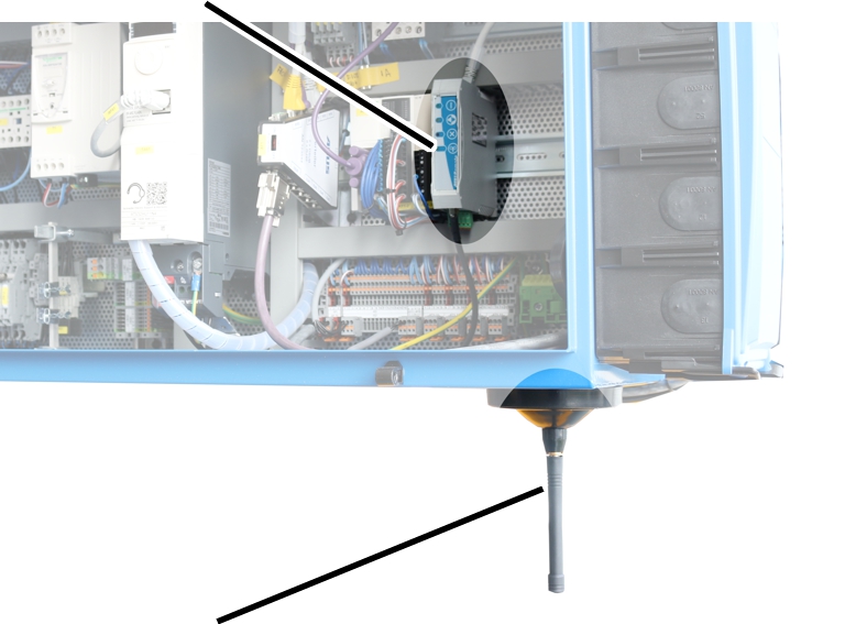
- The CAN bus receiver is installed in the crane panel. To provide a wireless connection that is as stable as possible, an external magnetic base antenna is connected and guided out of the crane panel.
- The instructions stated above apply to the installation of the magnetic base antenna.
- Attach the magnetic base antenna so that nothing becomes caught during crane travel or trolley travel.
Planning the receiver position
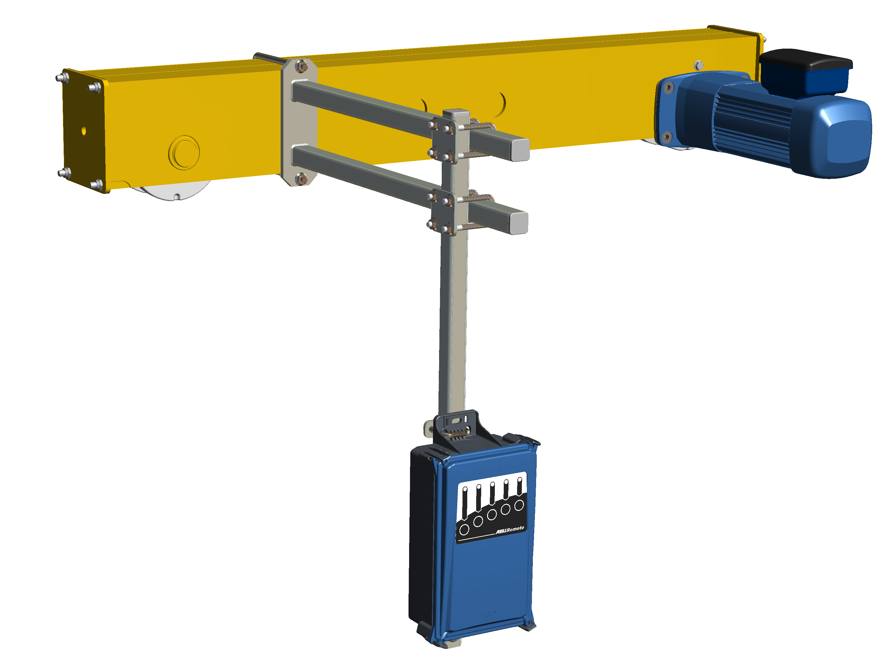
- Single girder travelling crane: The receiver should be fastened on the end carriage as shown in the illustration. The receiver should protrude downward under the main girder in order to be able to transmit freely in all directions.
- Double girder travelling crane: The receiver should be fastened between the two main girders as shown in the illustration. The receiver should protrude downward under the main girders in order to be able to transmit freely in all directions.
- Wall travelling crane: The receiver should be fastened on the middle end carriage as shown in the illustration. The receiver should hang at about the height of the lower end carriage of the wall travelling crane.
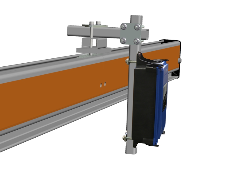
- HB system: The receiver should be fastened as shown in the illustration with a clamping unit in the profile head on the crane girder.
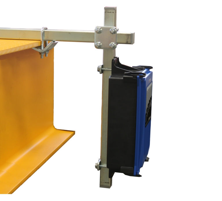
- Underslung travelling crane: The receiver should be fastened as shown in the illustration with clamping claws on the upper flange on the main girder.
- Jib crane: The receiver should be fastened as shown in the illustration with clamping claws on the upper flange on the jib arm.
Installing the receiver on the crane
The illustrations show the installation of the receiver on the end carriage of a single girder travelling crane. The installation on other overhead travelling cranes does not essentially differ.
Mount for installing the receiver
Threaded bracket
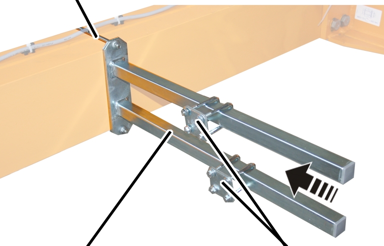
- Attach the mount to the end carriage on which the crane panel is installed.
- Bolt the mount onto the threaded bracket.
Threaded bracket |
Tightening torque |
|---|---|
M8 |
25 Nm |
M10 |
50 Nm |
M12 |
75 Nm |
- Slide on the pipe clamps (2x) and secure them.
Installing the square tube onto the mount
Vertical square tube
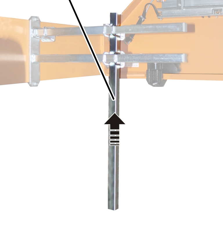
- Move the vertical square tube to the required position on the mount.
The required length is determined by the on-site conditions in the building and the safety clearances from the crane drawing.
- Screw the vertical square tube onto the mount using pipe clamps (2x). 15 Nm.
Installing the receiver on the square tube
Threaded bracketPlate
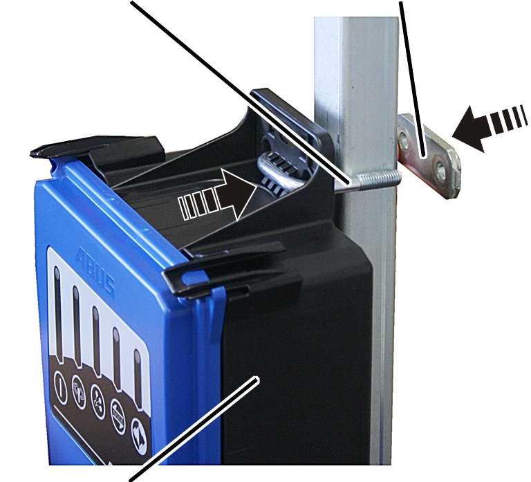
- Hold the receiver on the square tube.
- Insert one threaded bracket each through the top and bottom of the housing.
- Insert one plate onto each threaded bracket from the rear side.
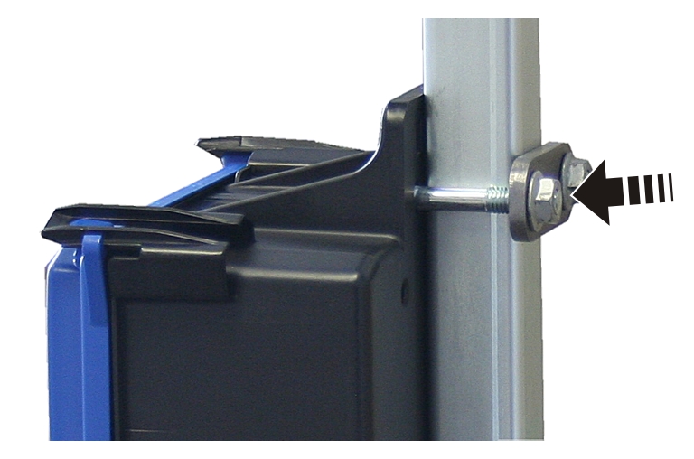
- Tighten the threaded bracket with the rib nuts M8 (2 x per threaded bracket). 15 Nm.
Connecting the receiver on the crane
- Lay the connection cable to the crane panel.
- Fasten the connection cable in place using cable ties.
- Insert the connector in the socket X2 on the crane panel.
- Do not lay the CAN bus line and connection cable of the magnetic base antenna with kinks or bends of a small radius.
Testing after substantial changes
- If the ABURemote is being retrofitted to an existing crane: Observe the local regulations and conduct the “Test after substantial changes”.
Registering the radio remote control
ABURemote does not require registration and is exempt from fees in most countries.
- Check and observe the country-specific regulations.
Overview of screw tightening torques
Receiver
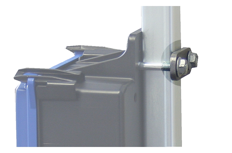
- Threaded bracket and M8 rib nut
- 2x per receiver
- 15 Nm.
Operation
This section applies to anyone who lifts loads using the crane or works nearby
Be sure to read and observe the product manual of the entire crane! The instructions given here apply in addition to the other product manuals.
Emergency stop
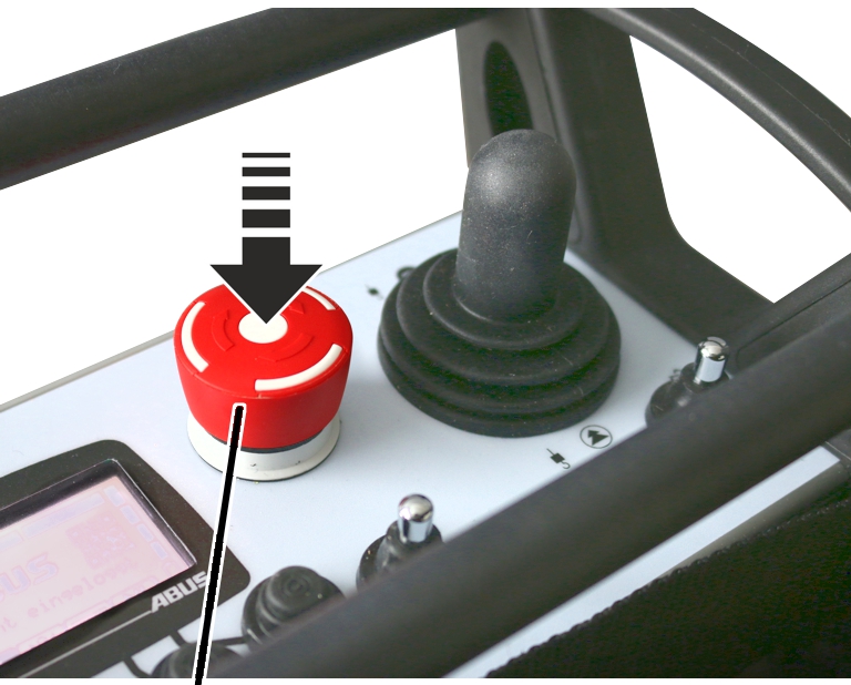
In dangerous situations with the crane:
- Press the stop button.
- The transmitter sends a stop signal to the receiver.
- The ready signal, which usually keeps transmitting a signal to the receiver, is interrupted.
- The receiver receives the stop signal and stops receiving any ready signals from the transmitter.
- The receiver activates the emergency stop on the crane.
- The crane brakes immediately and comes to a standstill.
When the danger has been eliminated:
- Turn the stop button clockwise by a quarter rotation.
- The transmitter switches on and logs into the receiver.
- If the transmitter is protected by a PIN: The window “Enter PIN” appears on the display.
- Enter the previously defined PIN for the desired protected function. See “Entering the code or PIN”.
- Press ENTER.
- The display shows “Release”.
- Press the HORN flip switch and let it go.
- The sound of the horn can be heard at the crane.
- The crane is ready for use.
Inserting rechargeable batteries
If no rechargeable batteries have been inserted:
Rechargeable batteries
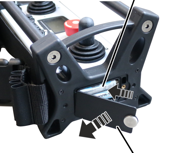
- Press the stop button.
- Unscrew the cover of the battery compartment and open it.
- Check batteries for damage.
If the batteries are damaged, properly dispose of them and replace them with new batteries!
- Observe the polarity, and insert rechargeable batteries (2x AA) into the battery compartment.
Do not insert rechargeable batteries together with single-use batteries. Single-use batteries could otherwise leak and damage the transmitter.
Do not insert batteries with different capacities. This would damage them.
- Close the battery compartment cover and screw it into place.
Carrying and holding the transmitter
Applying the hip belt
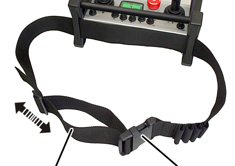
- Adjust the length of the hip belt.
- Strap on the transmitter with the hip belt and fasten the clasp.
Checking, switching on and releasing prior to beginning work
Check the following points before starting work with the crane using ABURemote. If there is any damage or problems arise, do not work with the crane; inform coworkers and supervisors.
Checking the outside of the transmitter
- Are any parts on the transmitter broken or out-of-order?
- Are rubber components on the joysticks, flip switches or buttons torn or very dirty?
Switching on
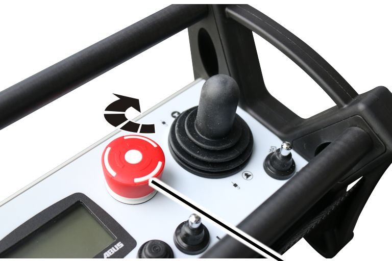
- If necessary: Switch on the entire crane using the mains switch.
- The crane and the receiver are switched on.
- The receiver is waiting for the corresponding transmitter.
- Turn the stop button clockwise by a quarter rotation.
- The transmitter switches on and the display lights up.
- With an automatic search for a radio channel: The transmitter automatically searches for a free radio channel and occupies it.
- When the transmitter is within range of the receiver, the receiver connects with the transmitter.
Only with activated PIN
Entering the PIN
If the transmitter or a certain function is protected by a PIN:
“Enter PIN” window
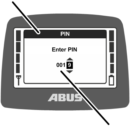
- The “Enter PIN” window is shown in the display.
- Enter the previously defined PIN for the desired protected function. See “Entering the code or PIN”.
- Press ENTER.
- The transmitter is switched on and the protected function matching the entered PIN is enabled.
There are up to four different PIN levels, each with their respective PIN:
- Level 0: Transmitter PIN code (transmitter can only be switched on with correct PIN).
- Level 1: Protected function “Override limit switch” (The function “Override limit switch” can only be selected if the correct PIN has been entered).
- Level 2: Protected load limiting system (The load limiting system is switched off when the correct PIN is entered).
- Level 3: Combination of PIN level 1 and PIN level 2.
Overview of functions and instructions for setting PIN and protected functions: See “Setting PIN for transmitter PIN code and protected functions”.
Depending on the transmitter version, the special functions can also be accessed with a key switch. See “Operating additional functions on the crane using key switches”.
Releasing the transmitter
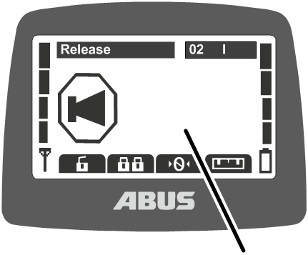
- The transmitter automatically logs back in to same the receiver it was logged in to when it was switched off.
- The display shows “Release”.
- Press the HORN flip switch and let it go.
- The sound of the horn can be heard at the crane.
- The crane is ready for use.
Only with signal lamps for radio remote control
Once the transmitter is released:
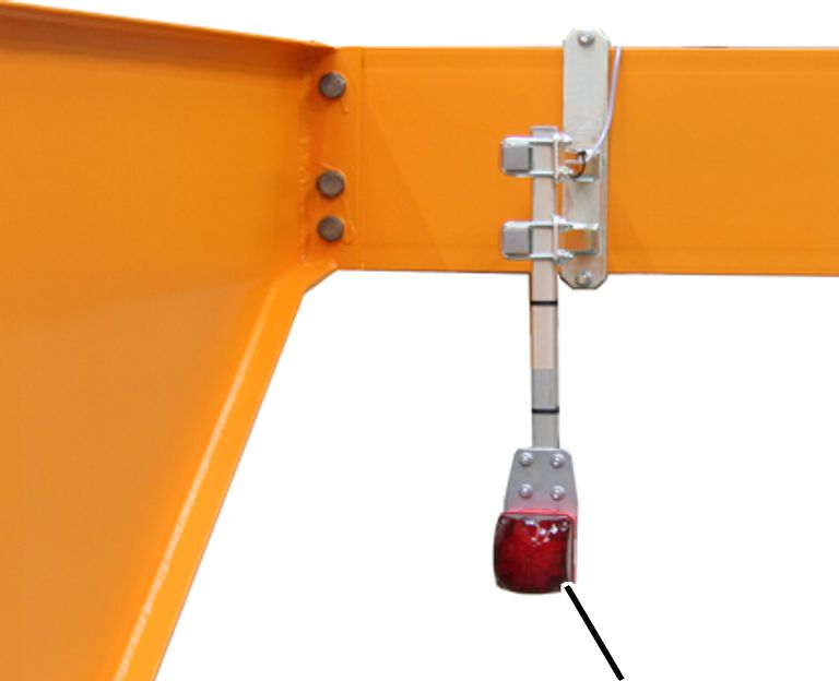
- The red signal lamp lights up.
Persons nearby thus know that a transmitter is logged in to the crane and the crane can move at any time.
Logging in the transmitter
In some situations, the transmitter does not automatically log back in to the receiver:
- The transmitter was not logged in at the time of being switched off.
- The crane is not within range of the transmitter.
- The crane was switched off in the meantime.
- The crane has since been restarted.
- Another transmitter is logged in to the crane.
- The transmitter was manually logged out beforehand.
- An automatic login was previously cancelled.
If the transmitter does not log back in automatically:
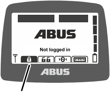
- Either:
Press the direct access button “Log in” (closed padlock).
Or:
Open the main menu with the MENU button,
open the menu “Crane operation”,
open the menu item “Log in”.
- If the transmitter or a function is protected by a PIN: The window “Enter PIN” appears on the display.
- Enter PIN. See “Entering the code or PIN”.
- The transmitter logs in to the receiver.
- The display shows “Release”.
- Press the HORN flip switch and let it go.
- The sound of the horn can be heard at the crane.
- The crane is ready for use.
Checking the stop button
Test the following before beginning work:
- Press the ‘Lift’ joystick fully.
- The load hook moves up.
- Press the stop button.
- The transmitter goes out.
- The load hook halts.
- Turn the stop button clockwise by a quarter rotation.
- The transmitter switches on and logs into the receiver.
- If the transmitter is protected by a PIN: The window “Enter PIN” appears on the display.
- Enter the previously defined PIN for the desired protected function. See “Entering the code or PIN”.
- Press ENTER.
- The display shows “Release”.
- Press the HORN flip switch and let it go.
- The sound of the horn can be heard at the crane.
- The crane is ready for use.
Operating the crane
Lifting and lowering, trolley travel, crane travel
Joystick for trolley travel and crane travelJoystick for lifting and lowering
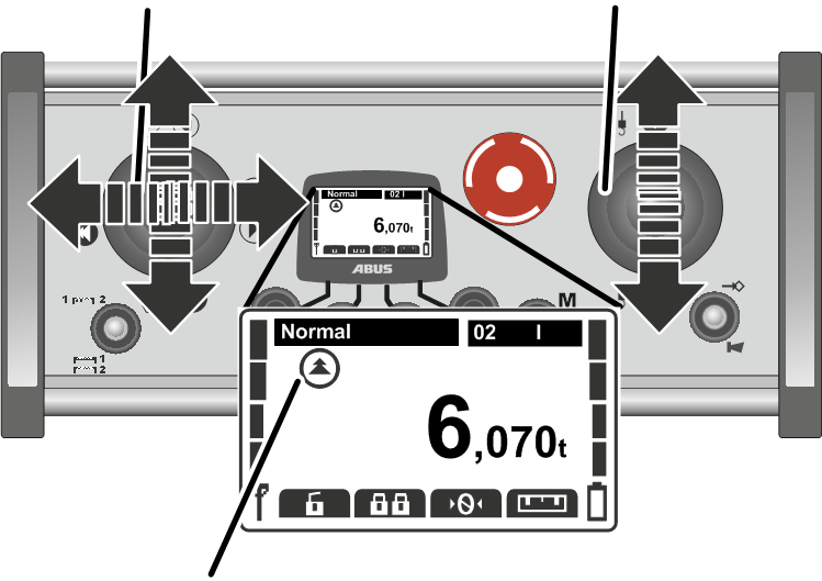
- With a two-stage joystick: Press the joystick halfway or fully to control the crane and the trolley.
With a proportional joystick: Press the joystick continuously to control the crane and the trolley.
The joystick for lifting and lowering must be pushed away from the body for lowering and be pushed towards the body for lifting. If the crane operator is carrying the transmitter with the hip belt, then the transmitter is hanging at an angle. In this case, the joystick direction is the same as the direction of the load hook.
- The direction of the crane, trolley and load hook appears on the display.
Operating a crane with two trolleys: See “Operating a crane with two trolleys”.
For a crane with one trolley, you can also switch between the displays for “I” or “II” on the transmitter, but only trolley I will be controlled.
Operating two cranes in tandem operation: See “Operating cranes in tandem operation”.
Horns
To warn other persons of danger:
HORN flip switch
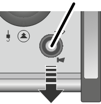
- Press the HORN flip switch.
- The sound of the horn can be heard at the crane.
Changing the radio channel
Should malfunctions occur (connection is cut off or signal quality declines):
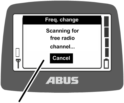
- Press the CHANNEL CHANGE flip switch.
- The transmitter disconnects the connection to the receiver.
- The receiver is waiting for the corresponding transmitter.
- The message “Scanning for free radio channel...” appears on the display.
- The transmitter scans the 433 MHz frequency range or the 868 MHz frequency range and evaluates the current radio situation in its surroundings. Based on this, the transmitter selects the most optimal radio channel for the connection.
- The receiver finds the transmitter.
- The display shows “Release”.
- Press the HORN flip switch and let it go.
- The sound of the horn can be heard at the crane.
- The crane is ready for use.
The radio channel can only be changed when the transmitter has not been set to a fixed radio channel. To set the transmitter to a fixed radio channel: See “Setting the radio channel”.
In the case of a channel change, the transmitter evaluates the current radio situation in its surroundings. If the radio situation changes during running operation, the radio channel is not automatically changed.
Should malfunctions occur (e.g. connection is cut off or signal quality declines), the channel should be changed on the transmitter. The radio situation in the vicinity of the transmitter is then re-evaluated.
If a channel change is made multiple times in brief succession:
- The radio situation is re-evaluated each time and the radio channel is changed as previously described.
- If the radio situation has not changed since the last channel change,
(e.g. because the transmitter is at the same position):
The transmitter will still change the radio channel.
Also if the evaluation of the local radio situation gives the same result as with the last channel change, the radio channel that is used is still changed. In this case, the next best radio channel is used.
In this way you can switch between the five best radio channels.
Avoiding radio interference
If the radio channel used by ABURemote is interfered with by other devices, this can lead to the connection being lost (e.g. fault 101).
ABURemote has a range of more than 100 metres, depending, for example, on the walls and objects between the transmitter and receiver. Additional factors which can limit the range include other devices with wireless technology, and ambient conditions such as weather and humidity.
Observe these tips to avoid radio interference:
- Optimise the installation site of the magnetic base antenna of the receiver. See “Planning the installation on the crane”.
- Observe the minimum distance when multiple transmitters are in use. See “Observing the minimum distance with multiple transmitters”.
- Change radio channel manually. See “Changing the radio channel”.
- Instead of automatic changing of the radio channel and additional manual changing of the radio channel, a radio channel can be fixedly set. See “Setting the radio channel”.
In this connection, a comprehensive frequency management plan should be set up for the entire hall area.
- If multiple transmitters are used in close proximity to each other, it is recommended to reduce the transmission power of all transmitters. See “Setting the transmission power of transmitter and receiver”.
- If multiple receivers are used in close proximity to each other, it is recommended to reduce the transmission power of all receivers. See “Setting the transmission power of transmitter and receiver”.
Observing the minimum distance with multiple transmitters
If multiple transmitters are operated too closely to one another, occasional radio interference could occur.
The quality of the wireless connection depends on many factors, such as the radio channel, the distance to the receiver and to other transmitters, the number of transmitters in the surroundings, other devices with wireless connections, the set transmission power, etc.
Should malfunctions occur (connection is cut off or signal quality declines):
- Maintain a distance of several metres to other transmitters.
- Reduce the transmission power of all transmitters in the nearby surroundings. See “Setting the transmission power of transmitter and receiver”.
A lower transmission power of all transmitters in the surroundings reduces the intensity of the entire radio field, which in turn reduces the mutual interference.
Standby
If no button is pressed on the transmitter within a certain time, the transmitter switches to “Standby” operating mode. This occurs both on a transmitter which is logged in and one which is logged out.
The ‘“Standby” operating mode allows the transmitter to save power and makes it safer if it has been put aside and forgotten.
The time which elapses before the transmitter changes to “Standby” can be set. See “Setting standby”.
To switch the transmitter back on:
- Press the stop button.
- Turn the stop button clockwise by a quarter rotation.
- The transmitter switches on and logs into the receiver.
- If the transmitter is protected by a PIN: The window “Enter PIN” appears on the display.
- Enter the previously defined PIN for the desired protected function. See “Entering the code or PIN”.
- Press ENTER.
- The display shows “Release”.
- Press the HORN flip switch and let it go.
- The sound of the horn can be heard at the crane.
- The crane is ready for use.
Logging out and switching off the transmitter
Logging out the transmitter
- To allow another transmitter to operate the crane in tandem operation, the transmitter must be logged out. Simply switching off a logged-in transmitter or waiting until it changes to “Standby” operating mode will not suffice.
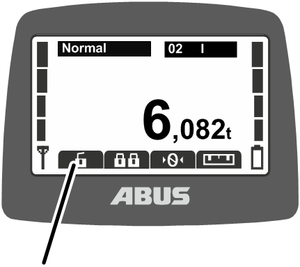
- Either:
Press the direct access button “Log out” (opened padlock).
Or:
Open the main menu with the MENU button,
open the menu “Crane operation”,
open the menu item “Log out”.
- The transmitter logs out at the crane and reverts to the “Not logged in” operating mode.
- Another transmitter can now operate the crane in tandem operation.
Logging out the transmitter from the receiver
The transmitter can also be logged out from the receiver. This is particularly useful when a transmitter is to be logged out, but is currently unavailable (e.g. locked away).
- Switch off the crane at the mains switch.
- The entire crane, including the receiver, is switched off.
- Wait at least 30 seconds.
- The receiver loses the information as to which transmitter was logged in.
- If the transmitter is switched on: Message 101 “Receiver disconnected” appears on the display and the transmitter logs out.
- Switch on the crane at the mains switch.
- Another transmitter can now log in to this crane.
Switching off the transmitter
To switch off the transmitter:
- Press the stop button.
- The transmitter goes out.
In the event of extended downtimes:
Rechargeable batteries
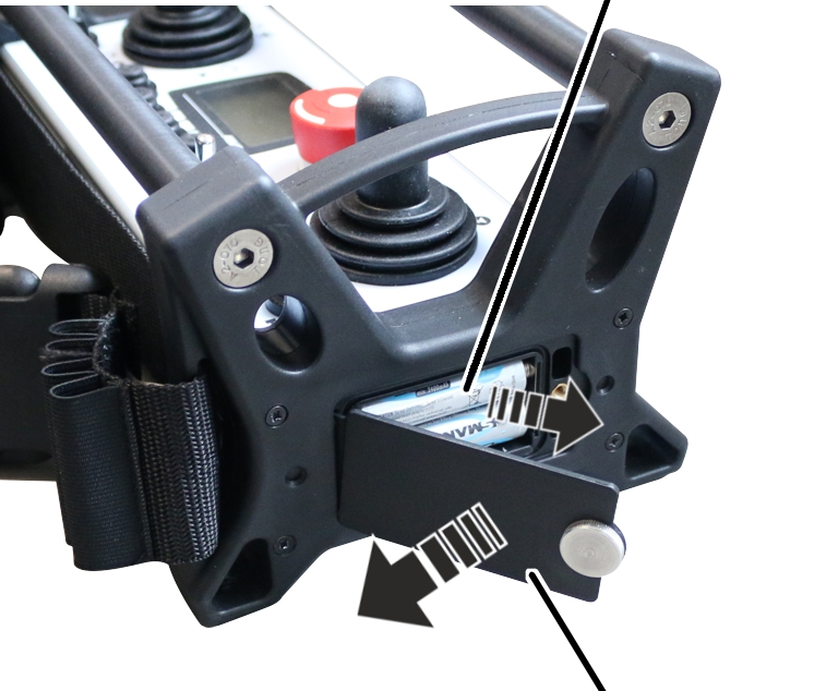
- Unscrew the cover of the battery compartment and open it.
- Remove the rechargeable batteries.
- Close the battery compartment cover and screw it into place.
Capacity indicator for rechargeable batteries
When performing normal work with the radio remote control:
Charge state gauge
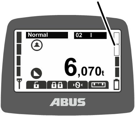
- The bar at the right-hand edge of the display shows the battery capacity remaining.
Four full bars represents a fully charged battery; four empty bars indicates the battery is empty.
Once the preset remaining battery time reaches the alarm threshold:
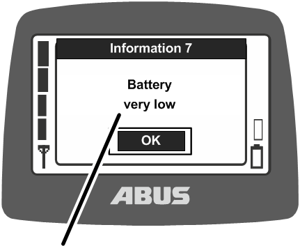
- The message “Battery very low” appears on the display.
The remaining battery time at which the message should appear can be set. See “Displaying the remaining battery time and setting the alarm”.
- No new command for crane travel, trolley travel or lifting/lowering can be issued until the message has been confirmed.
- Press ENTER.
- Set down the load.
- Change the batteries.
Changing the batteries
Rechargeable batteries
- Unscrew the cover of the battery compartment and open it.
- Remove the rechargeable batteries.
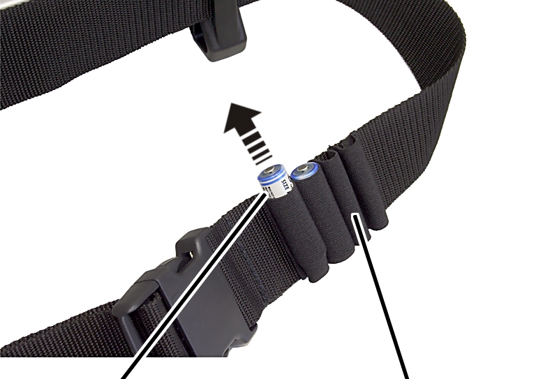
- Take the charged batteries out of the loops on the hip belt or out of the battery charger.
- Check batteries for damage.
If the batteries are damaged, properly dispose of them and replace them with new batteries!
Rechargeable batteries
- Check batteries for damage.
If the batteries are damaged, properly dispose of them and replace them with new batteries!
- Observe the polarity, and insert rechargeable batteries (2x AA) into the battery compartment.
Do not insert rechargeable batteries together with single-use batteries. Single-use batteries could otherwise leak and damage the transmitter.
Do not insert batteries with different capacities. This would damage them.
- Close the battery compartment cover and screw it into place.
Charging the batteries
The battery charger can be adapted to the local mains supply using the exchangeable connectors.
Changing the connector on the battery charger
Battery charger
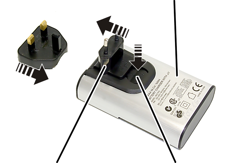
- Compare the specifications on the type plate with the local mains supply.
- Press the button on the rear of the battery charger.
- Push the connector upwards and remove it.
- Push on the connector required so it audibly clicks into place.
Charging batteries
Charging slot
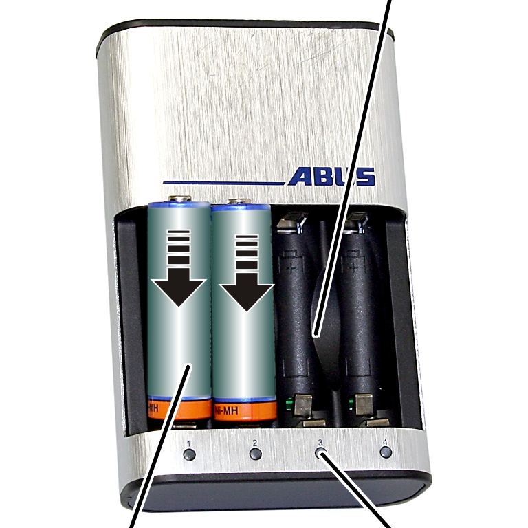
- Check batteries for damage.
If the batteries are damaged, properly dispose of them and replace them with new batteries!
- Observe the polarity and insert the batteries into the battery charger.
- Plug the battery charger into the socket.
- The charge state gauge of the battery slot concerned will flash slowly.
- The batteries will warm up.
If the charge state gauge flashes red:
- The battery is defective or a disposable battery has been inserted.
- Remove the battery and dispose of it.
- Do not dispose of rechargeable batteries with the household waste. Dispose of them in accordance with the locally applicable regulations.
After charging
The charge state gauge lights up continuously green:
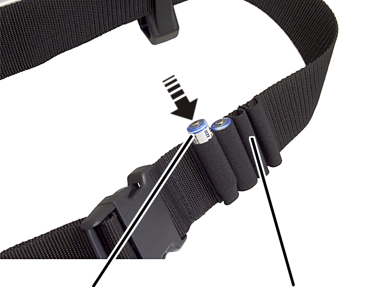
- The battery is fully charged.
- The battery charger switches over to trickle charging.
This ensures the batteries are recharged automatically as needed, remaining fully charged. This does not damage the batteries or diminish their capacity.
- When required: Remove the batteries from the charging slot.
- Insert the batteries into the loops on the hip belt for the transmitter as spare batteries.
Storing rechargeable batteries
- Store batteries in a cool (preferably below 25° C), well-ventilated location and keep them away from moisture, sources of heat and naked flames.
Temperatures over 70° C can cause the batteries to discharge!
Cleaning the transmitter
If there is slight soiling:
- Clean the transmitter with a cloth using a mild detergent solution.
If there is severe soiling:
- Clean the transmitter with a cloth using isopropanol.
Tare
Only with cranes with load display
Tare
The load display of the crane can be reset to zero using “Tare”. This allows a differential measurement to be made, e.g. in order not to include the weight of a crosshead.
This function can be opened in the menu or using a direct access button.
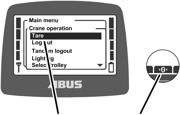
- Either:
Press the direct access button “Tare” (zero with two arrows).
Or:
Open the main menu with the MENU button,
open the menu “Crane operation”,
open the menu item “Tare”.
- Press and hold the direct access button or ENTER in the menu for about 3 seconds.
- The display of the suspended load is set to zero.
To reset the tare:
- Press the direct access button “Tare” (zero with two arrows) or open the menu item “Tare”.
- The display of the slung load shows the original value again.
Switching the crane lighting on and off
Only with crane lighting
The function “Lighting” can be used to switch the crane lighting on and off.
This function can be opened in the menu or using a direct access button.
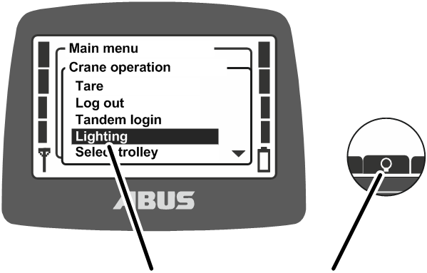
- Either:
Press the direct access button “Lighting” (light bulb).
Or:
Open the main menu with the MENU button,
open the menu “Crane operation”,
open the menu item “Lighting”.
- The crane lighting is switched on.
- To switch the crane lighting back off, press the direct access button “Lighting” again, or call up the “Lighting” menu item again in the “Crane operation” menu.
Using sway control
Only with ABUControl with sway control
The “Sway control” function considerably reduces the swinging movement of the load hook during trolley and crane travel on a crane with ABUControl. See the “ABUControl” product manual.
This function can be opened in the menu or using a direct access button.
Switch sway control on:
The sway control initially only functions on a crane with a single
trolley or on a train with multiple trolleys provided the unused trolley
is in the parking position (load hook triggers top hoist limiter).
During joint operation of several trolleys or in tandem operation, the
sway control must be separately enabled. See the ABUControl Product
Manual.
Sway control is inactive for a hook path less than 1.5 m. To use the function, the hook path must be greater than 1.5 m.
For ABURemote with individual control: If a load hook is in the highest hook position (top hoist limiter), the sway control can be switched on for the other load hook.
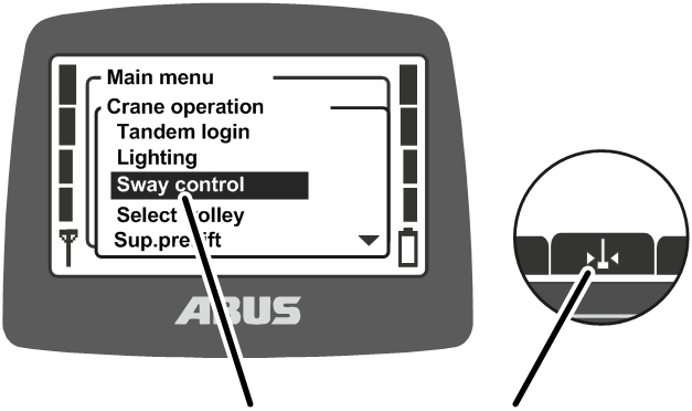
- Either:
Press the direct access button “Sway control on” (pendulum with two arrows).
Or:
Open the main menu with the MENU button,
open the menu “Crane operation”,
open the menu item “Sway control”.
ABUControl must know the length of the load lifting attachment in order for the sway control to function properly.
Menu “Sway control”
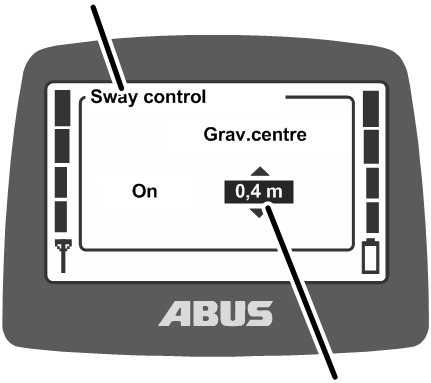
- The “Sway control” window is shown in the display.
- The last set distance is displayed.
- Estimate the distance between the load hook and the centre of gravity.
- Set the distance.
The distance can be set in increments of 0.2 m.
- Confirm the input with ENTER.
Load hook symbol
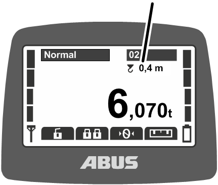
- A load hook symbol and the set distance are shown under the crane number.
Crane and trolley travel with sway control:
- Operate the crane as usual.
Avoid inching or switching back and forth fast when doing this.
- ABUControl uses the travel speeds of crane and trolley, the hook position and the length of the load lifting attachment to calculate how much the load would normally sway, and accelerates and brakes the travel motors in such a way that the swinging movement is reduced.
- The acceleration and braking distances are not substantially altered.
- The function does not compensate for external influences such as wind, impacts against the load or load hook, or manual movements.
Note
Sway control prevents the load swaying in active operation. So do not try to also prevent the load swaying by manually countersteering. This can impede or disrupt the function.
Switch sway control off:
Menu “Sway control”
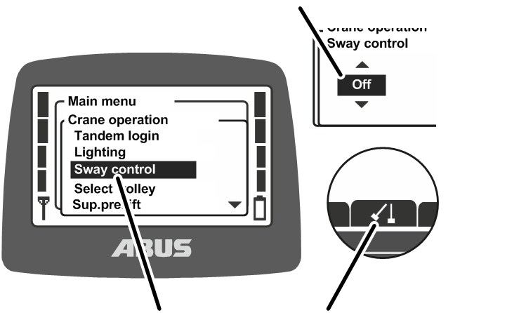
- Either:
Press the direct access button “Sway control off” (two pendulums).
Or:
Open the main menu with the MENU button,
open the menu “Crane operation”,
select the value “off” in the menu item “Sway control”,
confirm by pressing ENTER.
- The sway control is switched off.
The sway control is automatically switched off when switching between several hoists (e.g. between two trolleys on one crane).
However, the sway control can be switched back on again depending on the selected setting in ABUControl (with corrected length of the load lifting attachment).
Using the hook centring
Only for hook centring
The “Hook centring” function automatically positions the load hook vertically above the load slinging point when the load is attached. This facilitates and speeds up positioning of the trolley vertically. As long as hook centring is active the load can only be lifted at a slow lifting speed.
The hook centring can be activated and deactivated at KranOS level. See the ABUControl Product Manual.
- This function can only be activated using a direct access button. The function can only be used if a trolley is selected. The function is not available if two trolleys are selected.
- The hoist on the second or third trolley must be in the parking position (top hoist limiter is actuated by the load hook) so the trolley travel and crane travel function using the hook centring.
- If the crane and/or trolley are in the braking function range the hook centring is still available, but the lifting speed is adjusted to the low speed.
- The hook centring is inactive for a hook path less than 1.5 m. To use the function, the hook path must be greater than 1.5 m.
- Transmitters with three joysticks only:
Before the hook centring can be used, the trolley for which the hook centring is to be used must be selected using the “Select trolley“ flip switch. The other trolleys must be in the parking position (load hook triggers top hoist limiter). - Only for a transmitter with three joysticks:
The middle joystick cannot be used for the “Travel release”.
Instructions for using hook centring:
- Hook centring is an assistance function. It is intended to support the crane operator and facilitate operation. It does not release the crane operator from their duty of care. The crane may only be operated by trained personnel. The crane operator is always responsible for transporting the load safely.
- The crane operator should always stand outside the danger zone.
- Hook centring centres the load hook above the load slinging point. This does not necessarily have to be the load’s centre of gravity. An asymmetrically or incorrectly attached load will not be raised evenly by to the hook centring.
- If a heavy load hook is used for a lighter load and hook centring is used, the load can drag against the floor during lifting before the load hook has been centred over the load. The load should therefore be no lighter than 1/3 of the weight of the load hook.
Switch on hook centring:
- Attach load.
- If a long lifting tackle needs to be tightened first, first press the lift button to tighten the lifting tackle.
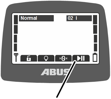
- Press and hold the direct access button “Travel release” (play and pause symbol), then press and hold the lift button.
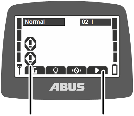
- Flashing icons for both crane axes are shown on the display.
- The load hook moves up and the hoist centres itself vertically above the load slinging point in the crane and trolley travel direction.
- The load hook then continues lifting.
As long as hook centring is active the load can only be lifted at a slow lifting speed. The slow lifting speed can be set in KranOS. See the ABUControl Product Manual.
To close hook centring:
- Release the direct access button “Travel release” (play and pause symbol) or the button for lifting.
- The hook centring is deactivated after the direct access button has been released and the crane switches to normal lifting.
Error when activating the hook centring:
If the button “Travel release” has been pressed but the hook centring is not available or only available to a limited extent because, for example, a drive axle or the lifting function is locked:
- The message “F0048: Hook assistant restricted.3” is shown on the LED matrix display.
- Lifting is also locked so a load cannot be lifted accidentally before the trolley has been centred.
Using the hook guidance
Only for hook guidance
The “Hook guidance” function allows the load hook to be moved by hand. Both the crane and the trolley follow the direction the load hook is moved by hand. In this way the crane can be moved intuitively.
- This function can only be activated using a direct access button. The function can only be used if a trolley is selected. The function is not available if two trolleys are selected.
- The hoist on the second or third trolley must be in the parking position (top hoist limiter is actuated by the load hook) so the trolley travel and crane travel function using the hook guidance.
- The hook guidance is inactive for a hook path less than 1.5 m. To use the function, the hook path must be greater than 1.5 m.
- Transmitters with three joysticks only:
Before the hook guidance can be used, the trolley for which the hook guidance is to be used must be selected using the “Select trolley” flip switch. The other trolleys must be in the parking position (load hook triggers top hoist limiter). - Only for a transmitter with three joysticks:
The middle joystick cannot be used for the “Travel release”.
Instructions for using hook guidance:
- Hook guidance is an assistance function. It is intended to support the crane operator and facilitate operation. It does not release the crane operator from their duty of care. The crane may only be operated by trained personnel. The crane operator is always responsible for transporting the load safely.
- The crane operator should always stand outside the danger zone.
- The positioning control must not be activated at the same time as the hook guidance function is otherwise not available.
To switch on hook guidance:
- Press and hold the direct access button “Travel release” (play and pause symbol).
or
Press the direct access button “Travel release” (play and pause symbol) and, press and hold any travel command button (crane travel forward, crane travel back, crane travel left, crane travel right).
If a travel command button is pressed, the direct access button can be released.
- Flashing icons for both crane axes are shown on the display.
- Hook guidance is active.
- Move the unladen load hook manually.
- The crane and trolley follow the deflection movement at the appropriate speed.
To close hook guidance:
- Release the direct access button “Travel release” (play and pause symbol) or the button for the travel command.
- The crane and trolley brake.
The hook guidance can be used as long as the direct access button “Travel release” (play and pause symbol) or the button for the travel command are pressed.
If the load hook swings strongly back and forth:
- The hook guidance will be stopped automatically after the unladen load hook has swung twice. This prevents it swinging up.
- Crane travel and trolley travel are stopped.
Error when activating the hook guidance:
If the button “Travel release” has been pressed but the hook guidance is not available or only available to a limited extent.
- The message “F0048: Hook assistant restricted.3” is shown on the LED matrix display.
Performing teach-in with an electronic hoist limit switch
Only with chain hoists with an electronic hoist limit switch
With a chain hoist with electronic hoist limit switch, the “Teach-In” function can be used to set the switching point of the hoist limit switch. See the “Hoist limit switch” documentation.
This function can be opened in the menu or using a direct access button.
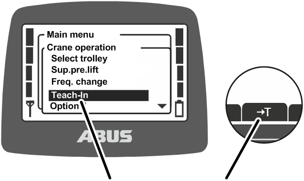
- Either:
Press and hold the direct access button “Teach-In” (T with arrow) until the position is saved.
Or:
Open the main menu with the MENU button,
open the menu “Crane operation”,
open the menu item “Teach-In” and press and hold ENTER until the position is saved.
- The current position of the load hook is saved.
Overriding limit switch for a bypass control
Only when overriding limit switch
Using the “Limit switch” function, the limit switch of a bypass control (e.g. for tall machines over which the crane is usually not allowed to travel) can be overridden. The crane can then be moved into the blocked area at a slow speed (e.g. to set up the machine).
This function can only be opened using a direct access button.
Only with protected function “Override limit switch”
The function “Override limit switch” is protected by a PIN or a key switch.
Unlocking and locking protected functions
To unlock a protected function:
- Either:
For a function protected by a PIN: When switching on or logging in the transmitter, enter the correct PIN for PIN level 1 or PIN level 3. See “Entering the PIN”.
Or:
For function protected by key switch: Insert the key in the switch and turn it. See “Operating additional functions on the crane using key switches”.
- The protected function is unlocked.
- The direct access button has a black background. The protected function “Override limit switch” can now be used.
To lock a protected function:
For function protected by PIN: Log out or switch off transmitter. When switching on or logging in, the correct PIN for PIN level 1 or PIN level 3 must be entered again. See “Entering the PIN”. Or: For function protected by key switch: Turn the key switch and pull it out.
|
|---|
Overriding limit switch
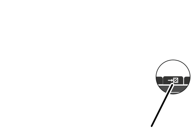
- Allow the crane to travel right up to the blocked area.
- The crane halts.
- Press and hold the direct access button “Limit switch” (hatched wall with arrow).
- While pressing the direct access button “Limit switch”, move the crane into the blocked area.
Positioning assistance: Approaching positions
Only for positioning assistance
The positioning assistance enables crane and trolley to halt at previously specified positions within the traversing range.
This function can only be opened using a direct access button.

- Move crane or trolley up to the point just in front of the desired position.
- Press the direct access button “Positioning” (vertical line with arrows) and hold it.
- Now move the crane or trolley only at low speed.
- Continue moving the crane with the “Positioning” direct access button pressed.
- As soon as the position is reached, the crane or trolley halts.
- The “Position reached” signal lamp lights up.
Positioning control on ABUControl: Teaching in positioning points
Only with positioning control on ABUControl
The “Teach in positioning points” function enables positioning points to be taught in for both “Manual positioning control” and “Semi-automatic linear positioning control” (LIN). A maximum of 127 positioning points can be taught in.
These positioning points can be approached directly later with manual or “Semi-automatic linear positioning control” (LIN). The two options vary in how the crane moves to the saved position. See “Positioning assistance: Approaching positions” or “Positioning control on ABUControl: Teaching in positioning points and route point”.
The positioning points and the height to which load hook travels when approaching the positioning points can then be modified in KranOS. See the “ABUControl” product manual.
Teaching in positioning points
Teaching in positioning pointsPositioning point
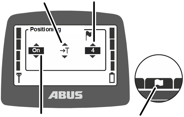
- Move to required position (positioning point).
- Open “Positioning” using the direct access button (flag).
- The menu “Positioning” appears.
- Select “on” in the menu “Positioning” to select the “Positioning point” teach mode (straight arrow with T) and the positioning point.
Note: The modes to move to the positions (hand or flag) as well as the teach-in positioning points function (symbol with T) can be selected via the menu “Positioning”.
- Confirm by pressing the ENTER button.
- The teach mode is now active.
- The display shows the normal operating mode.
Teaching in positioning points display
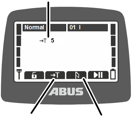
- Press direct access button “Teach-In” and hold for 5 s.
- The horn sounds.
- The position is now saved.
- Close the Teach-In positioning mode using the direct access button (drooping flag).
- Repeat the procedure to teach in further positioning points.
Select another positioning point when doing this to teach in a new position.
If a positioning point is selected on which a position has already been taught in, the already saved position will be overwritten.
After a positioning point has been taught in, the Teach-In positioning mode must always be closed using the direct access button (drooping flag).
Positioning control on ABUControl: Teaching in routes
Only with positioning control on ABUControl
Up to 16 routes with 8 route points each can be taught in for the “Point-to-point positioning control (PTP)” using the “Teach-In PTP” function.
The route points can be sequentially approached later in the order in which they were saved using “Point-to-point positioning control”.
Teaching in the route
The PTP positioning mode can only then be started if the crane and trolley are at the first or last route point. Here the hook position is irrelevant. It is therefore sensible to teach in the first or last route point as a positioning point as well so as to allow easy navigation to it later and the PTP positioning mode can easily start from there.
- Approach and teach in the first or last route point as a positioning point. See “Positioning control on ABUControl: Teaching in positioning points”.
- The load hook is at the first or last route point of the routes to be saved as described below.
Teach-In PTPRoute
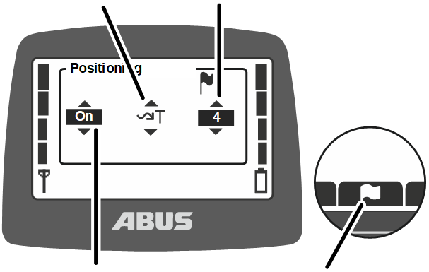
- Open “Positioning” using the direct access button (flag).
- The menu “Positioning” appears.
- Select “on” in the menu “Positioning” to select the “PTP” teach mode (curled arrow with T) and the route.
Note: The modes to move to the route points (hand or flag) as well as the route points teach-in function (symbol with T) can be selected via the menu “Positioning”.
- Confirm by pressing the ENTER button.
- The teach mode is now active.
- The display shows the normal operating mode.
Teach-In PTP display
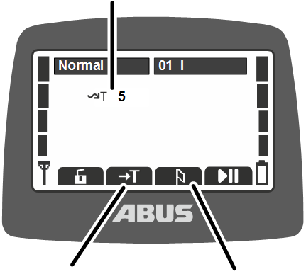
- Press direct access button “Teach-In” and hold for 5 s.
- The horn sounds.
- The first route point is now saved.
- Navigate to the following route points and save them using the direct access button “Teach-In” (press and hold 5 s).
The last point on the route is the last saved route point.
The number of the current route is shown on the display, but the individual route points are not.
- Close PTP Teach mode using the “Positioning” direct access button (drooping flag).
- Repeat the procedure to teach in further routes.
Select another route to teach in a new route.
If a route is selected on which route points have already been taught in, the already saved route will be completely overwritten as soon as the first new route point has been taught in.
After a route has been taught in, the Teach-In positioning mode must always be closed using the direct access button (drooping flag).
Positioning control on ABUControl: Teaching in positioning points and route point
There are three positioning modes in the ABUControl positioning control:
- In “Manual positioning control”, a saved positioning point is selected. The operating commands towards this positioning point must then be given manually (as with normal crane operation). The corresponding crane axis stops as soon as the position in the crane travel direction or trolley travel direction and for lifting/lowering has been reached. It is not possible to overrun the point.
- In “Semi-automatic linear positioning control (LIN)”, pressing the button “Lift” moves the crane semi-automatically to the saved positioning point on all crane axes.
- Up to 16 routes with a maximum of 8 route points can be taught in using “Point-to-point positioning control (PTP)”. The crane then follows the route semi-automatically. To start positioning control, the crane must be at the first or last route point. Here the hook position is irrelevant. From the first route point, the crane follows the saved route points sequentially in ascending order. From the last route point, the crane follows the stored route points sequentially in descending order (i.e. backwards).
Information on using positioning control:
- Positioning control is an assistance function. It is intended to support the crane operator and facilitate operation. It does not release the crane operator from their duty of care. The crane may only be operated by trained personnel. The crane operator is always responsible for transporting the load safely.
- Make sure when using the positioning control that the route can be freely navigated and no obstacles stand in the path or move into the path during use.
- ABUControl sway control can be used in parallel to positioning control. Sway control must be activated before starting positioning control.
The sway control status cannot be changed when PTP positioning control is activated or when teaching in the route for PTP positioning control. Access to the sway control function is locked in these modes (direct access buttons and menu).
- Switching between individual/together when PTP positioning control is activated or when teaching in the route for PTP positioning control causes an error and the procedure cannot be completed correctly.
- Super-precision lifting cannot be activated or deactivated when PTP positioning mode and Teach-In PTP are activated.
- Obstacles stored in the ABUControl building profile control are taken into account when positioning control is active and, if necessary, bypassed if bypassing by stopping an individual axis is possible.
- If multiple hoists are selected during positioning control, the hoist with the lowest number is positioned. All other hoists move with it synchronously. If the crane is in tandem operation positioning occurs based on the leading crane.
- “Point-to-point positioning control (PTP)” is not a track or route control system in the form of automation technology (e.g. CNC machines). The path between the route points is therefore not monitored.
- Once a route has been taught in, it must be tested in every case to ensure the crane follows the route as expected.
Selecting positioning mode
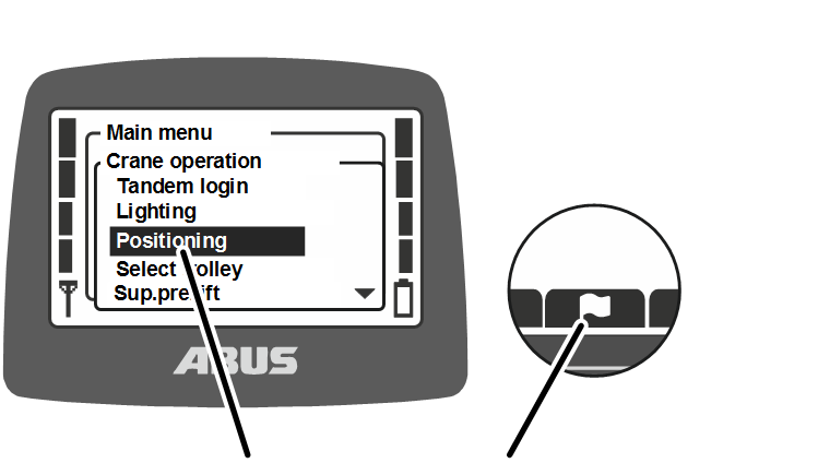
- Either:
Press direct access button “Positioning” (flag).
Or:
Open the main menu with the MENU button,
open the menu “Crane operation”,
Open the menu item “Positioning”.
- The menu item “Positioning” is displayed.
Positioning mode
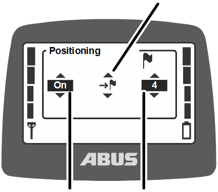
- Select the value “on” in the menu item “Positioning”,
- Select positioning mode:
- “Manual positioning control”: Hand
- “Semi-automatic linear positioning control (LIN)”: Straight line with flag
- “Point-to-point positioning control (PTP)”: Inclined arrow with flag.
Note: The modes to move to the positioning points (hand or flag) as well as the positioning points teach-in function (symbol with T) can be selected via the menu “Positioning”. See “Positioning control on ABUControl: Teaching in positioning points” or “Positioning control on ABUControl: Teaching in routes”.
- Select the number of the positioning point or the route to which to navigate.
- Confirm by pressing the ENTER button.
- The positioning mode is now selected and activated.
- For LIN and PTP only: The symbols for the three crane axes in the display flash.
- The message “F0037: Positioning: Active” is shown on the LED matrix display on the crane.
- Only for signal lamp: The “Positioning” signal lamp flashes or lights up.
Moving to position
Only with manual positioning control
In manual positioning control, the individual crane axes move to the saved positioning point and stay there. However, the crane axes must be operated manually.
Manual positioning display
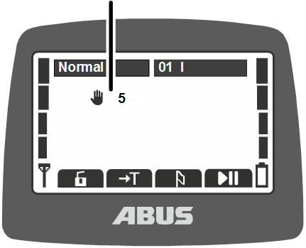
- Move the crane and trolley towards the saved positioning point using the crane travel and trolley travel buttons.
- Once the crane and/or trolley have reached the saved positioning point, the corresponding crane axis stops.
- Press and hold “Lift” or “Lower”.
- The load hook stops once it has reached the saved positioning point.
- “Manual positioning control” remains active.
- The message “F0038: Positioning: Position reached” is shown on the LED matrix display on the crane.
- Only for signal lamp: The “Positioning” signal lamp goes out.
Note
Only activate the manual positioning control once in the immediate vicinity of the saved positioning point, as possible obstacles between the load hook and the saved positioning point cannot be bypassed when positioning control is activated.
Only with semi-automatic linear positioning control (LIN)
In “Semi-automatic linear positioning control (LIN)”, the crane moves
semi-automatically to the saved positioning point in all crane axes.
Press and hold the “Lift” button on the transmitter to do this.
The saved positioning points can be viewed and edited in KranOS. See the
“ABUControl” product manual.
Start positioning:
LIN positioning display
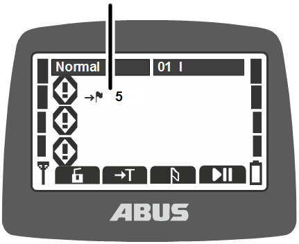
- Press and hold the “Lift” button and briefly press the horn at the same time.
The horn enables the release signal so that the crane does not immediately start positioning control when the lift button is pressed and unexpectedly move on all crane axes, if the positioning control is activated. This ensures that positioning control cannot be started accidentally.
- The crane raises to the highest hook position or to the positioning height specified in KranOS.
- The crane and trolley then travel on the direct path to the taught-in positioning point.
- The crane and trolley stop once they have reached the saved positioning point.
- The load hook is directly lowered to the target position at the saved crane and trolley position.
- The load hook stops once it has reached the saved positioning point.
- “Semi-automatic linear positioning control (LIN)” remains active.
- The message “F0038: Positioning: Position reached” is shown on the LED matrix display on the crane.
- Only for signal lamp: The “Positioning” signal lamp goes out.
To stop the hoisting procedure at the required position:
If the load hook does not lift to the highest hook position when approaching the positioning point, but rather stays in another position before then moving to the destination:
- When lifting (as previously described): Press the trolley travel left or right button.
- The load hook brakes.
- Positioning will continue at the current hook position (as described before).
Increase or reduce the travel speed:
To increase or reduce the travel speed when approaching a position:
- To accelerate: Press the button “Lift” into the second position.
- To brake: Release the “Lift” button.
- To maintain the current speed: Press and hold the button “Lift” in the first position.
Only for “Point-to-point positioning control (PTP)”
The crane follows a straight route semi-automatically in the PTP positioning control. Press and hold the “Lift” button on the transmitter to do this.
The PTP positioning is started at the first or last route point. To navigate this route point smoothly, teaching in the first or last route point as a positioning point and then moving to it first are recommended. See “Positioning control on ABUControl: Teaching in positioning points”.
Start positioning:
PTP positioning display
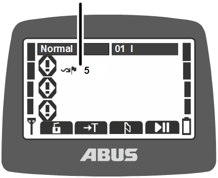
- Press and hold the “Lift” button and briefly press the horn at the same time.
The horn enables the release signal so that the crane does not immediately start positioning control when the lift button is pressed and unexpectedly move on all crane axes, if the positioning control is activated. This ensures that positioning control cannot be started accidentally.
- If the next taught in route point is above the current hook position: The crane lifts up to the taught in position.
- The crane and trolley then travel on the direct path to the first taught-in route point.
- The crane and trolley stop once they have reached the saved route point.
- If the next taught in route point is below the current hook position: The crane first moves and then lowers at the next taught in route point.
- The load hook stops once it has reached the saved route point.
- The “PTP positioning control” is still active.
- The message “F0038: Positioning: Position reached” is shown on the LED matrix display on the crane.
- Only for signal lamp: The “Positioning” signal lamp goes out.
Switching off positioning
The positioning control must be closed after the position or route has been reached, either manually using the direct access button “Positioning” (drooping flag) or using the menu as the positioning control remains activated until it is deactivated.
“Off” value
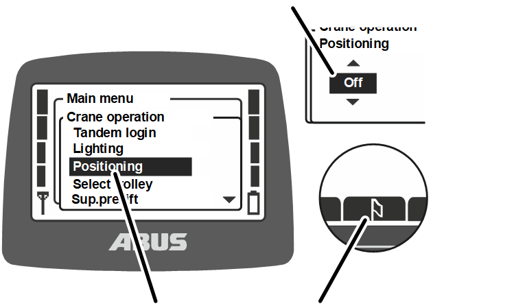
- Either:
Press direct access button “Positioning” (drooping flag).
Or:
Open the main menu with the MENU button,
open the menu “Crane operation”,
Open the menu item “Positioning”.
Select the value “off” in the menu item “Positioning”,
Confirm by pressing the ENTER button.
- Positioning control is switched off. The crane can be operated manually as usual.
Switching super-precision lifting on and off
Only with super-precision lifting
The function “Sup.pre.lift” switches the super-precision lifting on the hoist on and off. In super-precision lifting, the 12-pin winding unit of the dual-speed hoist motor is controlled. The maximum lifting speed in this mode is very low, enabling an extremely accurate positioning of the load.
This function can be opened in the menu or using a direct access button.
Switching on super-precision lifting:
Menu “Sup.pre.lift”
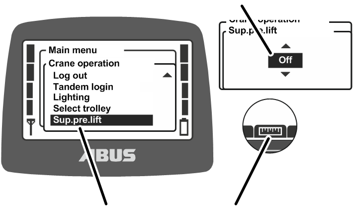
- Let go of the joystick and wait until the crane comes to a standstill.
- Either:
Press the direct access button “Sup.pre.lift on” (ruler with detailed scale).
Or:
Open the main menu with the MENU button,
open the menu “Crane operation”,
select the value “on” in the menu item “Sup.pre.lift”,
confirm by pressing ENTER.
- The super-precision lifting is switched on. The hoist can now be used for super-precision lifting.
Switching off super-precision lifting:
Menu “Sup.pre.lift”
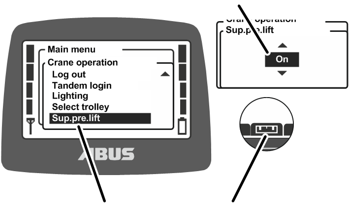
- Let go of the joystick and wait until the crane comes to a standstill.
- Either:
Press the direct access button “Sup.pre.lift off” (ruler with detailed scale).
Or:
Open the main menu with the MENU button,
open the menu “Crane operation”,
select the value “off” in the menu item “Sup.pre.lift”,
confirm by pressing ENTER.
- Super-precision lifting is switched off. The hoist can now be used for normal lifting. The hoist can now be used for super-precision lifting.
When there are two trolleys on the crane: The super-precision lifting is always switched on and off for the trolleys which are currently being operated using the transmitter.
Switching load limiting system on and off
Only with protected load limiting system
The crane has a load limiting system. This only enables the crane to lift with the maximum load capacity if the load limiting system is switched off. Otherwise (with the load limiting system switched on), only working with reduced maximum load capacity is enabled.
The load limiting system is protected by a PIN or a key switch.
Operating the crane with load limiting system switched on:
- Either:
For a load limiting system protected by a PIN: When switching on or logging in the transmitter, enter the correct PIN for PIN level 0 or PIN level 1. See “Entering the PIN”.
Or:
For load limiting system protected by key switch: Use transmitter without actuating the key switch.
- The load limiting system is switched on. The crane can now only lift with a reduced maximum load capacity.
Symbol “Load limiting system is switched on”
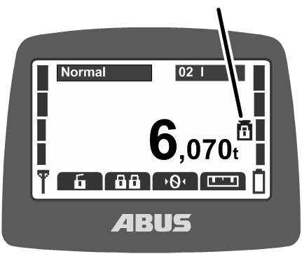
- A symbol (weight with closed padlock) is shown on the display to indicate the load limiting system is switched on.
Switching load limiting system off:
- Either:
For a load limiting system protected by a PIN: When switching on or logging in the transmitter, enter the correct PIN for PIN level 2 or PIN level 3. See “Entering the PIN”.
Or:
For load limiting system protected by key switch: Insert the key in the switch and turn it. See “Operating additional functions on the crane using key switches”.
- The load limiting system is switched off. The crane can now lift with maximum load capacity.
Symbol “Load limiting system is switched off”
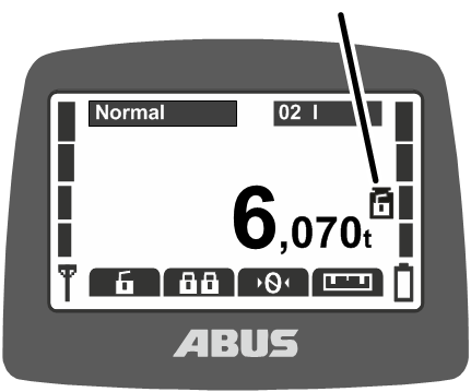
- A symbol (weight with opened padlock) is shown on the display to indicate the load limiting system is switched off.
To switch load limiting system on:
- Either:
For load limiting system protected by PIN: Log out or switch off the transmitter, or press the stop button.
If the transmitter is not logged out or switched off, the load limiting system is automatically switched on after elapse of the standby time.
Or:
For load limiting system protected by key switch: Turn the key switch and pull it out.
- The load limiting system is switched on. The crane can now only lift with a reduced maximum load capacity.
Symbol “Load limiting system is switched on”
- At the next use of the transmitter without input of a correct PIN for PIN level 2 or 3: A symbol (weight with closed padlock) is shown on the display to indicate the load limiting system is switched on.
Rotating the load hook
For rotation mechanisms only
The load hook can be rotated electrically using a rotation mechanism.
This function can be operated using a joystick.
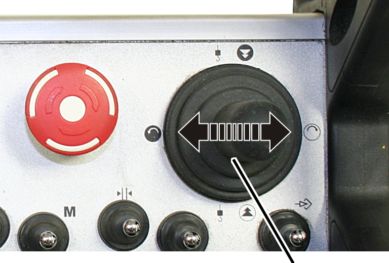
- Press the joystick sideways to rotate the load hook.
Operating additional functions on the crane using flip switches
Only with cranes with additional functions via flip switches
Individual additional functions on the crane can be controlled via additional flip switches.
These can only be controlled using the additional flip switches; there is no menu item in the menu and they cannot be allocated to a direct access button.
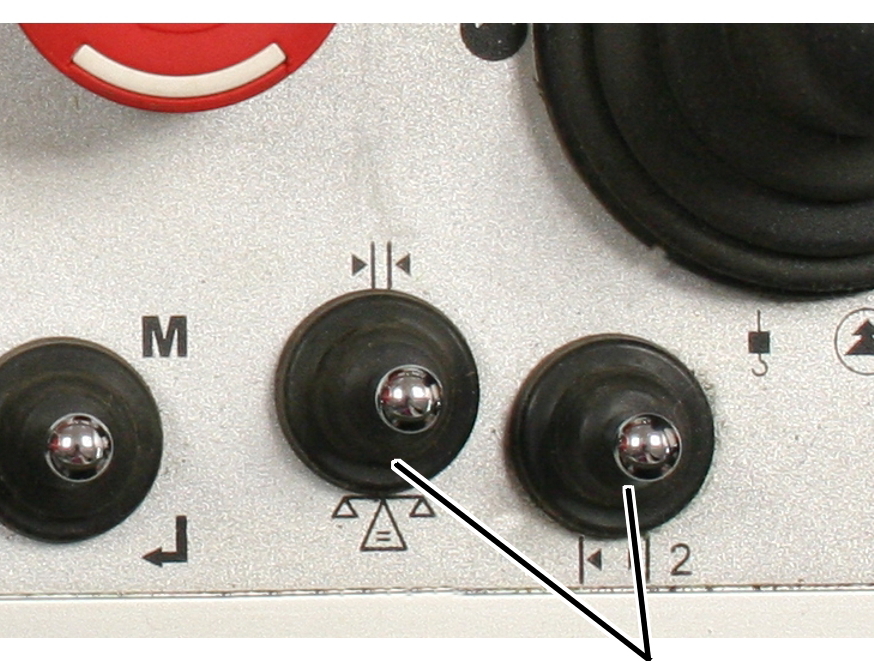
- Press the flip switch on the transmitter in the direction of the respective symbol.
- The additional function is activated.
Operating additional functions on the crane using key switches
Only with cranes with additional functions via key switches
Individual additional functions on the crane can be controlled via key switches.
These can only be controlled using the key switches; there is no menu item in the menu and they cannot be allocated to a direct access button.
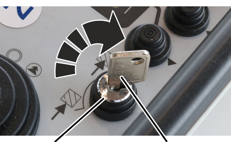
- Insert the key.
- Turn the key switch in the direction of the respective symbol.
- The additional function is activated.
Operating functions on the crane using the electronic key switch
For transmitters with electronic key switch only
Individual additional functions on the crane can be controlled via electronic key switches.
These can only be controlled using the electronic key switches; there is no menu item in the menu and they cannot be allocated to a direct access button.
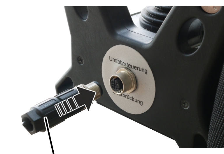
- Screw in the electronic key switch.
- The corresponding function is switched on the crane.
Operating a crane with two trolleys
Only with two trolleys
Switching between trolley I and trolley II
With two trolleys on one crane, it is possible to switch back and forth between trolley I and trolley II.
After switching on the crane, the trolley is selected that was also selected when switching off.
For a crane with one trolley, you can also switch between the displays for “I” or “II” on the transmitter, but only trolley I will be controlled.
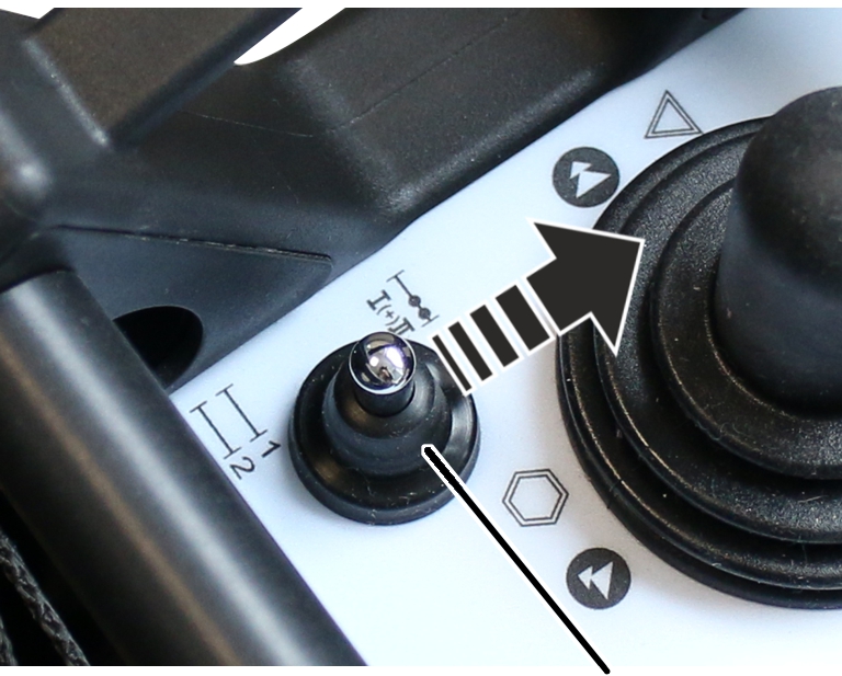
- Either:
Press the flip switch “Select trolley” once or twice until the desired trolley appears on the display.
If the selection mode “Safe” is set in the service menu: Press and hold the flip switch “Select trolley” and then also confirm with the ENTER button.
Or:
Open the main menu with the MENU button,
open the menu “Crane operation”,
select the desired trolley in the menu item “Select trolley”,
confirm by pressing ENTER.
Trolley selected
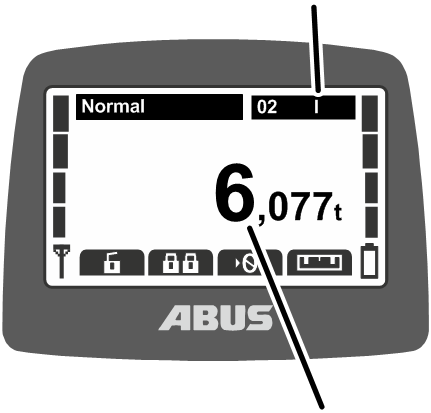
- The selected trolley is shown on the display.
- The load of the selected trolley is indicated on the display.
- Press the joystick to control the selected trolley.
Only with joint operation
Switching over to joint operation
On a crane with joint operation, it is also possible to switch back and forth between trolley I and trolley II in joint operation of both trolleys.
- Either:
Press the flip switch “Select trolley” once or twice until trolley I+II appears on the display.
If the selection mode “Safe” is set in the service menu: Press and hold the flip switch “Select trolley” and then also confirm with the ENTER button.
Or:
Open the main menu with the MENU button,
open the menu “Crane operation”,
select the value “I+II” in the menu item “Select trolley”,
confirm by pressing ENTER.
Trolley I+II
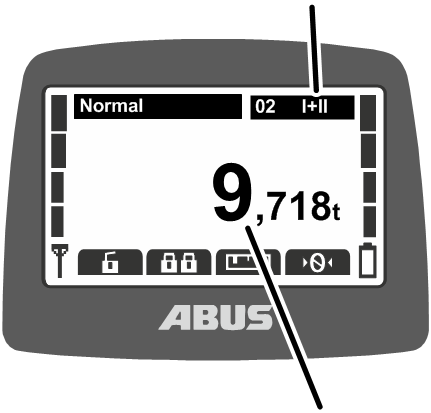
- Trolley I+II appears on the display.
- The total load on trolley I and II appears on the display.
- Press the joystick to operate trolley I and II at the same time.
Operating a crane with two trolleys using ABURemote with individual control
Only with individual control
Operating trolleys
The transmitter has its own joystick for each trolley. This enables both trolleys to be controlled independently of one another. Trolley I, for example, can lift and move to the left while trolley II is lowering and moving to the right.
Joystick for trolley II
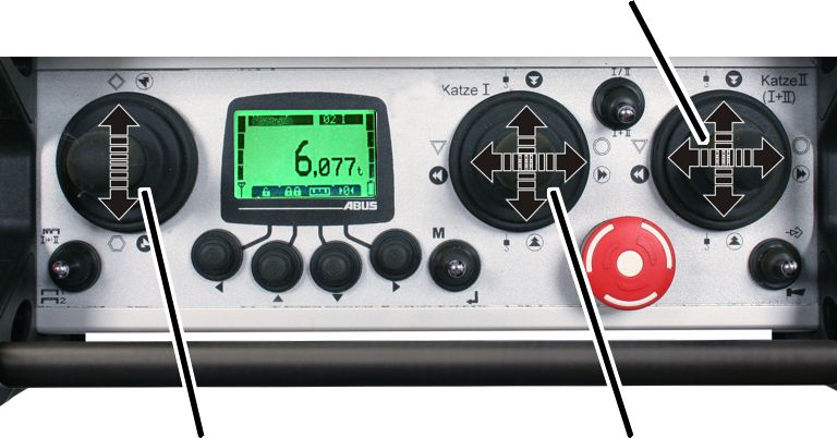
- Press the left-hand joystick to move the crane.
- Press the middle joystick to operate trolley I.
- Press the right-hand joystick to operate trolley II.
- No symbols for trolley travel and lifting/lowering appear on the display.
Displaying the load
The flip switch “Select trolley” allows you to select the trolley for which the load display on the transmitter should apply.
Displaying the load for trolley I:
After switching on the crane, the load display is initially selected for trolley I.
Load display for trolley I
- Trolley I appears on the display.
- The load on trolley I appears on the display.
Displaying the load for trolley II:
Load display for trolley II
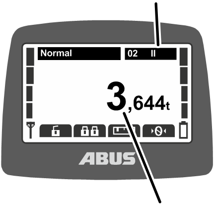
- Press the “Select trolley” flip switch.
- Trolley II appears on the display.
- The load on trolley II appears in the display.
Displaying the total load:
Load display for trolley I+II
- Press the “Select trolley” flip switch again.
- Trolley I+II appears on the display.
- The total load on trolley I and II appears on the display.
Displaying the load for trolley I again:
- Press the “Select trolley” flip switch again.
- Trolley I and the load on trolley I appear in the display again.
Only with switching over to joint operation
Switching between individual operation and joint operation
With a transmitter with switching to joint operation, it is possible to switch back and forth between individual control and joint operation. This allows switching not only to individual operation but also to joint operation of both trolleys.
To switch over to joint operation:
Flip switch
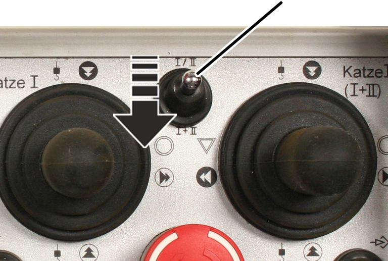
- Set flip switch to I*II (joint operation).
Joysticks for trolley I and II
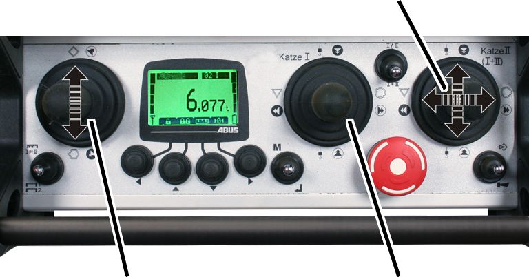
- Press the left-hand joystick to move the crane.
- The middle joystick does not have a function.
- Press the right-hand joystick to operate trolley I and II together.
- The symbols for trolley travel and lifting/lowering appear on the display.
Switching back to individual operation:
Flip switch
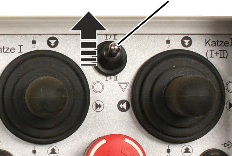
- Set the flip switch to I/II (individual control).
Joystick for trolley II
- Press the left-hand joystick to move the crane.
- Press the middle joystick to operate trolley I.
- Press the right-hand joystick to operate trolley II.
- No symbols for trolley travel and lifting/lowering appear on the display.
Operating cranes in tandem operation
With ABURemote, two cranes can be controlled jointly in tandem operation as well as in individual operation, for example, to attach a load on one crane while the other crane is blocked to prevent it being accidentally used by another crane operator.
For cranes with two trolleys in tandem operation: All functions concerning two trolleys function exactly the same way as described previously. See “Operating a crane with two trolleys”.
Only with tandem operation
Activating tandem operation
To allow cranes to be operated in tandem operation:
- The transmitter must be logged in to the crane. See “Checking, switching on and releasing prior to beginning work”.
- A transmitter may not be logged in to the second crane being operated in tandem operation. See “Logging out and switching off the transmitter”.
Logging in to the second crane
First, the transmitter must be logged in to the second crane.
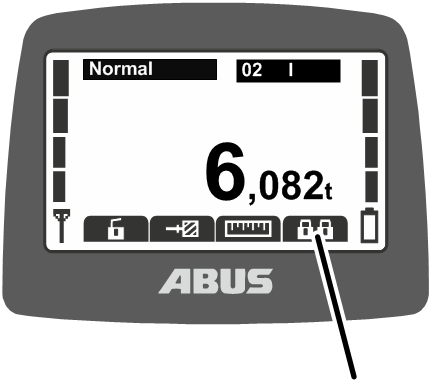
- Either:
Press the direct access button “Tandem login”.
Or:
Open the main menu with the MENU button,
open the menu “Crane operation”,
open the menu item “Tandem login”.
- If the transmitter is within range of the second receiver, the second receiver will find the transmitter.
- The transmitter logs in to the second receiver.
Release signalCrane numbers of both cranes
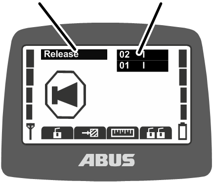
- The numbers of both cranes appear on the display.
- The display shows “Release”.
- Press the HORN flip switch and let it go.
- The sound of the horn can be heard at the crane.
- The crane is ready for use.
Operating the cranes jointly and displaying the load
After the tandem login, both cranes are automatically selected for tandem operation.
To operate the first and second crane together:
First craneSecond crane
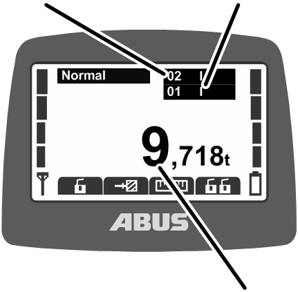
- The crane numbers of the first and second cranes appear on the display below each other with black backlighting.
- The total load of the first crane and second crane appear on the display.
- Press the joystick to operate the first crane and the second crane at the same time.
Switching between first and second crane in individual operation and displaying the load
With tandem operation switched on, it is possible to switch back and forth between the cranes in individual operation, for example, to attach a load.
Switching over to individual operation for the first crane:
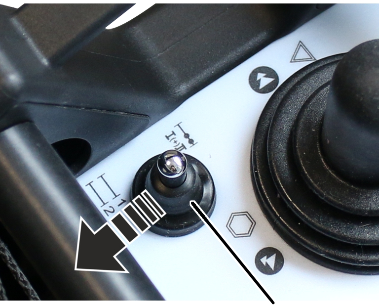
- Either:
Press the flip switch “Select crane”.
If the selection mode “Safe” is set in the service menu: Press and hold the flip switch “Select crane” and then also confirm with the ENTER button.
Or:
Open the main menu with the MENU button,
open the menu “Crane operation”,
select the crane number of the first crane in the menu item “Select crane”,
confirm by pressing ENTER.
First crane
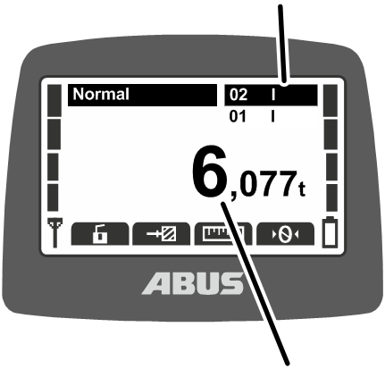
- The number of the first crane appears on the display with black backlighting.
- The load on the first crane appears on the display.
- Press the joystick to operate only the first crane.
Switching over to individual operation for the second crane:
- Either:
Press the “Select crane” flip switch again.
If the selection mode “Safe” is set in the service menu: Press and hold the flip switch “Select crane” and then also confirm with the ENTER button.
Or:
Open the main menu with the MENU button,
open the menu “Crane operation”,
select the crane number of the second crane in the menu item “Select crane”,
confirm by pressing ENTER.
Second crane
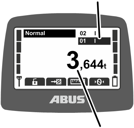
- The number of the second crane appears on the display with black backlighting.
- The load on the second crane appears in the display.
- Press the joystick to operate only the second crane.
Switching back to tandem operation
To operate the first and second crane jointly:
- Either:
Press the “Select crane” flip switch again.
If the selection mode “Safe” is set in the service menu: Press and hold the flip switch “Select crane” and then also confirm with the ENTER button.
Or:
Open the main menu with the MENU button,
open the menu “Crane operation”,
Select the crane numbers of both cranes in the menu item “Select crane” and confirm with the ENTER button.
Both cranes
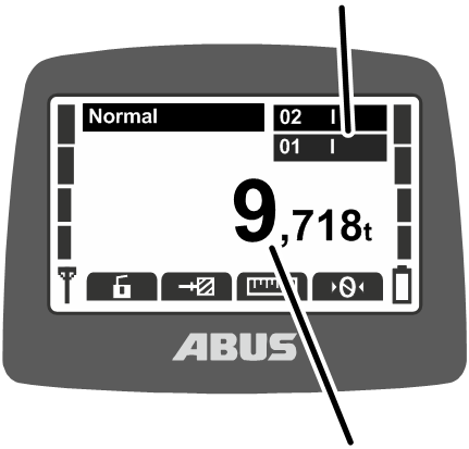
- The crane numbers of the first and second cranes appear on the display below each other with black backlighting.
- The total load of the first crane and second crane appear on the display.
- Press the joystick to operate the first crane and the second crane at the same time.
Logging out from the second crane
To end tandem operation, the second crane must be logged out of the transmitter. The second crane can then also be used again by another transmitter.
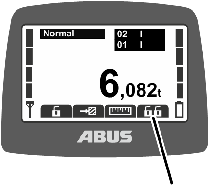
- Either:
Press the direct access button “Tandem logout”.
Or:
Open the main menu with the MENU button,
open the menu “Crane operation”,
open the menu item “Tandem logout”.
- The transmitter logs out from the second receiver.
- The display shows “Release”.
- Press the HORN flip switch and let it go.
- The sound of the horn can be heard at the crane.
- The crane is ready for use.
Logging out from both cranes
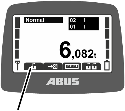
- Either:
Press the direct access button “Log out”.
Or:
Open the main menu with the MENU button,
open the menu “Crane operation”,
open the menu item “Log out”.
- The transmitter logs out from the second receiver.
- The transmitter logs out from the first receiver.
- The transmitter switches to the operating mode “Not logged in”.
Maintenance
This section applies to anyone who maintains, repairs or modifies the crane.
The end user of the crane is responsible for the selection and proper qualifications of the maintenance personnel.
Examples of qualified persons:
- Persons with comprehensive knowledge from specialist training in engineering and in the electrical systems of cranes.
- Persons with sufficient experience in the operation, installation and maintenance of cranes.
- Persons with comprehensive knowledge regarding the relevant technical rules, directives and safety regulations applicable in the respective country.
- Persons receiving regular training from ABUS.
ABUS assumes no liability for damage due to incorrectly performed maintenance work done by unqualified personnel.
ABUS recommends having the maintenance work performed by ABUS Service.
Use only original ABUS replacement parts. Otherwise, all warranty claims will be rendered invalid.
Transmitters and receivers are maintenance-free!
There are no components in the transmitter or receiver which need to be checked or replaced.
Instructions regarding safety when performing maintenance work
Observe the following safety instructions when doing any maintenance work on the crane with ABURemote:
- Switch off the mains switch. Secure the switch to ensure it cannot be turned back on accidentally.
- Unplug the mains disconnector plug from the socket on the crane panel. Secure the socket with a padlock to ensure it is not plugged back in accidentally.
- Use suitable lifting platforms and fall protection equipment.
- Adequately cordon off the operating range around the lifting platform.
- Switch off any other cranes using the same crane track or cranes working above or below the crane undergoing maintenance. Secure the switches to ensure they cannot be turned back on accidentally. Otherwise, other cranes could overturn the hoisting platform or crash into the crane undergoing maintenance.
- Notify personnel in the area that maintenance work will be performed.
- Only trained electricians should work on the crane electrical system!
- Even after the emergency stop button has been pressed, life-threatening high voltages are still present in the panels.
These safety instructions apply specifically to ABURemote:
- Voltages of up to 400 V can occur in the receiver housing. An electric shock can therefore occur. Do not open the receiver housing when it is under live voltage.
- If the transmitter is left unattended in the hall during maintenance work, the crane could be accidentally operated with it. Take the transmitter with you onto the lifting platform. Switch off the mains switch, if possible. Press the stop button.
Setting standby
The number of minutes which elapse before the transmitter switches to “Standby” mode when not being used is set here.
The operating mode “Standby” can also be switched off here. See “Standby”.
Opening the menu item “Standby”
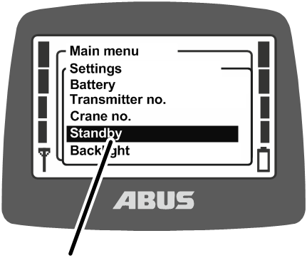
- Open the main menu with the MENU button.
- Open the “Settings” menu.
- Enter the code for the “Settings” menu.
See “Entering the code or PIN”.
The code for the menu is “0005”.
- Open menu item “Standby”.
Setting standby
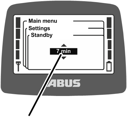
- The display shows the currently set time until the transmitter switches to the operating mode “Standby”.
- Set the required value.
If “Off” is selected here, the operating mode “Standby” is switched off.
The value “Off” is sorted in the list in front of the value “1 min” and can be reached by scrolling multiple times.
- Confirm the input with ENTER.
Displaying the remaining battery time and setting the alarm
The time remaining until the batteries are discharged is displayed here. Furthermore, the amount of battery time remaining before an alarm is displayed can be selected here.
Opening the menu item “Battery”
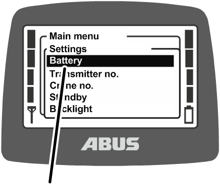
- Open the main menu with the MENU button.
- Open the “Settings” menu.
- Enter the code for the “Settings” menu.
See “Entering the code or PIN”.
The code for the menu is “0005”.
- Open the menu item “Battery”.
Displaying and setting the remaining time
Remaining time
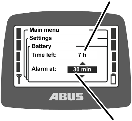
- The estimated battery time remaining is shown on the display.
- The alarm currently set for the battery time appears on the display.
- Select whether the alarm should be displayed for 10 minutes, 20 minutes or 30 minutes of remaining battery time.
- Confirm the input with ENTER.
Setting the display light
Here you select when the display light should light up and how long it should remain illuminated.
Opening the menu item “Backlight”
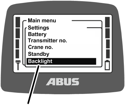
- Open the main menu with the MENU button.
- Open the “Settings” menu.
- Enter the code for the “Settings” menu.
See “Entering the code or PIN”.
The code for the menu is “0005”.
- Open the menu item “Backlight”
Setting the display light
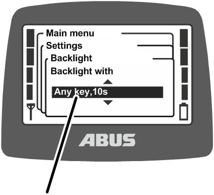
- The setting which has been selected for the display light appears in the display.
- Select when the display light should light up and how long it should remain illuminated.
The less time the display remains lit, the longer the operating time from one battery charge.
- “Backlight with any key, 5s”: The display lights up when any button or joystick is pressed and remains lit for 5 seconds after it is released.
- “Backlight with any key, 10s”: The display lights up when any button or joystick is pressed and remains lit for 10 seconds after it is released.
- “Backlight with Horn key, 5s”: The display lights up only when HORN is pressed and remains lit for 5 seconds after it is released.
- “Backlight with Horn key, 10s”: The display lights up only when HORN is pressed and remains lit for 10 seconds after it is released.
- “Backlight with any menu key, 5s”: The display lights up when MENU, ENTER or an arrow button/direct access button is pressed and remains lit for 5 seconds after it is released.
- “Backlight with any menu key, 10s”: The display lights up when MENU, ENTER or an arrow button/direct access button is pressed and remains lit for 10 seconds after it is released.
- Confirm using ENTER.
Setting light sensors
The brightness level of the surroundings at which the display light is to switch on is set here.
Opening the menu item “Light sensor”
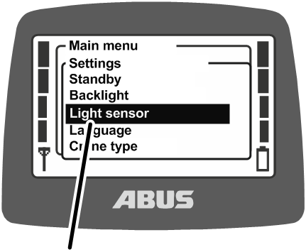
- Open the main menu with the MENU button.
- Open the “Settings” menu.
- Enter the code for the “Settings” menu.
See “Entering the code or PIN”.
The code for the menu is “0005”.
- Open the menu item “Light sensor”.
Setting light sensors
Current brightness
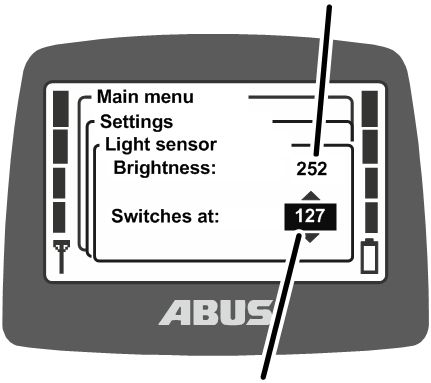
- The display shows the current brightness of the surroundings.
- Below this you set the brightness level at which the display light is to switch on.
The less time the display remains lit, the longer the operating time from one battery charge.
- The smaller the displayed value, the brighter are the surroundings currently. The larger the displayed value, the darker are the surroundings currently.
- If the measured brightness during running operation is greater than the set threshold, the display light switches on as previously set (5s or 10s, horn button or menu buttons). If the measured brightness during running operation is less than the set threshold, the display light does not switch on.
- Either: Set a high value as the threshold so that the display light is only switched on if the surroundings are very dark.
Or:
Set a low value as the threshold so that the display light switches on independently of the surroundings.
- Confirm using ENTER.
Setting the transmitter no. and crane no.
The transmitter no. and crane no. are set here. These numbers are used to help the crane operator uniquely identify and assign the crane and transmitter.
Transmitter no. and crane no. are displayed in “Standby” operating mode and the crane no. is displayed in “Normal” operating mode in the top right corner.
Transmitter no. and crane no. can be attached to the crane and transmitter by means of adhesive labels. Special adhesive labels can be obtained from ABUS. See “ABUS Service”.
Opening the menu item “Transmitter no.”
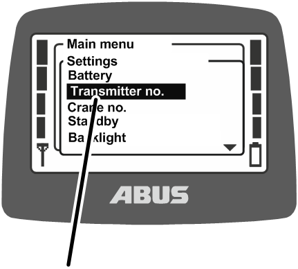
- Open the main menu with the MENU button.
- Open the “Settings” menu.
- Enter the code for the “Settings” menu.
See “Entering the code or PIN”.
The code for the menu is “0005”.
- Open the “Transmitter no.” menu item.
Setting the transmitter no.
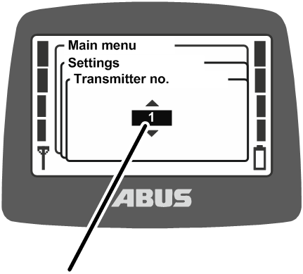
- The display shows the current transmitter no.
- Set the required transmitter no.
- Confirm using ENTER.
- The transmitter no. is saved.
Opening the menu item “Crane no.”
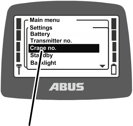
- Open the main menu with the MENU button.
- Open the “Settings” menu.
- Open the “Crane no.” menu item.
The menu item can only be opened with the transmitter logged in.
Setting the crane no.
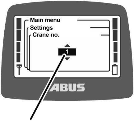
- The display shows the current crane no.
- Set the required crane no.
- Confirm using ENTER.
- The crane no. is saved.
- The message “Receiver: number has been changed” is displayed.
- Confirm using ENTER.
- Log out the transmitter and then log it back in.
Setting the language
The language used for the display and the messages is selected here.
Opening the menu item “Language”
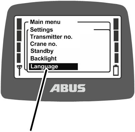
- Open the main menu with the MENU button.
- Open the “Settings” menu.
- Enter the code for the “Settings” menu.
See “Entering the code or PIN”.
The code for the menu is “0005”.
- Open the menu item “Language”.
Setting the language
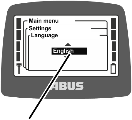
- The set language appears on the display.
- Select the required language.
- Confirm using ENTER.
Setting the crane type for display symbols
The crane type for the display symbols is set here. During operation of the crane in “Normal” operating mode, symbols for the direction of crane, trolley and load hook are displayed.
If the transmitter is used on a jib crane, the displayed symbols can be changed so that the symbols for slewing left and right are shown instead of the symbols for crane travel forward and back.
Opening the menu item “Crane type”
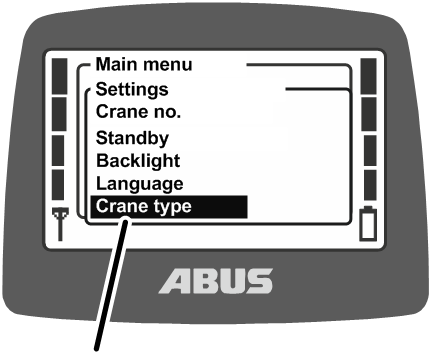
- Open the main menu with the MENU button.
- Open the “Settings” menu.
- Enter the code for the “Settings” menu.
See “Entering the code or PIN”.
The code for the menu is “0005”.
- Open the menu item “Crane type”.
Setting the crane type
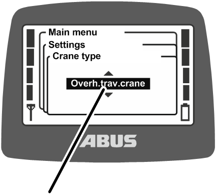
- The selected crane type is shown on the display.
- Select the required crane type (overhead travelling crane or jib crane).
- Confirm using ENTER.
Setting the direct access buttons
The four arrow buttons under the display can be allocated functions as direct access buttons in “Normal” operating mode (e.g. tare, super-precision lifting, etc.).
These functions can then either be opened using the corresponding menu items in the “Crane operation” menu on the transmitter, or they can be called up with one of the direct access buttons. Using the direct access buttons, the functions can be opened quickly and easily in “Normal” operating mode without having to open the menu beforehand. This is useful for the most frequently used functions.
Seldom-used functions are best operated using the menu to allow the direct access buttons to remain free for the most frequently used functions.
A number of functions can only be operated using the direct access buttons and cannot be opened using menu items in the menu.
The allocation of the four direct access buttons appears at the lower edge of the display.
Meaning of the symbols
- Symbol with black backlighting: The function is available and can be selected.
- Symbol with white backlighting: The function is currently unavailable.
- Symbol completely white: No function has been selected for this direct access button.
Available functions:
Symbol |
Description |
Function |
|---|---|---|
|
Zero with two arrows |
“Tare” |
|
Light bulb |
“Lighting” |
|
Hatched wall with arrow |
“Limit switch” |
|
Closed padlock |
“Log in” Crane is logged out. Press “Log in”. |
|
Open padlock |
“Log out” Crane is logged in. Press “Log out”. |
|
Closed double padlock |
“Tandem login” Crane is not logged in in tandem operation. Press “Tandem login”. |
|
Open double padlock |
“Tandem logout” Crane is logged in in tandem operation. Press “Tandem logout”. |
|
Ruler with detailed scale |
“Sup.pre.lift on” Super-precision lifting is switched off. Press to switch on. |
|
Ruler with coarse scale |
“Sup.pre.lift off” Super-precision lifting is switched on. Press to switch off. |
|
'T' with arrow |
“Teach-In” |
|
Line with two arrows |
Positioning assistance “Positioning” |
|
Flag |
Positioning control “Positioning” |
|
Suspended load at rest with two arrows |
“Sway control on” Sway control is switched off. Press to switch on. |
|
Swaying load |
“Sway control off” Sway control is switched on. Press to switch off. |
|
Play/Pause symbol |
“Travel release” |

Allocating direct access buttons
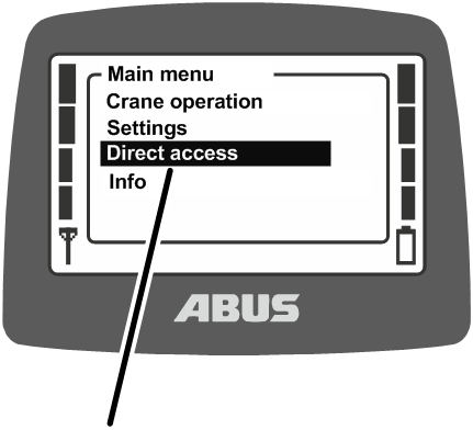
- Open the main menu with the MENU button.
- Open the “Direct access” menu.
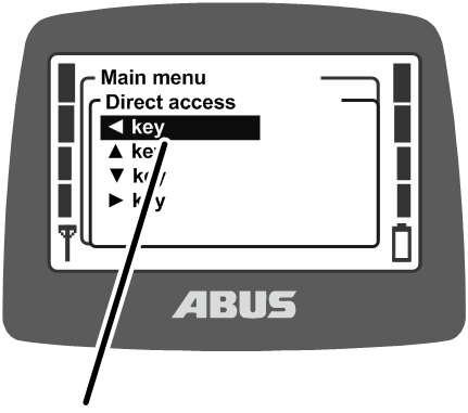
- Select the arrow button which is to be allocated a function.
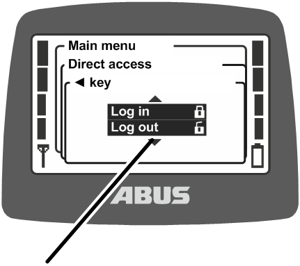
- Select the required function.
- Confirm using ENTER.
If this function was already allocated to another direct access button:
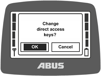
- The message “Change direct access keys?” appears on the display.
- Select the “OK” button and confirm.
- Quit the menu.
Function selected
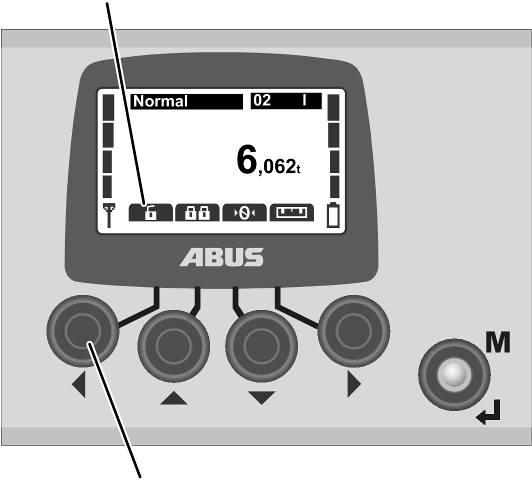
- The function is saved.
- The required function appears in the display in the ‘Normal’ operating mode above the direct access button selected.
Displaying transmitter information
An electronic type plate can be displayed in the main menu. This will show various information on ABURemote.
Opening the menu item “Info”
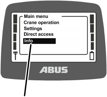
- Open the main menu with the MENU button.
- Open the menu item “Info”.
Displaying transmitter information
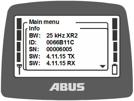
- Information on the transmitter appears in the display.
- FB:
433 MHz or 868 MHz
- BW:
Bandwidth of the radio channel (e.g. 25 kHz)
Wireless technology XR2
- ID: Set address of the receiver on the transmitter.
- SN: Serial no. of the transmitter
- SW: Software version Tx (transmitter)
- SW: Software version Rx (receiver)
- AP: Application Tx (transmitter)
- AP: Application Rx (receiver)
- Scroll through the information list with the UP and DOWN arrow buttons.
Setting the radio channel
This setting regulates whether the transmitter automatically searches for a free radio channel or transmits exclusively via a fixed radio channel.
If a fixed radio channel is set, the function “channel change” is disabled. The radio channel can then only be set using the function in the service menu described here.
Setting a fixed radio channel can be an advantage in order to avoid interference on other devices or by other devices. On the other hand, defining fixed radio channels could be a disadvantage in connection with other systems which have an automatic radio channel search function.
If the radio channel used by ABURemote is interfered with by other devices, this can lead to the connection being lost (e.g. fault 101).
A comprehensive frequency management plan should therefore be set up for the entire hall area.
- For this, create a list of all devices which operate with a radio transmission frequency in the 433 MHz range.
If the transmitter has an 868 MHz frequency range: Create a list of all devices which operate with a radio transmission frequency in the 868 MHz range.
- For all devices with manually adjustable radio channels, specify and set the respective devices according to the list. In doing so, allow as much bandwidth as possible between the channels.
Opening the menu item “Channel”
The menu item can be opened with the transmitter logged out or with it logged in.
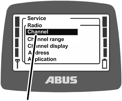
- Hold MENU depressed (5 seconds).
- The code query appears on the display.
- Enter the code for the service menu.
See “Entering the code or PIN”.
The code for the service menu is “0055”.
- Open the “Radio” menu.
- Open the menu item “Channel”.
Reading off and setting the radio channel
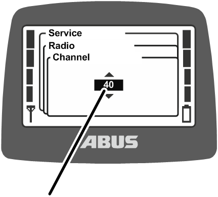
- The display shows the currently set value.
- Value between 1 and 69: The radio channel is permanently set to the corresponding value.
- Auto: The automatic search for a radio channel is activated.
- Set the radio channel required or “Auto”.
The value “Auto” is sorted in the list in front of radio channel 1 and can be reached by scrolling multiple times.
- Confirm the input with ENTER.
- The setting is automatically adopted by the receiver and does not need to be set separately there.
Channel and frequency assignment:
Radio channel |
Frequency (MHz) |
Radio channel |
Frequency (MHz) |
|---|---|---|---|
1 |
433,075 |
36 |
433,950 |
2 |
433,100 |
37 |
433,975 |
3 |
433,125 |
38 |
434,000 |
4 |
433,150 |
39 |
434,025 |
5 |
433,175 |
40 |
434,050 |
6 |
433,200 |
41 |
434,075 |
7 |
433,225 |
42 |
434,100 |
8 |
433,250 |
43 |
434,125 |
9 |
433,275 |
44 |
434,150 |
10 |
433,300 |
45 |
434,175 |
Radio channel |
Frequency (MHz) |
Radio channel |
Frequency (MHz) |
|---|---|---|---|
11 |
433,325 |
46 |
434,200 |
12 |
433,350 |
47 |
434,225 |
13 |
433,375 |
48 |
434,250 |
14 |
433,400 |
49 |
434,275 |
15 |
433,425 |
50 |
434,300 |
16 |
433,450 |
51 |
434,325 |
17 |
433,475 |
52 |
434,350 |
18 |
433,500 |
53 |
434,375 |
19 |
433,525 |
54 |
434,400 |
20 |
433,550 |
55 |
434,425 |
21 |
433,575 |
56 |
434,450 |
22 |
433,600 |
57 |
434,475 |
23 |
433,625 |
58 |
434,500 |
24 |
433,650 |
59 |
434,525 |
25 |
433,675 |
60 |
434,550 |
26 |
433,700 |
61 |
434,575 |
27 |
433,725 |
62 |
434,600 |
28 |
433,750 |
63 |
434,625 |
29 |
433,775 |
64 |
434,650 |
30 |
433,800 |
65 |
434,675 |
31 |
433,825 |
66 |
434,700 |
32 |
433,850 |
67 |
434,725 |
33 |
433,875 |
68 |
434,750 |
34 |
433,900 |
69 |
434,775 |
35 |
433,925 |
Only for 868 MHz radio channel
Radio channel |
Frequency (MHz) |
|---|---|
1 |
869,725 |
2 |
869,750 |
3 |
869,775 |
4 |
869,800 |
5 |
869,825 |
6 |
869,850 |
7 |
869,875 |
8 |
869,900 |
9 |
869,925 |
10 |
869,950 |
11 |
869,975 |
Setting the channel range
Whether the transmitter should use all radio channels (1 through 69) during the automatic search, or only the radio channels 40 through 69, is set here. This is important for the operation in certain countries with special regulations.
ABURemote generally operates with a duty cycle of 100% with regard to the transmission duration on a radio channel. The duty cycle determines how much time within a certain time interval ABURemote uses the radio channel or takes a break. A duty cycle of 100% means that ABURemote completely occupies the radio channel and transmits continuously.
In certain countries, only the radio channels 40 to 69 are permitted to be used with a duty cycle of 100%. In these countries the radio channels 1 to 39 must therefore be blocked for ABURemote and/or the transmission power reduced.
Opening menu item “Channel range”
The menu item can only be opened with the transmitter logged out.
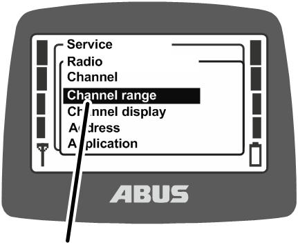
- Hold MENU depressed (5 seconds).
- The code query appears on the display.
- Enter the code for the service menu.
See “Entering the code or PIN”.
The code for the service menu is “0055”.
- Open the “Radio” menu.
- Open menu item “Channel range”.
Reading off and setting the channel range
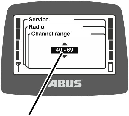
- The currently set channel range is shown on the display.
- 1 – 69: ABURemote uses all radio channels 1 to 69 in the automatic search for a radio channel and in the case of fixed settings. The radio channels are occupied with a 100% duty cycle.
- 40 – 69: ABURemote uses only radio channels 40 to 69 in the automatic search for a radio channel and in the case of fixed settings. The radio channels are occupied with a 100% duty cycle.
Setting the transmission power of transmitter and receiver
This setting defines whether the transmitter and the receiver should transmit at full transmission power or whether the transmission power should be reduced.
If several radio systems (radio remote control for cranes, but also other systems with wireless connection) are operated in close proximity to one another, the signals of one radio system (particularly if the radio partner is located at a great distance) can be overshadowed by the adjacent range of a different radio system (especially if the radio partner of the other radio system is located close to the ABURemote transmitter or receiver).
In these cases it may make sense to reduce the transmission power of individual systems or even of all systems. If multiple transmitters are operated in small spaces, it is usually useful to reduce the transmission power of all transmitters. Adapting the transmission power of receivers is only recommended in exceptional cases.
Opening the menu item “Transmission power”
The menu item “Transmitter” can be opened with the transmitter either logged out or logged in.
The menu item “Receiver” can only be opened with the transmitter logged in.
Menu item “Transmitter”
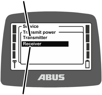
- Hold MENU depressed (5 seconds).
- The code query appears on the display.
- Enter the code for the service menu.
See “Entering the code or PIN”.
The code for the service menu is “0055”.
- Open the menu item “Transmission power”.
- Open the menu item “Transmitter” or “Receiver”.
Reading off and setting the transmission power
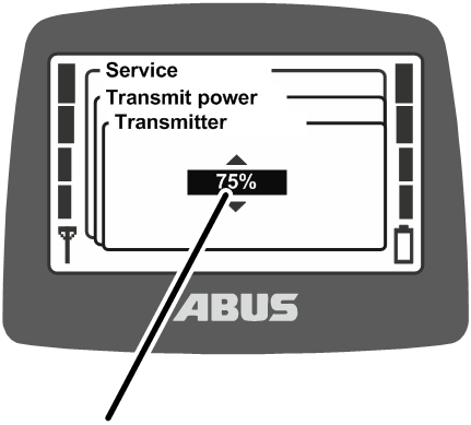
- The transmission power currently set on the transmitter or receiver is shown on the display.
- Set the required value.
The transmission power can be set to 200% (option) 100%, 75%, 50%, 25% and 12%.
- Confirm the input with ENTER.
Setting the channel display
Whether or not the current radio channel is to be shown on the display in “Normal” operating mode is set here.
This can be helpful if problems occur with the automatic selection of the radio channel.
If the channel display is switched on in “Normal” operating mode, the current radio channel is displayed at the bottom left instead of the antenna symbol.
Opening the menu item “Channel display”
The menu item can be opened with the transmitter logged out or with it logged in.
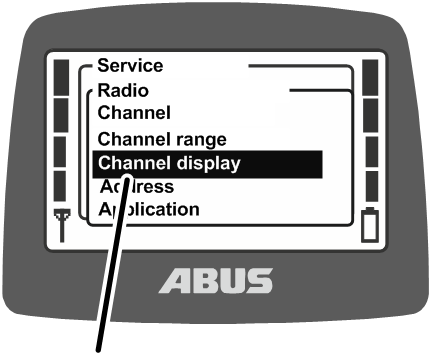
- Hold MENU depressed (5 seconds).
- The code query appears on the display.
- Enter the code for the service menu.
See “Entering the code or PIN”.
The code for the service menu is “0055”.
- Open the “Radio” menu.
- Open the menu item “Channel display”.
Switching channel display on and off
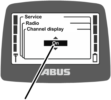
- The display indicates whether the “Channel display” is currently switched on or off.
- Switch the “Channel display” on or off.
- Confirm using ENTER.
Show operating hours of transmitter and receiver
This shows how long the transmitter and receiver have been in operation. The operating hours counter counts upwardly minute-by-minute and is saved when the crane/transmitter is switched off.
Opening the menu item “Operating hours”
The menu item “Transmitter” can be opened with the transmitter either logged out or logged in.
The menu item “Receiver” can only be opened with the transmitter logged in.
Menu item “Transmitter”
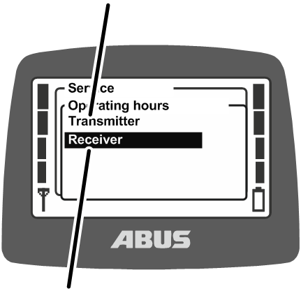
- Hold MENU depressed (5 seconds).
- The code query appears on the display.
- Enter the code for the service menu.
See “Entering the code or PIN”.
The code for the service menu is “0055”.
- Open the menu item “Operating hours”.
- Open the menu item “Transmitter” or “Receiver”.
Showing operating hours
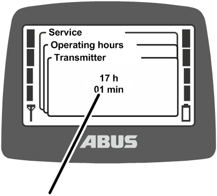
- The operating hours of the transmitter or receiver are shown on the display.
Setting the waiting time
How long the transmitter should wait after login and release before the crane can be controlled is set here.
The waiting time makes sense particularly with cranes with ABULiner frequency converter or with ABUControl.
The waiting time is shown in the form of a progress bar on the display and conveys to the crane operator that the control is currently being started up.
With ABUControl, the waiting time is fixedly specified via the PLC of the control.
Opening the menu item “Waiting time”
The menu item can only be opened with the transmitter logged in.
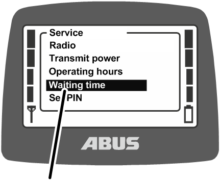
- Hold MENU depressed (5 seconds).
- The code query appears on the display.
- Enter the code for the service menu.
See “Entering the code or PIN”.
The code for the service menu is “0055”.
- Open the menu item “Waiting time”.
Setting and displaying the waiting time
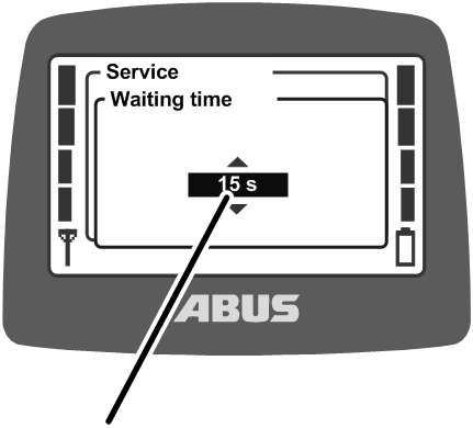
- The waiting time currently set is shown on the display.
- Set the required value.
The waiting time can be set in 5-second steps between 5 and 30 seconds, or switched off.
The value “Off” is sorted in the list in front of the value “5 s” and can be reached by scrolling multiple times.
- Confirm using ENTER.
Setting PIN for transmitter PIN code and protected functions
The transmitter PIN code protects the transmitter so that only authorised persons can use it.
Furthermore, the “Override limit switch” and “Switch off load limiting system” functions can also be protected by a PIN so that only authorised persons can use them.
The menu item “Set PIN” is used to activate the various PIN levels of the transmitter and set the various PINs.
Overview of the PIN levels:
Level 0: Transmitter PIN code
- If PIN level 0 is activated on the transmitter, the transmitter can only be switched on if the corresponding correct PIN is entered when switching on the transmitter.
When switching on or logging in the transmitter, the PIN prompt appears if any of the PIN level in the transmitter are activated. If the PIN for PIN level 0 is entered, the transmitter can then be switched on or logged in.
Pin level 0 is only saved in the transmitter. This means that the corresponding PIN prompt appears no matter which receiver the transmitter is logged into.
Level 1: Override limit switch
- On the receiver, the “Override limit switch” function is protected by a PIN. The limit switch can only be overridden if PIN level 1 is additionally activated on the transmitter and the corresponding correct PIN has been entered during switching on or logging in the transmitter. PIN level 1 automatically also contains PIN level 0.
When switching on or logging in the transmitter, the PIN prompt only appears if one of the PIN levels in the transmitter is activated. If the PIN for PIN level 0 is entered, the transmitter can be logged in, but the protected function “Override limit switch” will remain locked. If the PIN for PIN level 1 is entered at the PIN prompt, the transmitter can be logged in and the direct access button “Override limit switch” can be pressed.
Depending on the version of the transmitter, the protected function “Override limit switch” can also be switched on and off using a key switch. See “Operating additional functions on the crane using key switches”. It is then necessary to activate a PIN level of the transmitter. If a PIN level of the transmitter is activated parallel to a key switch, the protected functions can equally be unlocked by key switch and PIN.
Level 2: Switching off the load limiting system.
- On the receiver, the function “Switch off load limiting system” is protected by a PIN. The load limiting system can only be switched off if PIN level 2 is additionally activated on the transmitter and the corresponding correct PIN has been entered during switching on or logging in of the transmitter. PIN level 2 automatically also contains PIN level 0.
When switching on or logging in the transmitter, the PIN prompt only appears if one of the PIN levels in the transmitter is activated. If the PIN for PIN level 0 is entered, the transmitter can be switched on, but the load limiting system remains switched on and the crane can be operated with reduced maximum load capacity. If the PIN for PIN level 2 is entered at the PIN prompt, the load limiting system is switched off and the crane can lift with maximum load capacity.
Depending on the version of the transmitter, the protected load limiting system can also be switched on and off using a key switch. See “Operating additional functions on the crane using key switches”. It is then necessary to activate a PIN level of the transmitter. If a PIN level of the transmitter is activated parallel to a key switch, the protected functions can equally be unlocked by key switch and PIN.
Level 3: Combination of level 1 and level 2.
- On the receiver, the “Override limit switch” and “Switch off load limiting system” functions are protected by a PIN. The limit switch can only be overridden and the load limiting system can only be switched off if PIN level 3 is additionally activated on the transmitter and the corresponding correct PIN has been entered during switching on or logging in of the transmitter. PIN level 3 automatically also contains PIN levels 0, 1 and 2.
When switching on or logging in the transmitter, the PIN prompt only appears if one of the PIN levels in the transmitter is activated. If the PIN for PIN level 0 is entered, the transmitter can be logged in. If the PIN for PIN level 3 is entered, the transmitter can be logged in, the direct access button “Override limit switch” can be pressed, and lifting can be performed with the maximum load capacity.
The protected functions in the receiver are configured and administered at the factory.
Thus, the functions are protected no matter which transmitter is logged into the receiver (e.g. in the case of a replacement transmitter). However, the PIN required for unlocking is saved in the transmitter, and can thus be set specifically for the transmitter in question.
The protected functions can only be operated if the respective PIN level has been configured in the receiver at the factory and the same PIN level is activated on the transmitter. If the correct PIN for the PIN level is then entered when switching on or logging in the transmitter, unlocking is possible. The configuration in the receiver cannot be adapted. For the transmitter, the PIN levels can be activated in the “Settings” menu.
If a crane with protected functions in the receiver is operated with a transmitter without activated PIN levels or without a key switch, the protected functions cannot be unlocked.
PIN level 0 is however saved in the transmitter. This means that the PIN is prompted on this transmitter no matter which receiver the transmitter is logged into. Conversely, the crane can be operated without entry of a PIN if a transmitter with no activated PIN levels is connected to the receiver.
Note regarding safety:
The menu item “Set PIN” is accessible in the service menu, which can be opened with the service menu code “0055”. The menu item has no further protections. This means that the PINs for the PIN levels cannot be accidentally changed since they lie in the protected service menu, however there is no absolute protection against misuse, deactivation of the PIN levels or changing of the PIN.
Opening the menu item “Set PIN”
The menu item can be opened with the transmitter logged out or with it logged in.
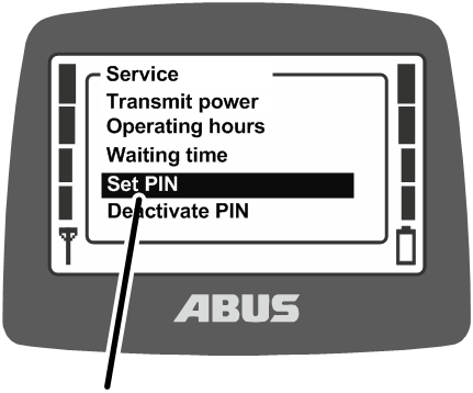
- Hold MENU depressed (5 seconds).
- The code query appears on the display.
- Enter the code for the service menu.
See “Entering the code or PIN”.
The code for the service menu is “0055”.
- Open the menu item “Set PIN”.
Activating PIN levels and setting the PIN
Specified PIN
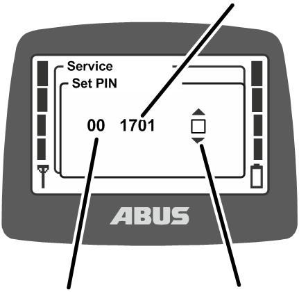
- The display shows the first PIN level 0.
- Activate PIN level 0 to switch on the transmitter PIN code.
Activate PIN level 1 to protect the function “Override limit switch” with a PIN.
Activate PIN level 2 to protect the function “Switch off load limiting system” with a PIN.
Activate PIN level 3 to protect the functions “Override limit switch” and “Switch off load limiting system” with a PIN.
- Specified PIN: The PIN which is valid for the respective PIN level is displayed and specified here.
- Status: Whether the PIN level is activated (black box) or whether the PIN level is deactivated (white box) is displayed and specified here.
- Select the PIN level to be edited using the UP and DOWN arrow buttons.
- The PIN and the status of the respective PIN level are displayed.
- Select the digits to be set for the PIN using the LEFT and RIGHT arrow buttons.
- Set the digits using the UP and DOWN arrow buttons.
- Select the box for activating or deactivating the PIN level using the RIGHT and LEFT arrow buttons.
- Activate (black box) or deactivate (white box) the PIN level using the UP and DOWN arrow buttons.
- Press ENTER.
- All PINs are saved.
Switching off all PIN levels
All PIN levels can be switched off simultaneously here.
If PIN levels are deactivated, they are only deactivated in the transmitter. The factory configuration of the receiver is not affected by this. This means that the protected functions (“Override limit switch” and “Switch off load limiting system”) are then unavailable.
Only Pin level 0 is completely deactivated by this, since it is only saved in the transmitter. The transmitter can afterwards be switched on or logged in without having to enter a PIN.
Opening the menu item “Deactivate PIN”
The menu item can be opened with the transmitter logged out or with it logged in.
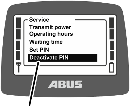
- Hold MENU depressed (5 seconds).
- The code query appears on the display.
- Enter the code for the service menu.
See “Entering the code or PIN”.
The code for the service menu is “0055”.
- Open the menu item “Deactivate PIN”.
Switching off PIN levels
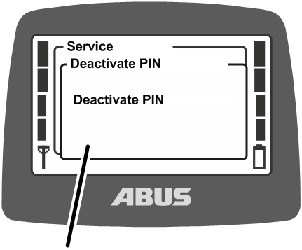
- The display shows the “Deactivate PIN” prompt.
- Confirm using ENTER.
Selection mode for setting the trolley selection and crane selection
Whether the trolley selection and crane selection are set with the flip switch “Direct” or “Safe” is set here.
In direct trolley and crane selection, the flip switch is pressed to switch between trolleys and cranes.
In safe trolley and crane selection, first the flip switch is pressed and held and then ENTER is additionally pressed to switch between trolleys and cranes.
This prevents unintentional switching between trolleys or cranes (e.g. due to a glove catching on the switch).
Opening the menu item “Selection mode”
The menu item can be opened with the transmitter logged out or with it logged in.
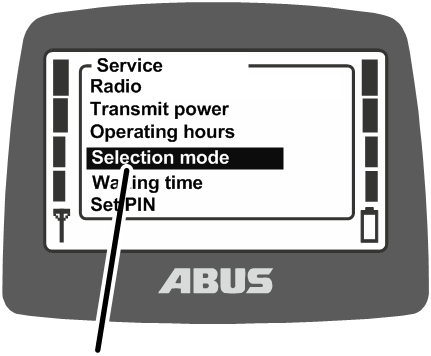
- Hold MENU depressed (5 seconds).
- The code query appears on the display.
- Enter the code for the service menu.
See “Entering the code or PIN”.
The code for the service menu is “0055”.
- Open the menu item “Selection mode”.
Displaying and setting the selection mode
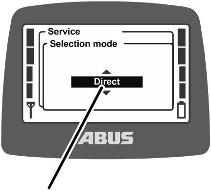
- The setting which is currently set is shown on the display.
- Set the required value:
With “Direct”, the crane operator can change between cranes and trolleys directly using the flip switches.
With “Safe”, the crane operator can change between cranes and trolleys by pressing and holding the flip switches and then pressing ENTER.
- Confirm using ENTER.
To operate a crane with two trolleys, see “Operating a crane with two trolleys”.
To operate two trolleys in tandem operation, see “Operating cranes in tandem operation”.
Setting the address (linking transmitter to a receiver)
The address of the receiver in the transmitter is set here. Transmitter and receiver must be set to the same address so that they can communicate with each other.
The address in the receiver is fixed and cannot be changed. In the transmitter, the address of the receiver to which the transmitter is to be connected can be set in the service menu. The receiver address can be found on the type plate.
In other words, the address defines which transmitter can communicate with which receiver. Transmitters and receivers can only communicate with one another when the address of the receiver is set in the transmitter.
Opening the menu item “Address”
The menu item can only be opened with the transmitter logged out.
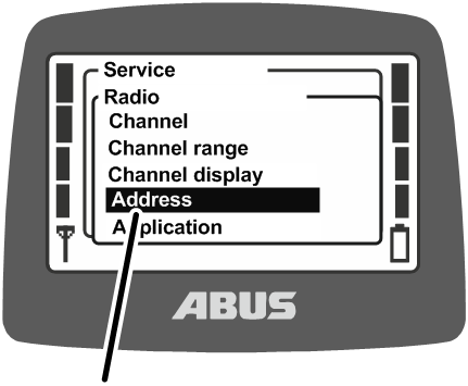
- Hold MENU depressed (5 seconds).
- The code query appears on the display.
- Enter the code for the service menu.
See “Entering the code or PIN”.
The code for the service menu is “0055”.
- Open the “Radio” menu.
- Open the menu item “Address”.
Displaying and setting the address
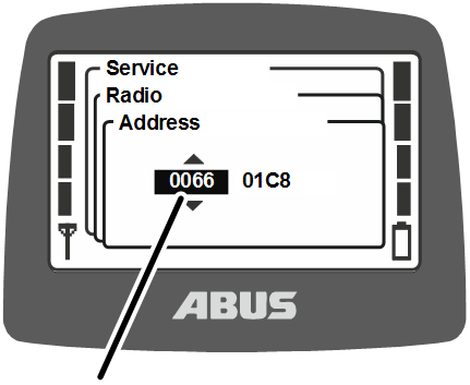
- The address currently set is shown on the display.
- Set the new address.
The address can be entered in several blocks. The address consists of eight characters.
- Confirm the input with ENTER.
- Switch the transmitter off, remove the rechargeable batteries briefly and then reinsert them, switch the transmitter back on again.
Note:
The setting in this menu can only be made for transmitters with no current entries in their multi-user list. For transmitters with the multi-user function, users are automatically forwarded to a multi-user list.
See “Creating/amending multi-user list”.
Putting the replacement transmitter into operation
A replacement transmitter is delivered for one or several cranes and can be used if the original transmitter is defective.
In order to put a replacement transmitter into operation, the receiver address of the faulty transmitter must be entered in the replacement transmitter.
The transmitter must be logged out before the replacement transmitter can be put into operation.
- Log out the defective transmitter from the receiver.
- Log out the transmitter either per menu or direct access button. See “Logging out and switching off the transmitter”.
- Or, if the transmitter is no longer available for example, switch off the crane and then switch it back on again. This switches off the receiver and the transmitter is automatically logged out.
- Find out the address that was set on the defective transmitter.
- Read off the address in the menu item “Info” on the defective transmitter. See “Displaying transmitter information”.
- Or, if the transmitter is no longer is available for example, read off the address from the type plate of the receiver.
- Set the same address on the replacement transmitter that was set on the defective transmitter. See “Setting the address (linking transmitter to a receiver)”.
- Switch the transmitter off, remove the rechargeable batteries briefly and then reinsert them, switch the transmitter back on again.
- The replacement transmitter can now be used.
Setting the application of the transmitter
The application of the transmitter is set here. The application is a number which represents the model and specific version of transmitters. The set application must match the model of the transmitter while also matching the connected receiver.
The application defines these variants:
- Model of the transmitter (ABURemote Button or Joystick)
- Transmitter version (standard transmitter or transmitter with three joysticks)
- Versions of the joystick (two-stage or proportional joystick)
- Model of the receiver (receiver with relay or CAN bus receiver)
Sometimes it can be necessary to change the application of the transmitter, for example, if a transmitter that has previously been used with a receiver with relay is then to be used on a crane with CAN bus receiver.
The application currently set is shown in the menu item “Info”. See “Displaying transmitter information”.
Opening the menu item “Application”
The menu item can only be opened with the transmitter logged out.
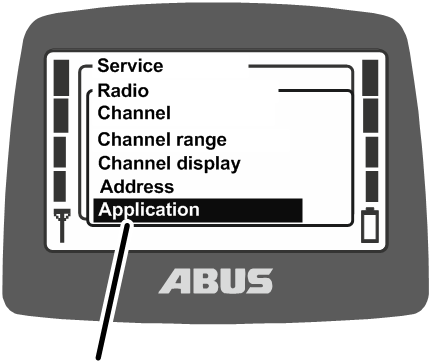
- Hold MENU depressed (5 seconds).
- The code query appears on the display.
- Enter the code for the service menu.
See “Entering the code or PIN”.
The code for the service menu is “0055”.
- Open the “Radio” menu.
- Open the menu item “Application”.
Setting the application
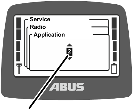
- The “Application” currently set is shown on the display.
- Set “Application”.
Applications for receivers with relay:
Transmitter |
Application Wireless technology XR2 |
|---|---|
ABURemote Button |
31 |
ABURemote Joystick with two joysticks, two-stage |
31 |
ABURemote Joystick with two joysticks, proportional |
32 |
ABURemote Joystick with three joysticks, two-stage |
31 |
ABURemote Joystick with three joysticks, proportional |
32 |
ABURemote Joystick with three joysticks, two-stage with inverted travel direction |
35 |
ABURemote Joystick with three joysticks, proportional with inverted travel direction |
36 |
Applications for CAN bus receivers:
Transmitter |
Application Wireless technology XR2 |
|---|---|
ABURemote Button |
31 |
ABURemote Joystick with two joysticks, two-stage |
31 |
ABURemote Joystick with three joysticks, two-stage |
33 |
ABURemote Joystick with two joysticks, proportional |
32 |
ABURemote Joystick with three joysticks, proportional |
34 |
ABURemote Joystick with 2 trolleys and 3 joysticks, two-stage for inverted travel direction |
37 |
ABURemote Joystick with 2 trolleys and 3 joysticks, proportional for inverted travel direction |
38 |
- Confirm using ENTER.
Opening and closing the receiver
In the case of repairs or replacement, the receiver must be opened.
Opening the housing
Upper clip fastenersCover
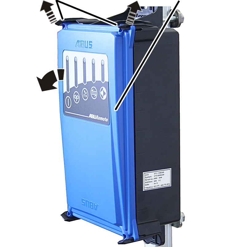
- Remove the semi-round head screws (4x) from the cover.
- Lightly push the two clip fasteners at the top outwards.
- At the same time, pull the upper part of the cover away from the housing.
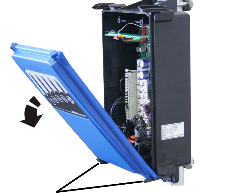
- Tilt the cover downwards until it is almost horizontal.
- The cover will be automatically released from the lower clip fasteners when it is tilted.
- Put the cover aside.
Closing the receiver
Clip fasteners
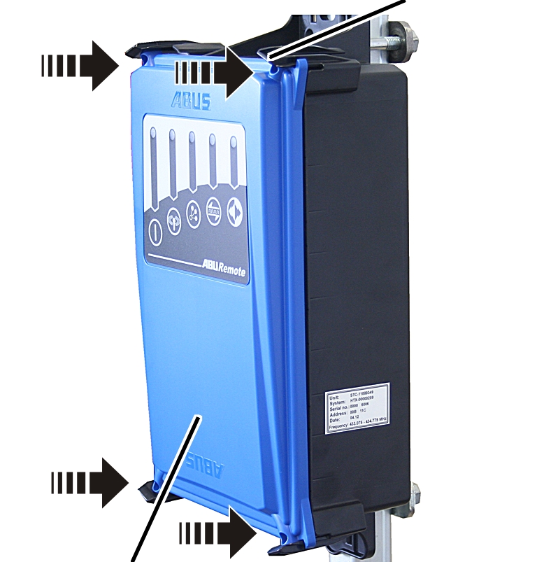
- Place all four corners of the cover onto the housing.
- Clip the cover into all four clip fasteners at the same time.
- Screw the cover into place using semi-round M3.5x14 head screws. 0.5 Nm.
Replacing the receiver
If the receiver is defective, it must be replaced. If the receiver needs to be replaced, the connection cable can be disconnected from the receiver. This ensures a new cable does not have to be laid from the panel to the receiver.
In the case of repairs or replacement, the receiver must be opened.
Removing the old receiver
- Open the cover. See “Opening the housing”.
- Pull the cable bushing for the connection cable out of the housing.
- Detach the connection cable coupler plugs from the receiver.
- Undo the threaded bracket on the receiver and pull off the receiver.
Installing a new receiver
Threaded bracketPlate
- Hold the receiver on the square tube.
- Insert one threaded bracket each through the top and bottom of the housing.
- Insert one plate onto each threaded bracket from the rear side.
- Tighten the threaded bracket with the rib nuts M8 (2 x per threaded bracket). 15 Nm.
Connecting the receiver
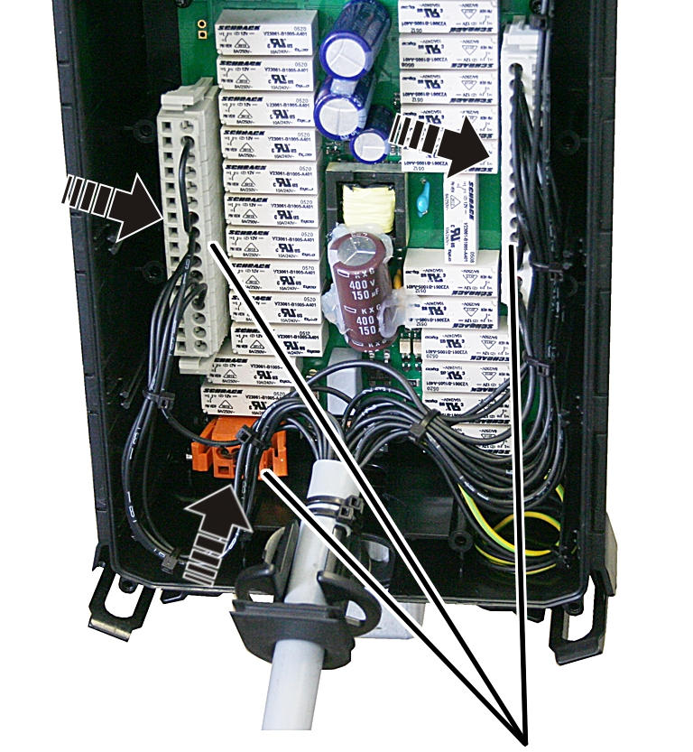
- Insert the coupler plugs for the connection cable on the pin multipoint connector on the circuit board.
The coupler plugs and the pin multipoint connectors have coding pins. This ensures the coupler plugs cannot be interchanged.
Cable bushing (as strain relief)
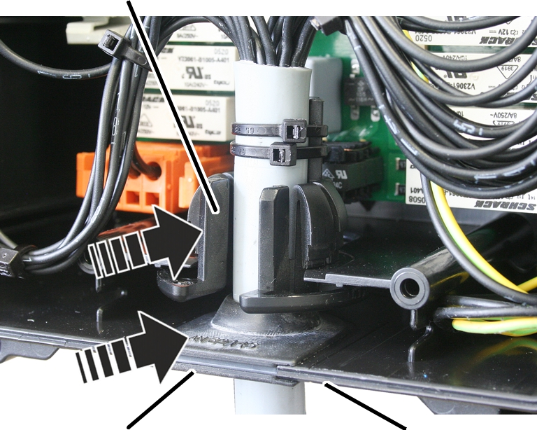
- Push the connection cable with the two cable bushings into the housing.
Insert the rubber lips of the cable bushing (seal) so that they lay flat against the housing both inside and outside.
Insert the cable bushing (strain relief) into the housing as shown in the figure.
- Close the cover. See “Closing the receiver”.
Setting the address on the transmitter
To put a replacement receiver into operation, the address of the new receiver must be set on the transmitter(s) which are to control the crane with the new receiver.
- Read off the address of the replacement receiver on the receiver’s type plate.
- Set the address on the transmitter. See “Setting the address (linking transmitter to a receiver)”.
- Switch the transmitter off, remove the rechargeable batteries briefly and then reinsert them, switch the transmitter back on again.
Welding on the crane
When performing any welding work on the crane, detach the connection cable from the receiver and remove the receiver!
When performing welding work on the crane, the receiver could sustain damage due to the high voltages produced by the welding equipment.
Detach the connection cable from the receiver.
Setting and selecting multi-user
ABURemote can be used in multi-user mode (option). This allows a transmitter to be logged into different cranes. In turn, an operating plan can be created for multiple cranes. A crane can be controlled by multiple transmitters and a transmitter can control multiple cranes. In this way, for example, a transmitter can be used as a replacement transmitter when the actual transmitter is defective.
The required crane can be selected during the login process from a selection list using its crane number.
Setting the transmitter no. and crane no.
The transmitter no. and crane no. are set here. These numbers are used to uniquely identify and assign the crane and transmitter.
Transmitter no. and crane no. are displayed in “Standby” operating mode and the crane no. is displayed in “Normal” operating mode in the top right corner. Additionally, on transmitters with multi-user function, the crane no. is used during login for selecting the required crane.
- Transmitter no. and crane no. are displayed in “Standby” operating mode
- In the “Normal” operating mode the crane number is displayed in the top right corner and used during multi-user login for selecting the required crane.
- Transmitter no. and crane no. can be attached to the crane and transmitter by means of adhesive labels. Special adhesive labels can be obtained from ABUS. See “ABUS Service”.
However, note that a specific assignment using transmitter numbers and crane numbers is no longer possible as the multi-user function can be linked to different cranes. Cranes are selected using the menu in the transmitter.
Open the menu item “Transmitter no.”:
- Open the main menu with the MENU button.
- Open the “Settings” menu.
- Enter the code for the “Settings” menu.
The code for the menu is “0005”.
- Open the “Transmitter no.” menu item.
Set transmitter no.:
- The display shows the current transmitter no.
- Set the required transmitter no. using the arrow buttons.
- Confirm using ENTER.
- The transmitter no. is saved.
Open the menu item “Crane no.”:
- Open the main menu with the MENU button.
- Open the “Settings” menu.
- Open the “Crane no.” menu item.
The menu item can only be opened with the transmitter logged in.
Set the crane no.:
- The display shows the current crane no.
- Set the required crane no. using the arrow buttons.
- Confirm using ENTER.
- The crane no. is saved.
- Confirm using ENTER.
- Log out the transmitter and then log it back in.
- The message “Receiver: number has been changed” is displayed.
Creating/amending multi-user list
To be able to log the transmitter in on different receivers, a list of receivers which the transmitter can log into must be created in the transmitter. The list must be created on all receivers so multi-user mode can be used.
If a multi-user list has been created, users are automatically forwarded from the menu item “Address” to the menu item “Multi-user”. The menu item “Address” is deactivated.
- Hold MENU depressed (5 seconds).
- The code query appears on the display.
- Enter the code for the service menu.
The code for the service menu is “0055”.
- Select menu item “Multi-user”.
The menu item can only be opened with the transmitter logged out.
Crane no.Address
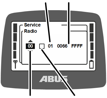
- A row in the multi-user list appears on the display.
- Row: The multi-user list is displayed row-by-row in the window. This is the number of the row currently displayed in the list. The first row has the number ‘00’.
- Activity: Rows can be activated (filled in square) and deactivated (empty square) using “Activity”.
- Crane no.: Here the crane number is shown for the row currently displayed. The crane number is later used in the login process to select on which crane the transmitter is to be logged in.
- Address: The address of the recipient on which the transmitter is to be logged in is displayed here.
- Set the cursor to the row value using the RIGHT/LEFT arrow buttons.
- Select the row to be edited using the UP/DOWN arrow buttons.
- The crane number and the address of the corresponding rows in the multi-user list are displayed.
If there is no entry in the selected line, “‑ ‑” is displayed instead of a crane number.
- Set the cursor to the crane no. value using the RIGHT/LEFT arrow buttons.
- Set the crane number using the UP/DOWN arrow buttons.
The crane number set here is displayed in the crane list upon login and helps the crane operator to select the required crane.
The crane number should be identical to the crane number saved in the corresponding receiver. If the crane no. entered here in the multi-user list is not identical to the crane number set in the receiver, the crane number in the multi-user list will be automatically overwritten at the first login.
The crane number can therefore not be changed here. To change the crane number, see “Setting the transmitter no. and crane no.”.
- Set the cursor to the address value using the RIGHT/LEFT arrow buttons.
- Set the address using the UP/DOWN arrow buttons.
The address set here is crucial for the radio connection between transmitter and receiver. The transmitter will later be logged in to the receiver address set here, during the log in process. The appropriate address can be found on the type plate of the appropriate receiver.
- Confirm using ENTER.
- The multi-user list is saved.
Logging in the transmitter
In some situations, the transmitter does not automatically log back in to the receiver:
- The transmitter was not logged in at the time of being switched off.
- The crane is not within range of the transmitter.
- The crane was switched off in the meantime.
- Another transmitter is logged in to the crane.
- The transmitter was manually logged out beforehand.
- An automatic login was previously cancelled.
If the transmitter does not log back in automatically:
- Either:
Press the direct access button “Log in” (closed padlock).
Or:
Open the main menu with the MENU button,
open the menu “Crane operation”,
open the menu item “Log in”.
- If the transmitter or a function is protected by a PIN: The window “Enter PIN” appears on the display.
- Enter PIN. See “Entering the code or PIN”.
When the multi-user function is activated on the transmitter (more than one address has been entered into the multi-user list):
When the multi-user function is activated on the transmitter, a list with crane numbers appears. The transmitter can be logged in on the displayed crane number.
Crane nos.
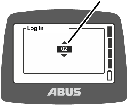
- A list with crane numbers appears.
The transmitter can be logged in on the crane displayed here.
- Using the arrow buttons, select the required crane number to which the transmitter should be logged in.
To ensure clarity when selecting cranes, make sure to set sensible crane numbers to mark the crane appropriately.
- Press ENTER.
- The transmitter logs in to the receiver.
- The display shows “Release”.
- Press the HORN flip switch and let it go.
- The sound of the horn can be heard at the crane.
- The crane is ready for use.
- Compare the crane number shown in the display with the crane number required.
Logging out the transmitter
For another transmitter to be logged in on the crane, the transmitter last logged in on the crane must be logged out manually.
Note:
If a transmitter has been logged in on a crane, this crane is locked for all other transmitters even if the connected transmitter switches to standby mode or is switched off. For another transmitter to be logged in on the crane, either the last connected transmitter must be logged out manually or the crane must be restarted.
- Either:
Press the direct access button “Log out” (opened padlock).
Or:
Open the main menu with the MENU button,
open the menu “Crane operation”,
open the menu item “Log out”.
- The transmitter logs out at the crane and reverts to the “Not logged in” operating mode.
- The transmitter can now be logged in on another crane or another transmitter can be logged in on this crane.
- With tandem control system: Another transmitter can now operate the crane in tandem operation.
Eliminating faults on the ABURemote
If the crane does not function with ABURemote, or does not function as expected, a fault in the ABURemote may be the cause.
Resetting after a malfunction
Depending on the fault, the transmitters and receivers have to be reset differently.
In the event of transmitter faults:
- A message appears on the display.
- Confirm using the “OK” button.
In the event of severe transmitter faults:
- A message appears on the display.
There is no button available.
- Switch off the transmitter using the stop button, switch it on again and log in.
If the fault persists: Contact ABUS Service. See “ABUS Service”.
In the event of receiver faults:
- A message appears on the display which begins with “Receiver”.
- Switch off the crane at the mains switch.
- Wait at least 60 seconds.
- Message 101 “Receiver disconnected” appears on the display.
- Switch on the crane at the mains switch.
- Log in the transmitter.
If the fault persists: Contact ABUS Service. See “ABUS Service”.
ABURemote fault codes
In the event of ABURemote faults:
Fault code
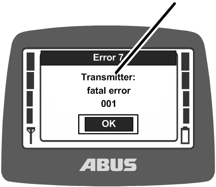
- A message with the fault code appears on the display.
In the event of LIS-SV faults:
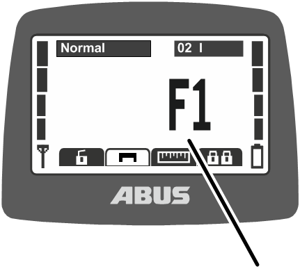
- The fault from the LIS-SV appears on the display in the same place as where the load is usually shown.
See product manual “LIS-SV load indicator system”.
Code |
Fault |
Possible cause |
Eliminating the fault |
|---|---|---|---|
The transmitter cannot be switched on. |
Batteries are discharged. |
Charge the batteries. See “Charging the batteries”. |
|
No batteries inserted. |
Insert charged batteries. See “Inserting rechargeable batteries”. |
||
Stop button defective. |
Contact ABUS Service. See “ABUS Service”. |
||
The transmitter does not log in (no message appears on the display) |
Exit the transmitter/receiver range. |
Reenter the transmitter/receiver range and log in again. |
|
The receiver was switched off. |
Switch the receiver on again. |
||
Radio interference |
Identify and eliminate the cause of the interference. |
||
Change the radio channel. See “Changing the radio channel”. |
|||
Another transmitter is logged in to the crane in tandem operation. |
Log the other transmitter out from tandem operation. See “Operating cranes in tandem operation”. |
||
207 208 209 210 |
“Receiver: emergency stop relays faulty” |
The relay for the emergency stop function is faulty. |
Switch the crane off and back on again. If the fault appears again, contact ABUS Service. See “ABUS Service”. |
The relay for the emergency stop function does not switch on although the receiver switches the signal (e.g. because the hoist limit switch has been activated on the hoist). |
Eliminate the cause for the main contactor of the crane switching off. |
||
105 |
“At start-up do not activate any button” |
A joystick or a flip switch was pressed when switching on. |
Press ENTER, let go of all joysticks and flip switches, and switch on again. |
Joystick or flip switch defective. |
Contact ABUS Service. See “ABUS Service”. |
||
101 |
“Receiver disconnected” |
The receiver was switched off. |
Switch the receiver on again. |
Radio interference |
Identify and eliminate the cause of the interference. |
||
Change the radio channel. See “Changing the radio channel”. |
|||
Incorrect application set |
Set the application. See “Setting the application of the transmitter”. |
ABURemote information codes
For ABURemote messages:
Information code
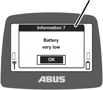
- A message with the information code appears on the display.
Code |
Information |
Cause |
Measure |
|---|---|---|---|
7 |
“Battery very low” |
The batteries are almost empty. |
Replace the batteries. See “Inserting rechargeable batteries”. |
8 |
“Wrong code” |
The code entered is incorrect. |
Press ENTER, and enter the code again. |
9 |
“Scanning for free radio channel...” |
The CHANNEL CHANGE button was pressed. |
Wait until the transmitter has found a free radio channel. |
ABUS Service
Only in Germany
- If available, have the product number, serial number and customer number handy.
- Call the ABUS Service Centre:
- Phone: +49-2261-37-237
- If calling outside the usual business hours, leave a message on the answering machine.
- ABUS Service will return your call promptly.
- If necessary, send a description of the problem by fax or e-mail:
- Fax: +49-2261-37-265
- E-mail: service@abus-kransysteme.de
Only outside Germany
- Call the local ABUS branch or crane service partner.
Your local ABUS branch or crane service partner will provide details of contact data, contacts and availability.
Declaration of Incorporation
This declaration is applicable as a Declaration of Incorporation as described in Machine Directive Annex II 1B in the event that ABURemote is installed or retrofitted in a crane. Starting operation of the crane is then prohibited until it has been ascertained that the crane installation into which the ABURemote has been installed meets all requirements of the EU directive versions applicable at the time of issuance. If ABURemote is delivered together with a complete crane installation, the Declaration of Conformity for the crane installation applies. This Declaration of Incorporation is thereby made irrelevant.
ABUS Kransysteme GmbH Sonnenweg 1 51647 Gummersbach, Germany |
||
|---|---|---|
| Product | ABUS Radio Remote Control ABURemote Joystick in series design |
|
| Year of construction | From 2012 | |
| Order number | See title page | |
| Person responsible for putting together the special technical documentation | Daniel Isenbeck Head of Technology and Development ABUS Kransysteme GmbH Sonnenweg 1 51647 Gummersbach, Germany |
|
| We hereby declare than the product specified above complies with all requirements in the EU directives listed here in the version applicable at the time of issuance. | 2006/42/EC | Machinery |
| 2014/35/EU | Low-voltage | |
| 2014/30/EU | Electromagnetic compatibility | |
| 2014/53/EU | Radio and telecommunications terminal equipment | |
| In particular, the harmonised standards and national standards, directives and specifications and any other applicable standards have been applied. | EN 13849-1 | Safety of machinery |
| EN 13557 | Cranes – Controls and control stations | |
| EN 60204-32 | Electrical equipment of machines, hoisting equipment | |
| EN 61000-6-4 | Electromagnetic compatibility; Emission standard for industrial environments | |
| EN 61000-6-2 | Electromagnetic compatibility; Immunity for industrial environments | |
| EN 60529 | Degrees of protection provided by enclosures (IP code) | |
| EN 300220-2 | Electromagnetic compatibility and Radio spectrum Matters (ERM) – Short Range Devices (SRD) | |
| EN 301489-3 | Electromagnetic compatibility and Radio spectrum Matters (ERM) – Electromagnetic Compatibility (EMC) standard for radio equipment and services | |
Technical documentation is available in full.
The corresponding operating manuals are available in the national language of the user.
With our department for “Technical Documentation”, we have committed ourselves to submitting the specific documentation for the incomplete machine in response to a reasoned request by the market surveillance authorities.
Gummersbach, 23 April 2026
Head of the Electronics Development department
Willi Dick

___________________________
Signature of the authorised person
The content of this declaration complies with EN ISO 17050.
ABUS Kransysteme GmbH supports a quality management system in accordance with DIN EN ISO 9001.