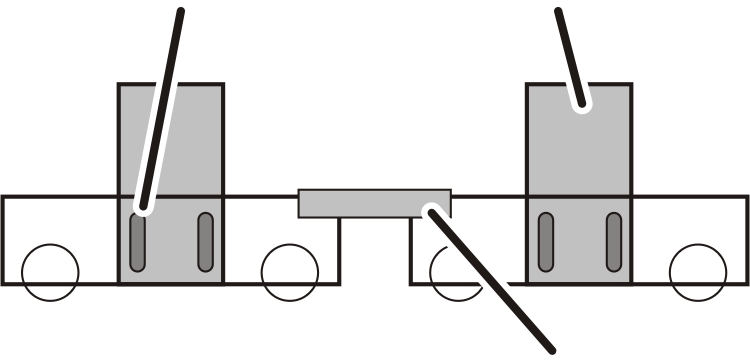
Coupling bar
Main girder
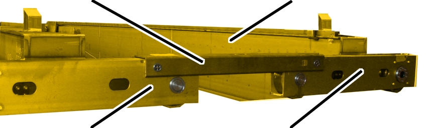
End carriage
End carriage
|
Coupling bar |
Main girder |
|
| |
|
End carriage |
End carriage |
This installation procedure is similar to the installation procedure for a normal double girder travelling crane.
 If the end carriages have not
been fitted on the main girder: Install all four end carriages on the main
girder. See Fixing the end carriages onto
the main girder.
If the end carriages have not
been fitted on the main girder: Install all four end carriages on the main
girder. See Fixing the end carriages onto
the main girder.
If the main girders are
delivered with end carriages fitted: The end carriages are already tightened to
the correct tightening torque.
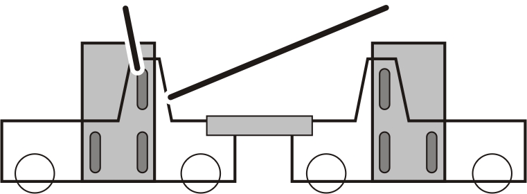
|
Mounting plate |
Main girder |
|
| |
|
|
Coupling bar |
For 8-wheel crane version N: The main girders are (as is the case for a normal double girder travelling crane) screwed to the end carriage using two mounting plates on each side.
|
Mounting plate |
End carriage with welded-on trestle |
|
| |
For 8-wheel crane version H: The main girders are screwed to the end carriage using three mounting plates on each side.
The third mounting plate is screwed onto the welded-on trestle.
|
|
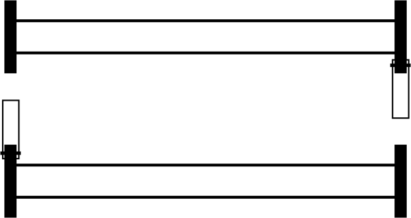
Start by installing one coupling
bar to an end carriage on one side. See the following section.
Then install the other coupling
bar on the opposite side of the other end carriage. See the following
section.
Note:
If it is not possible to fit the coupling bars this way on the ground, the coupling bars can also only be fitted when both main girders are on the crane track.
This work step only applies if the crane is an 8-wheel crane (four individual end carriages joined with a coupling bar) and the end carriage size is 200 to 420.
|
|
Markings |
|
| |
|
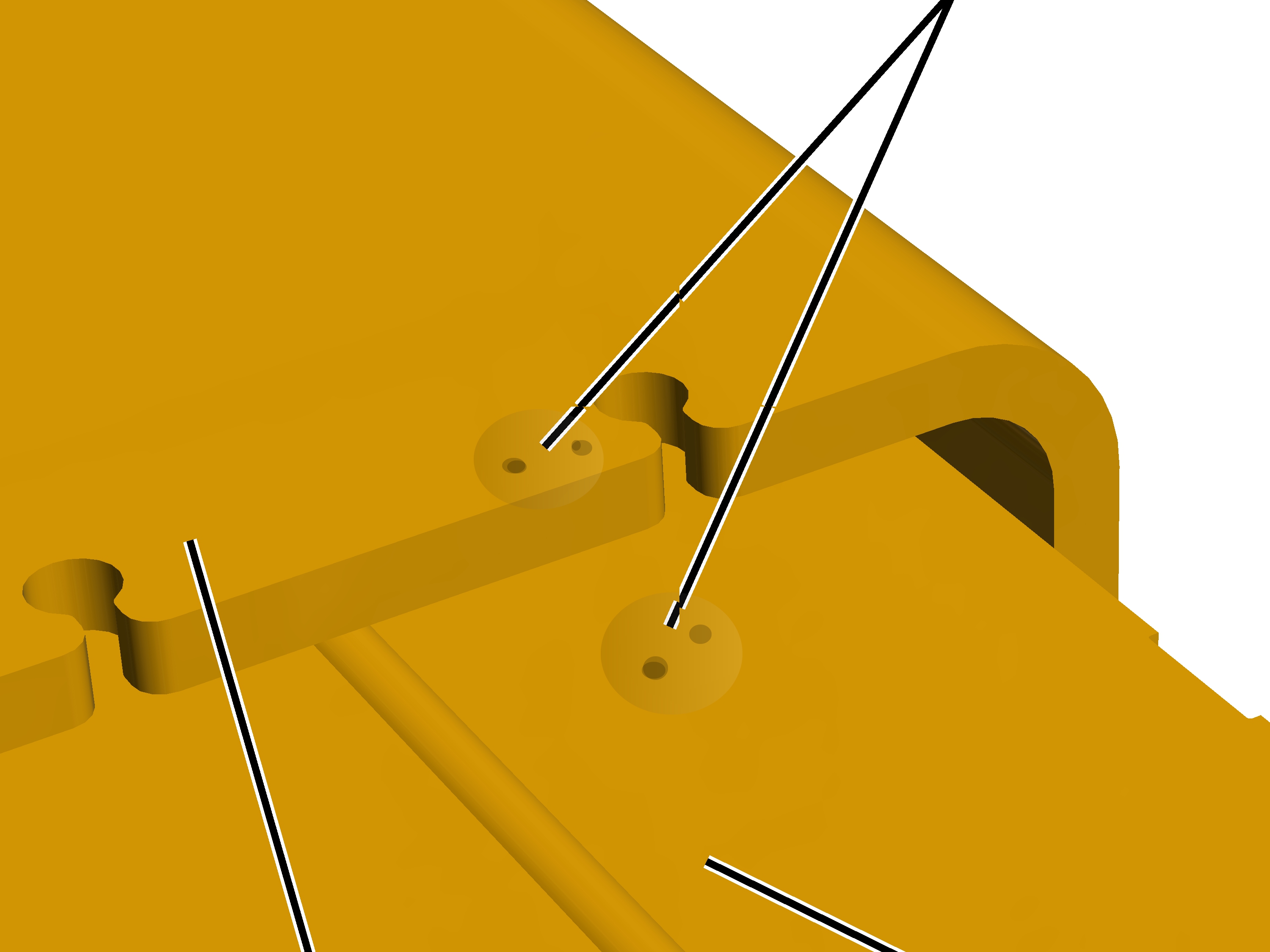
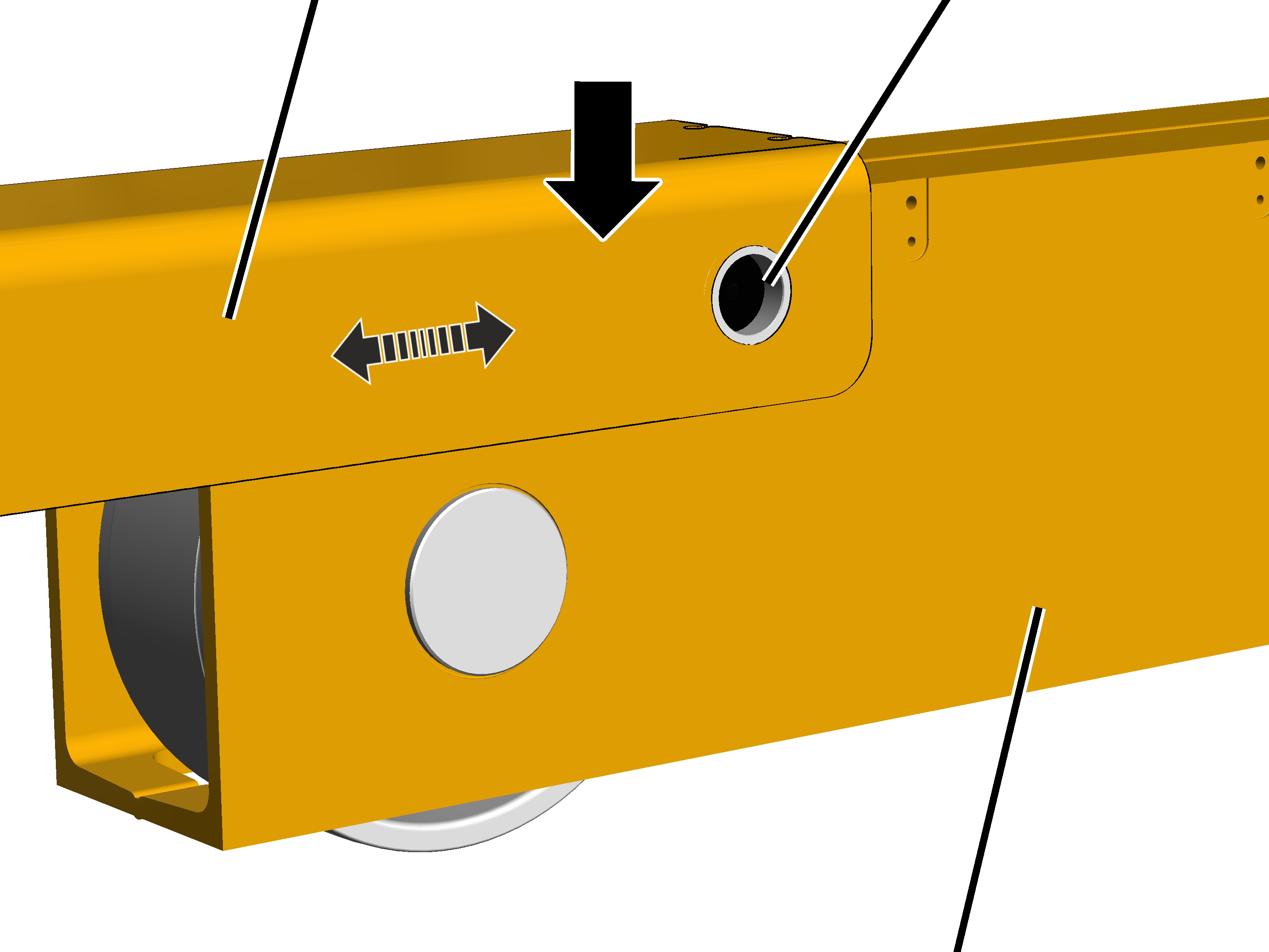
Coupling bar |
End carriage |
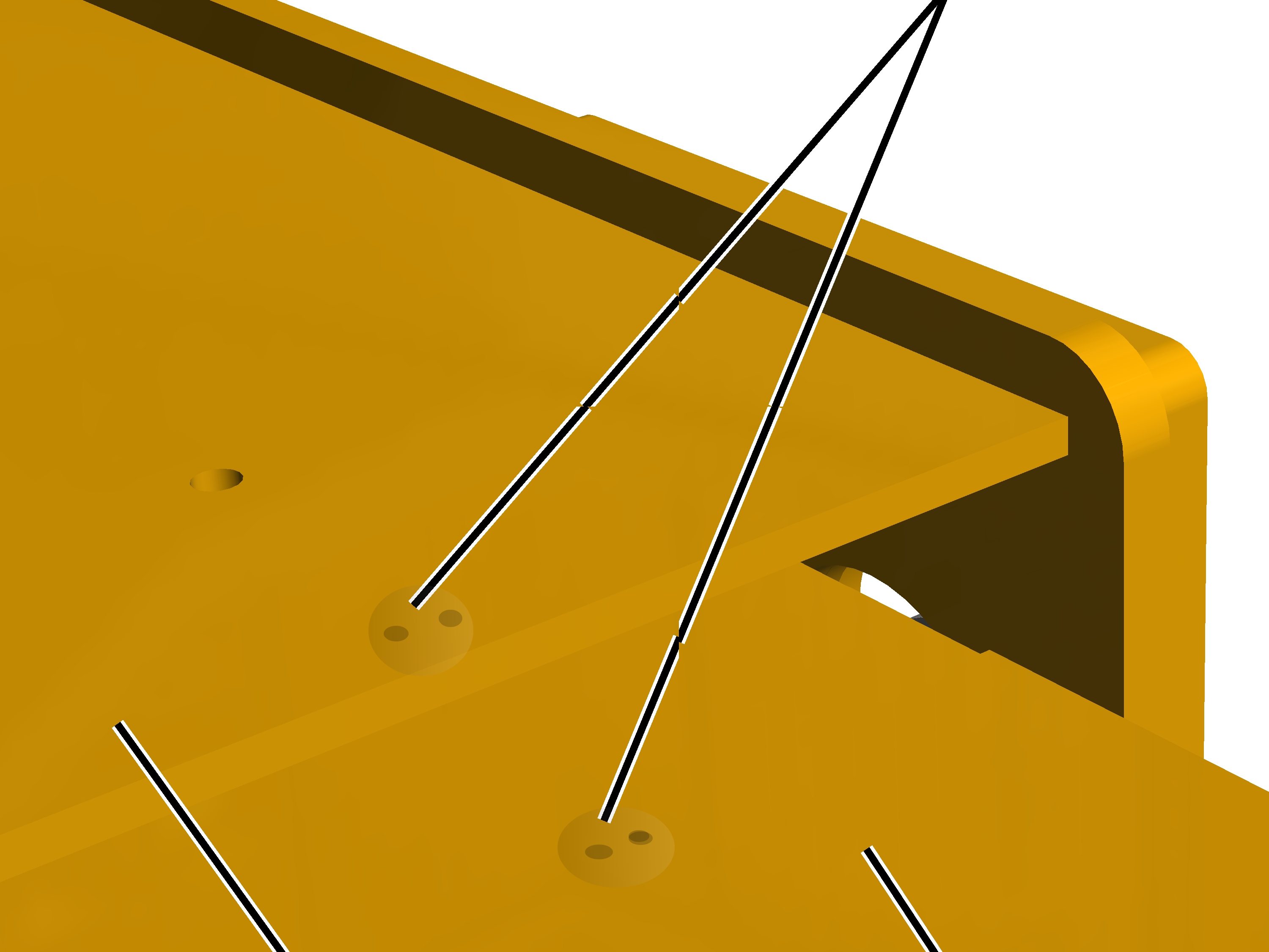
Find the markings (for the
installation direction) on the coupling bars and on the end carriages.
1, 2, 3 or 4 centre markings have been punched in. The number of centre markings must match.
|
Coupling bar |
Bore hole for flanged bolts |
|
| |
|
|
Individual end carriage |
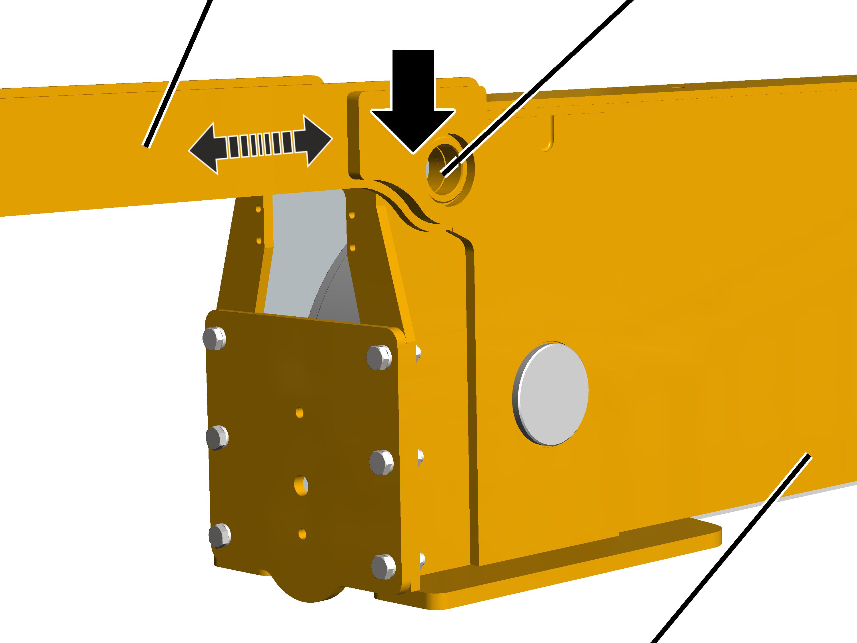
Place the coupling bars on the
end carriage so the markings (for the installation direction) match.
Move the coupling bar so that
the holes for the flanged bolt are on top of one another.
|
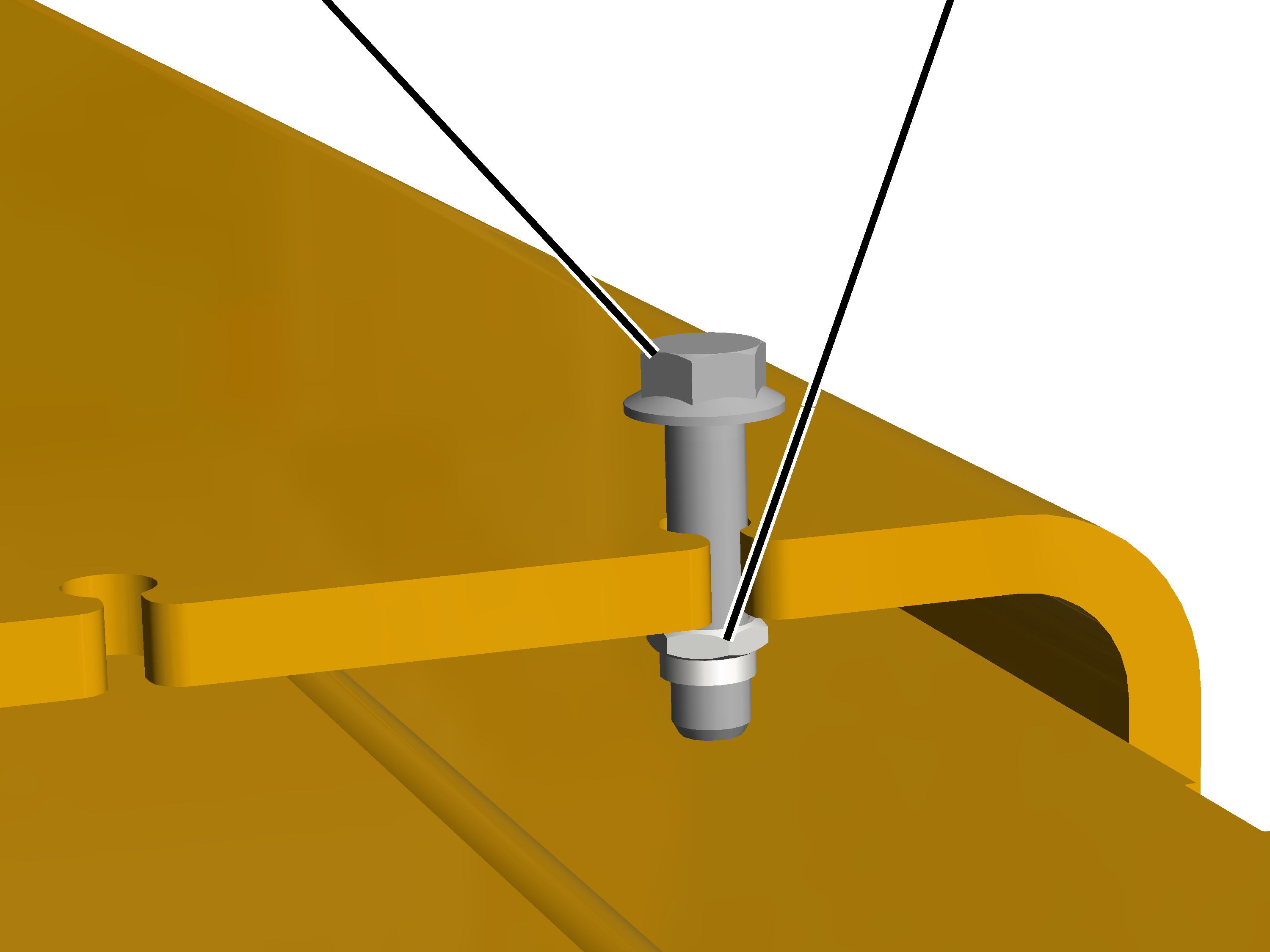
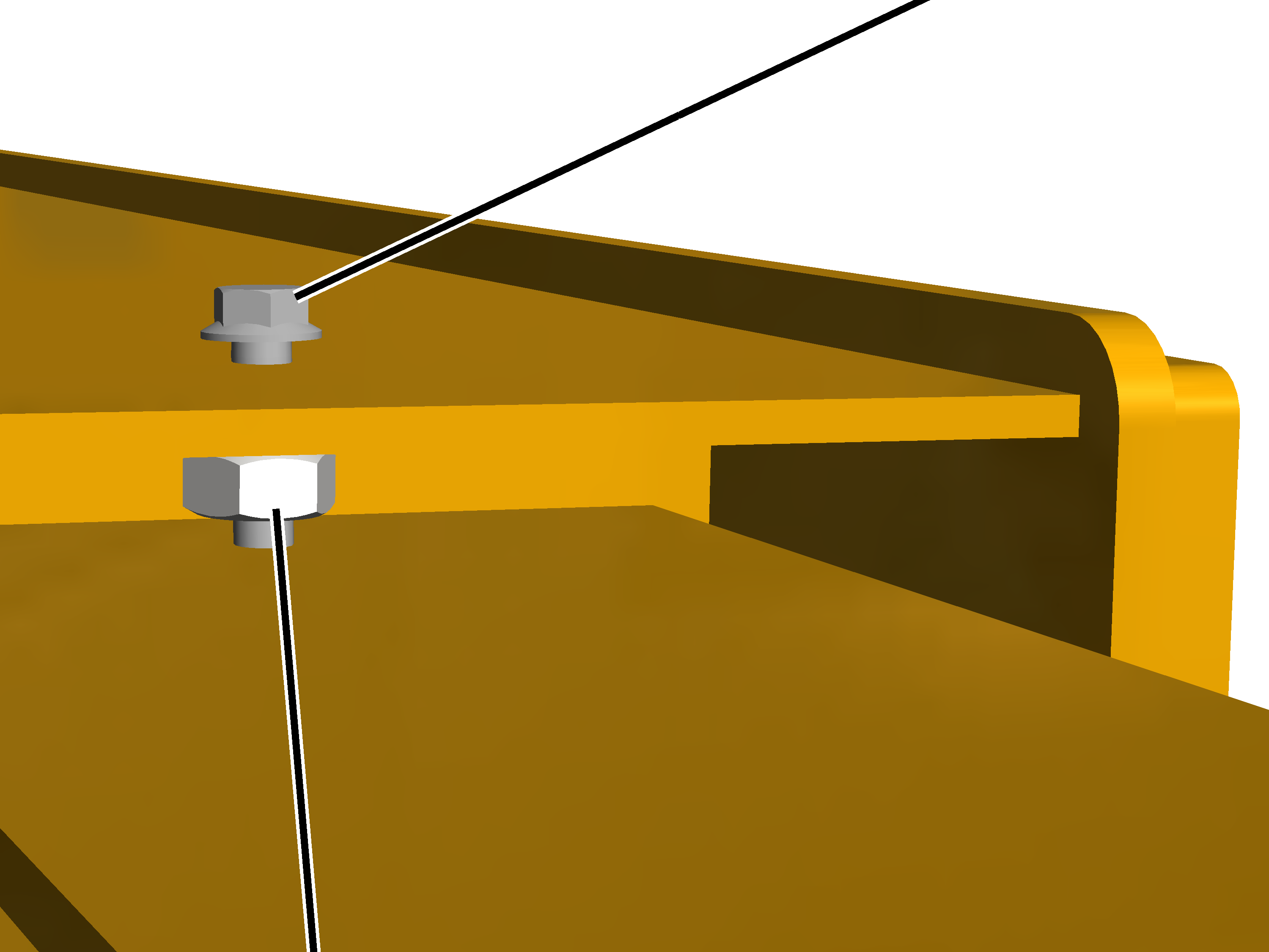
Rib screw M12x50 |
Rib nut M12 |
|
| |
To make positioning the coupling bar easier, insert a rib screw M12x50 with a rib nut M12 into the openings on the edge of the coupling bar and adjust the position of the coupling bar by turning the rib nut.
|
| |
|
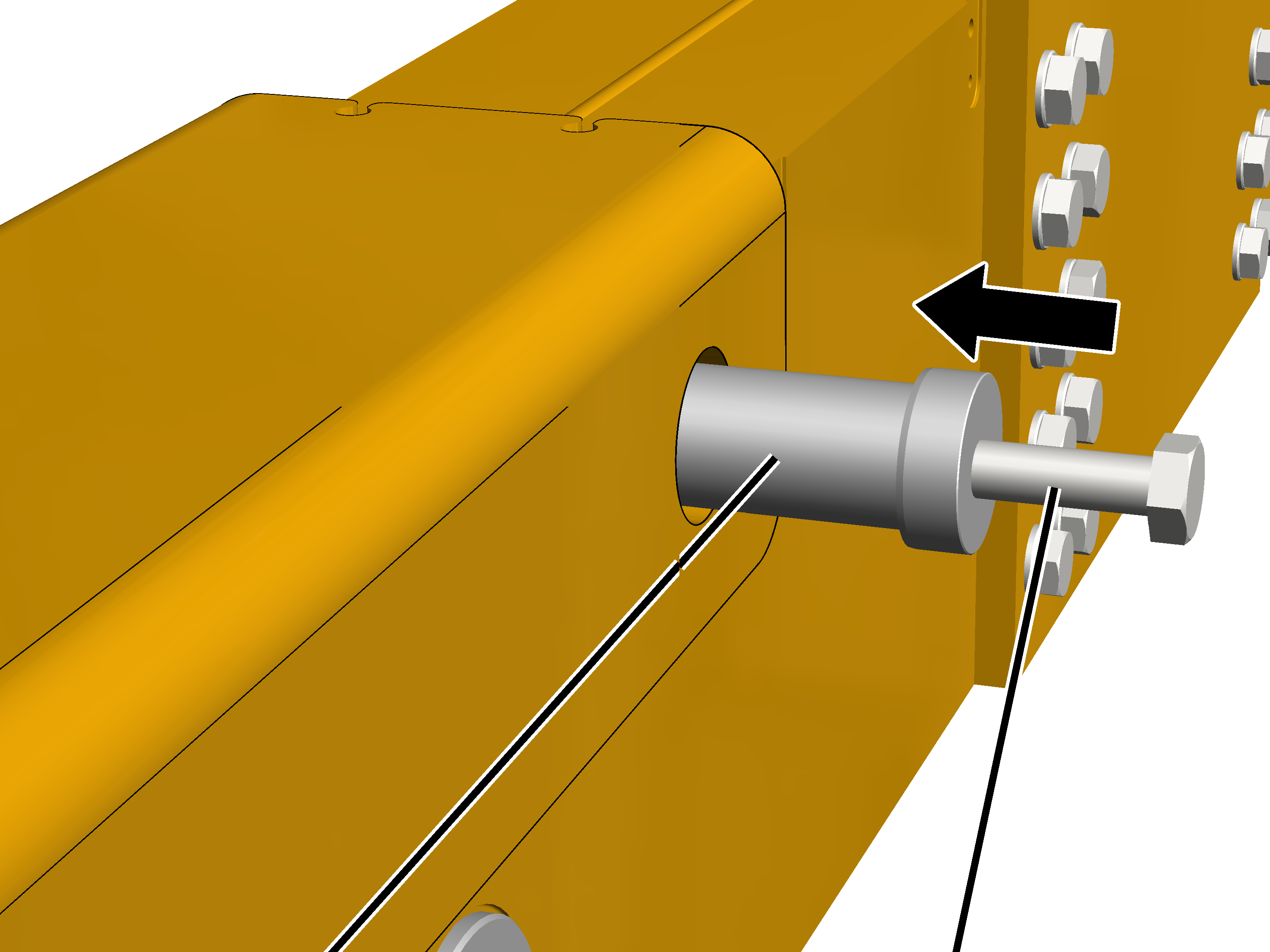
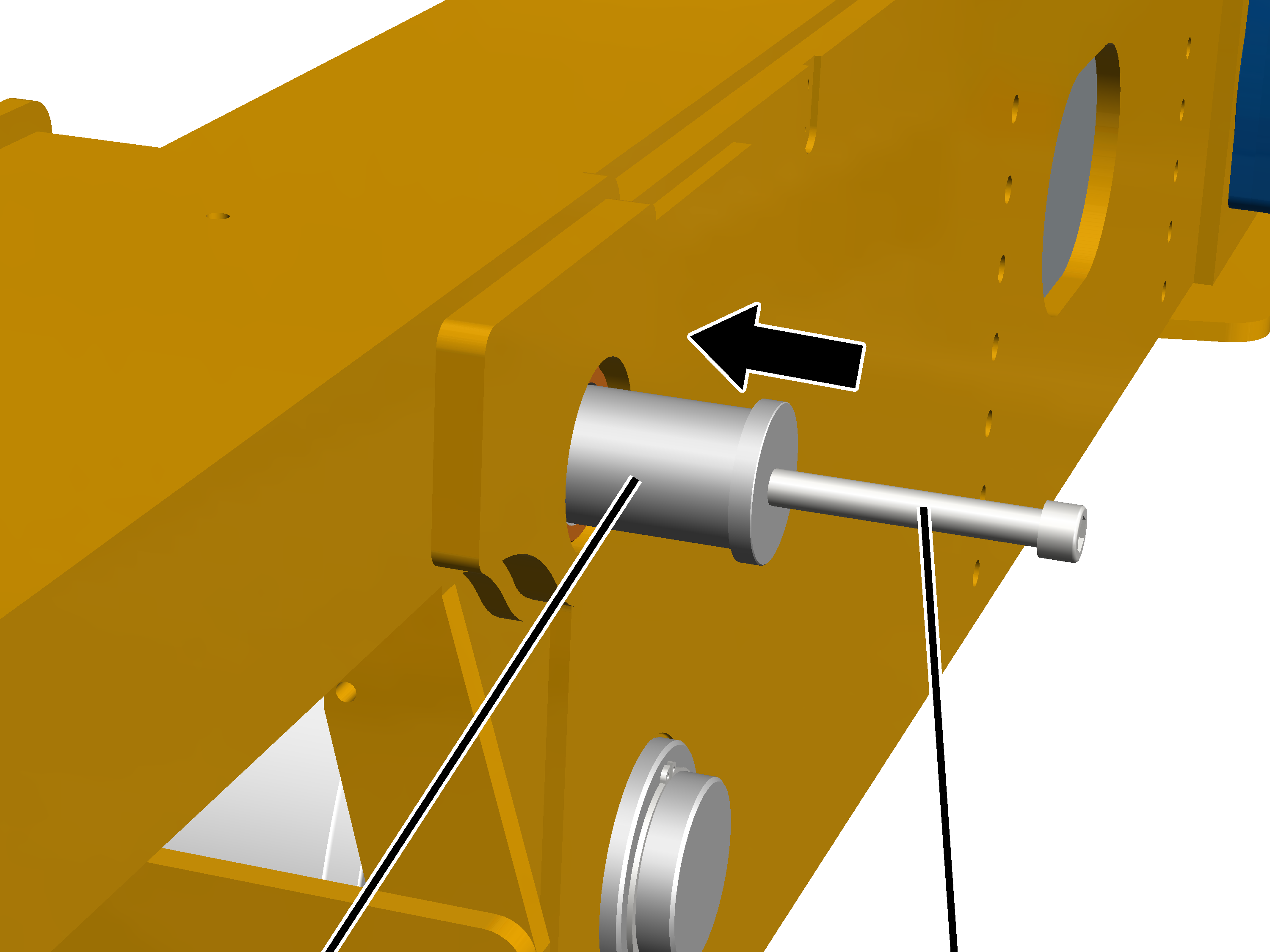
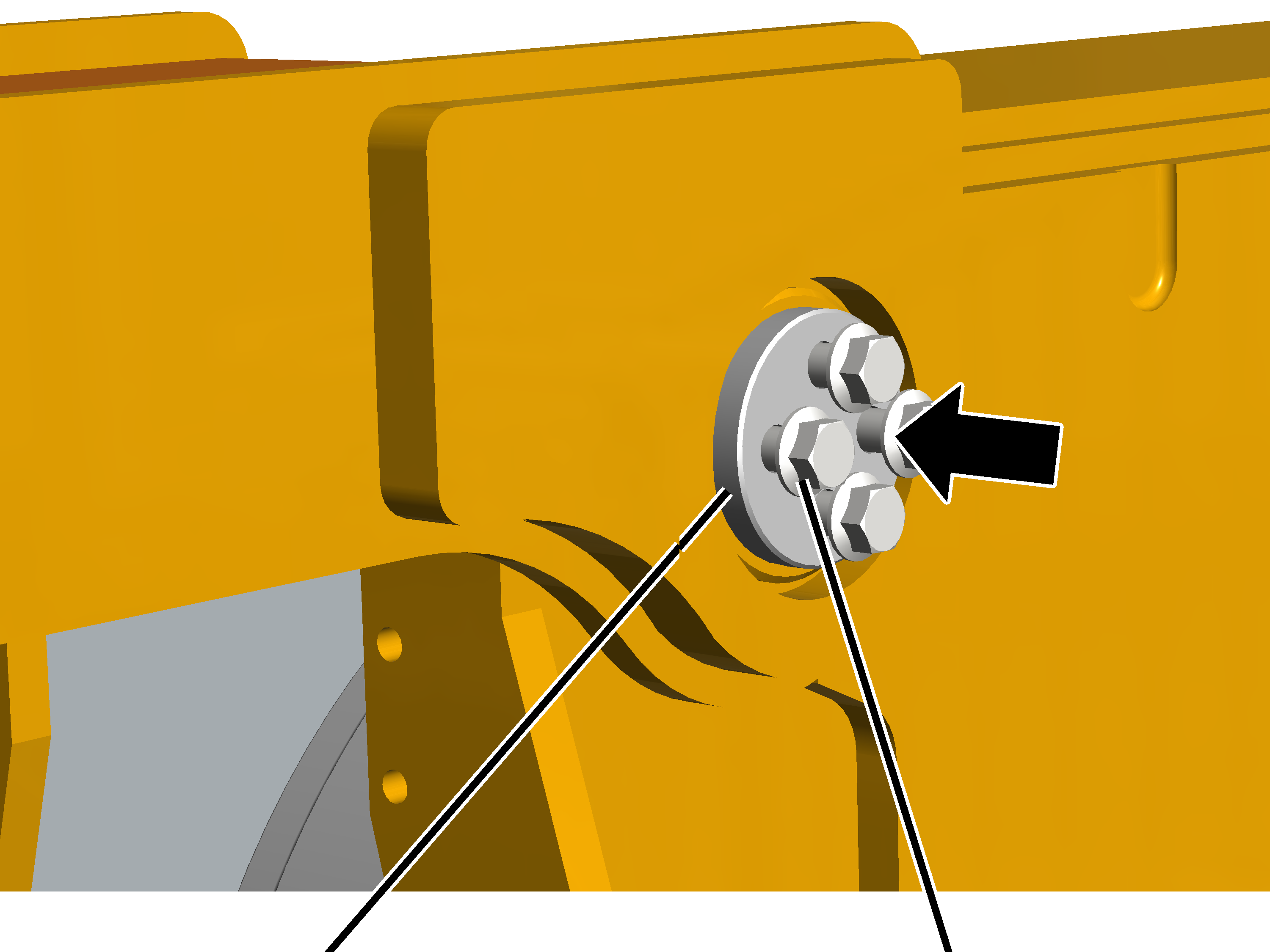
Flanged bolt |
Screw or threaded rod |
Screw a screw M10 or M12 or a
threaded rod into the flanged bolt.
Push the flanged bolt from
inside through the hole.
Guide the flanged bolt with the
aid of the screw or threaded rod, and push it right through the coupling
bar.
|
| |
|
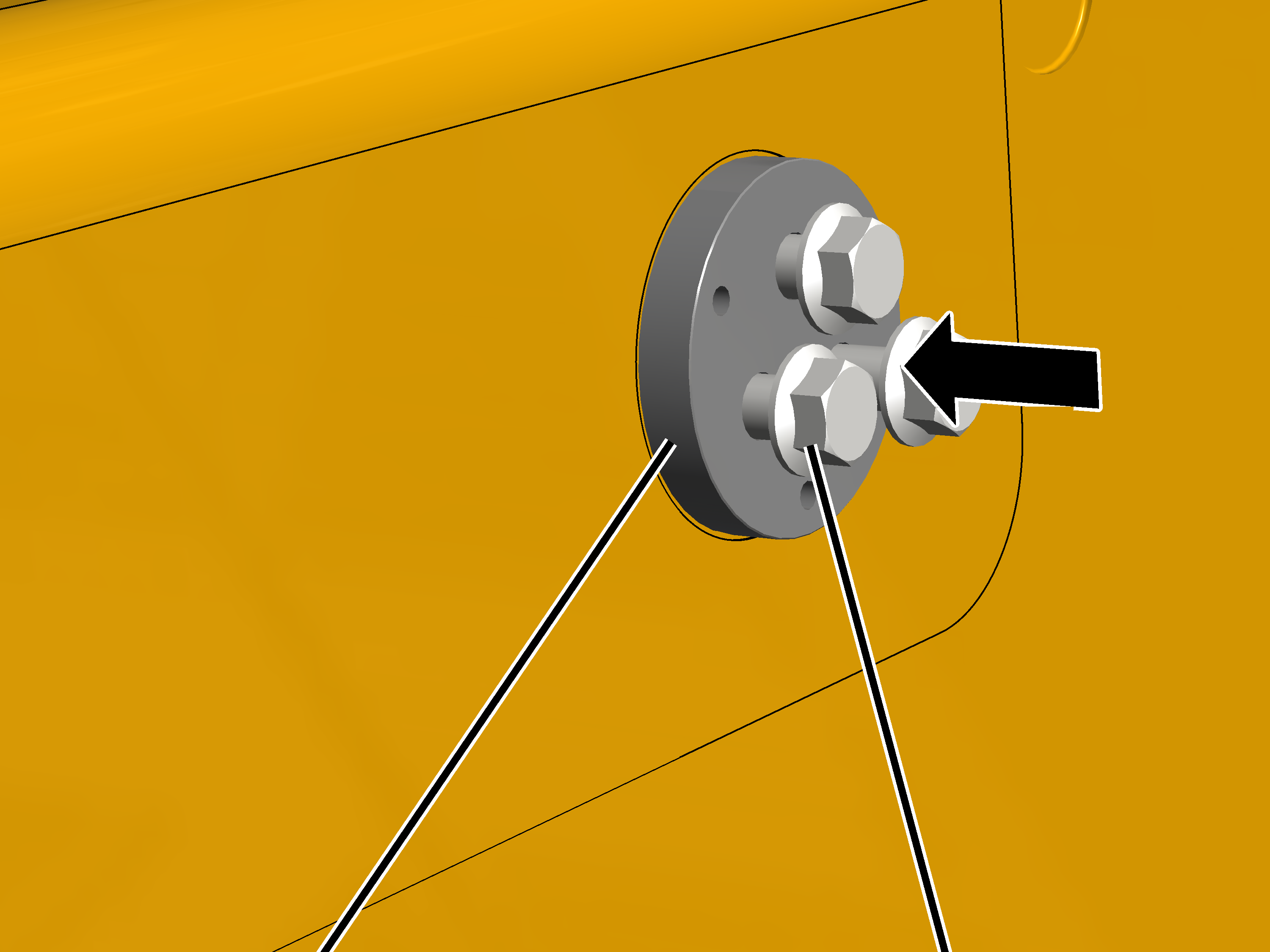
Cover |
Rib screw |
Put on the cover.
Screw the rib screws in.
|
End carriage size |
Type, size and length |
Number |
Tightening torque |
|
200 |
Rib screw M10x20 |
3x |
85 Nm |
|
280 |
Rib screw M12x25 |
3x |
130 Nm |
|
350 |
Rib screw M12x25 |
3x |
130 Nm |
|
420 |
Rib screw M12x25 |
4x |
130 Nm |
This work step only applies if the crane is an 8-wheel crane (four individual end carriages joined with a coupling bar) and the end carriage size is 500.
|
|
Markings |
|
| |
|
Coupling bar |
End carriage |
Find the markings (for the
installation direction) on the coupling bars and on the end carriages.
1, 2, 3 or 4 centre markings have been punched in. The number of centre markings must match.
|
Coupling bar |
Bore hole for flanged bolts |
|
| |
|
|
Individual end carriage |
Place the coupling bars on the
end carriage so the markings (for the installation direction) match.
Move the coupling bar so that
the holes for the flanged bolt are on top of one another.
Tip:
|
|
Rib nut M12 |
|
| |
|
Rib screw M12x50 |
|
To make positioning the coupling bar easier, insert a rib screw M12x50 with a rib nut M12 into the openings on the edge of the coupling bar and adjust the position of the coupling bar by turning the rib nut.
|
| |
|
Flanged bolt |
Screw or threaded rod |
Screw a screw M10 or M12 or a
threaded rod into the flanged bolt.
Push the flanged bolt from
inside through the hole.
Guide the flanged bolt with the
aid of the screw or threaded rod, and push it right through the coupling
bar.
|
| |
|
Cover |
Rib screw |
Put on the cover.
Screw the rib screws in.
|
End carriage size |
Type, size and length |
Number |
Tightening torque |
|
500 |
Rib screw M12x40 |
4x |
130 Nm |
Install further components. See
Installing the safety
buffers.
Lift the two main girders
individually onto the crane track. Align the inner wheels with the coupling bars
as you do so. See Lifting the
overhead travelling crane onto the crane track.
Join the two main girders to
each other on both sides using the coupling bars. See Fitting the coupling
bar.
Install the trolley. See Installing the
trolley.
Install the trolley power
supply. See Installing the trolley power
supply.
Install the mains power supply.
See Installing the mains power
carrying fork (MCF).
Install the crane travel limit
switch. See Installing the cross-type limit
switch.
If the end carriages were not
fitted upon delivery: Screw all four end carriages in place. See Fastening the end
carriages tightly.