If available: Read the position
of the mains power carrying fork from the planning documents (drawing
“Installation position of mains power carrying fork (MCF)”).
If available: Read the position
of the mains power carrying fork from the planning documents (drawing
“Installation position of mains power carrying fork (MCF)”).
Depending on the type of crane and the on-site conditions in the building, the mains power supply is installed differently.
If available: Read the position
of the mains power carrying fork from the planning documents (drawing
“Installation position of mains power carrying fork (MCF)”).
If the drawing is not available: Install the mains power carrying fork as close as possible to the panel. In doing so, observe the required safety clearances of the crane and of the trolley.
Configuration of the mains power carrying fork:
─ For one mount: If the vertical square tube is 80 cm long, a single square tube is used.
For one mount: If the vertical square tube is 100 cm or 130 cm long, two square tubes are used.
For two mounts: If the vertical square tube is 80 cm long, a single square tube is used on each mount.
─ For two mounts: If the vertical square tube is 100 cm or 130 cm long, two square tubes are used on each mount.
With 130 cm long vertical square tubes, the vertical square tubes of both mounts are additionally connected with each other crosswise by means of a square tube.
One or two mounts are now assembled on the left or right of the end carriage, according to the previously selected installation version.
If necessary:
|
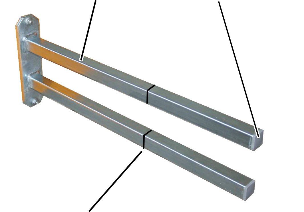
Mount |
Ribbed end cap |
|
| |
|
Shorten mount to required length |
|
Remove the ribbed end caps (2x)
from the mount.
Shorten the mount.
The required length is determined by the on-site conditions in the building and the safety clearances from the crane drawing.
Reinsert the ribbed end caps
(2x) into the ends of the mount.
|
| ||
|
| ||
|
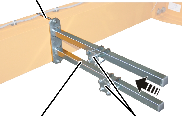
Mount |
Pipe clamp | |
Attach the mount to the end carriage on which
the crane panel is installed.
Bolt the mount onto the threaded bracket.
|
Threaded bracket |
Tightening torque |
|
M8 |
25 Nm |
|
M10 |
50 Nm |
|
M12 |
75 Nm |
Slide on the two pipe clamps and
secure them.
If necessary:
Remove the ribbed end cap from
the square tube.
Shorten the square tube.
Reinsert the ribbed end cap into
the square tube.
|
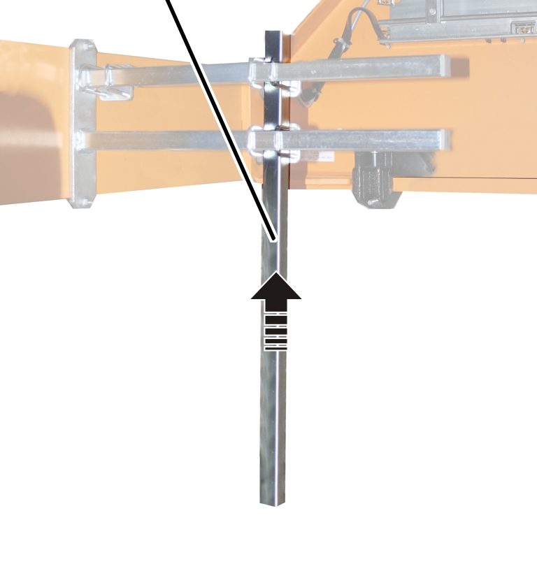
Vertical square tube |
|
|
| |
Move the vertical square tube to the required
position on the mount.
The required length is determined by the on-site conditions in the building and the safety clearances from the crane drawing.
Screw the vertical square tube
onto the mount using pipe clamps (2x). Tighten to 15 Nm.
For more than one vertical square tube:
|
|
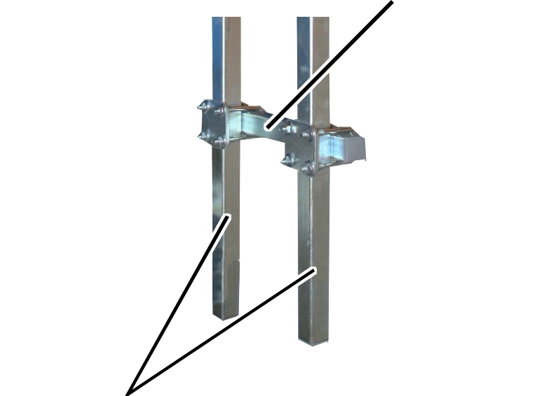
Horizontal square tube |
|
| |
|
Vertical square tube |
|
Attach the horizontal square tube with two pipe
clamps to the vertical square tubes.
The horizontal square tube can be a single square tube or a part of the current collector on the mains power supply.
Tighten the pipe clamps (2x).
Tighten to 15 Nm
The required components are now installed on the prepared mains power carrying fork.
─ Current collector of the mains power supply.
─ Cross-type limit switch. See Installing the cross-type limit switch.
─ Horn
─ Red signal lamp