For
hoists with frequency converters: Move the load hook upwards until the top hoist
limiter switching point is activated.
For
hoists with frequency converters: Move the load hook upwards until the top hoist
limiter switching point is activated.
If the wire rope is damaged or has more wire breaks than permitted (see the "Inspecting the wire rope" section in the "General Product Manual for ABUS Cranes"), it must be replaced.
If the cable guide is damaged (see Inspecting the cable guide), it must be replaced.
The wire rope and cable guides are wearing parts that are subject to heavy loads. They subject each other to wear during operation. This is why the wire rope and cable guide should always be replaced together.
The wire rope is a special lifting rope with a very high breaking strength. This ensures it has a longer service life than a normal wire rope. This is why only genuine wire ropes from ABUS may be used.
If the rope wedge or the rope socket are damaged (see Inspecting the fixed point on the fixed point crosshead (rope socket and rope wedge)), they need to be replaced. They are usually replaced when the wire rope and cable guide are replaced.
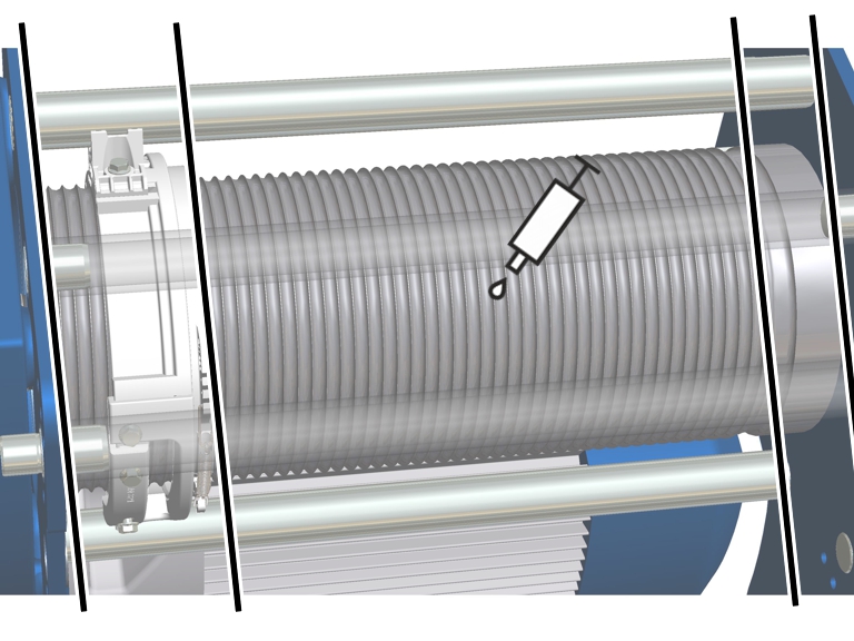
The pictures show the procedure on a GM 1000 modular wire rope hoist. The procedure on GM 800 does not differ significantly from this.
For hoists with contactor control: Move the load hook so that the top hoist limiter switching point is NOT activated.
 Measure, and note, the position
of the load hook.
Measure, and note, the position
of the load hook.
This makes adjusting the hoist limit switch after replacing the wire rope in many cases unnecessary.
|
Cable guide |
|
|
| |
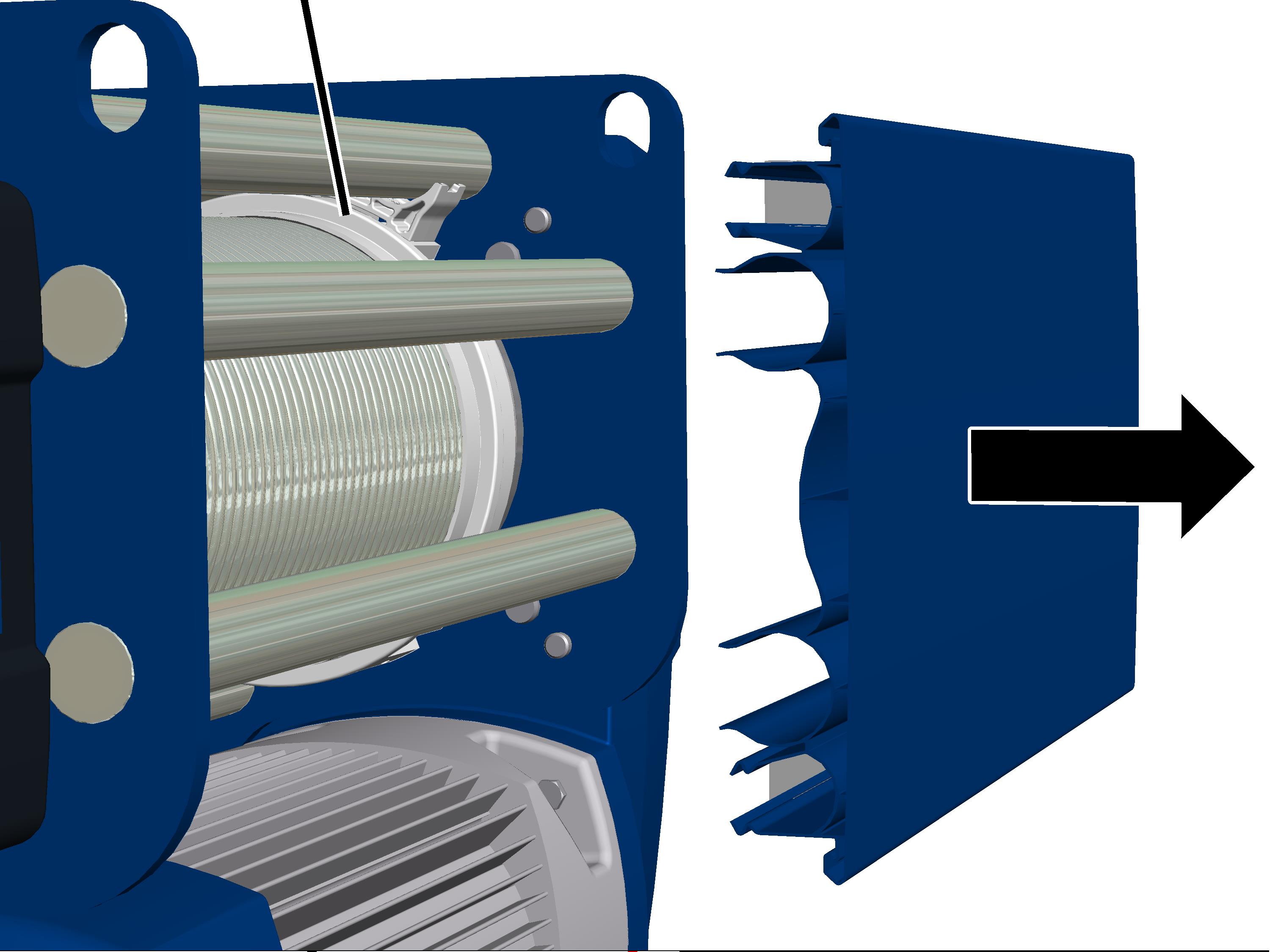
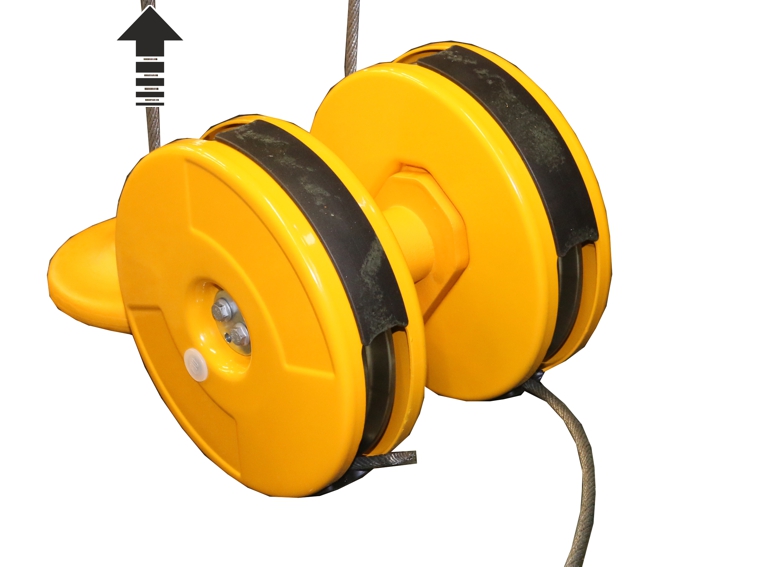
Pull off the cover.
● This provides access to the cable drum and cable guide.
To ensure the wire rope can be unwound from the cable drum using a motor, the hoist limit switch must be removed. Otherwise the cable drum will stop at the lowest hook position.
|
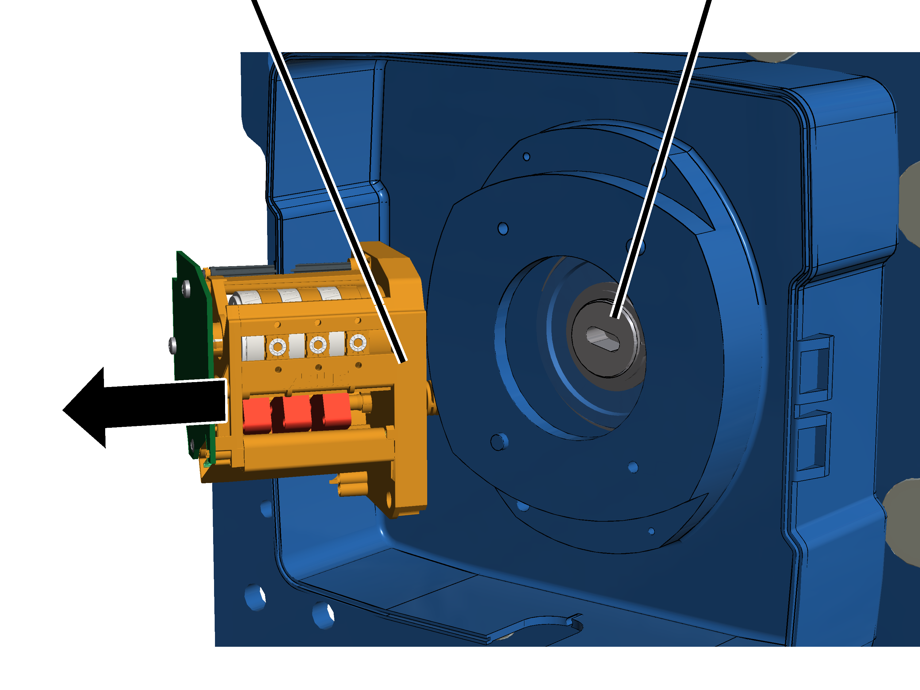
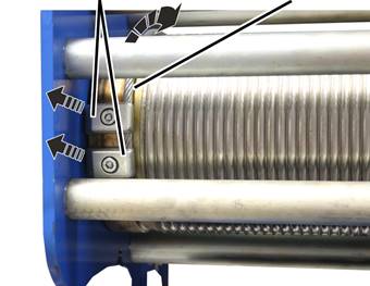
Hoist limit switch |
Pins on the cable drum |
|
| |
Open the
hoist limit switch housing.
Unscrew and remove screws
(2x).
Pull off the hoist limit
switch.
Leave the shaft of the hoist
limit switch in the same position, and do not turn it.
This makes adjusting the hoist limit switch after replacing the wire rope in many cases unnecessary.
If the shaft is accidentally twisted, the message "F_ _ 34 Wire rope change: Absolute rotary encoder 1 not removed" or "F_ _ 33 Wire rope change: Absolute rotary encoder 2 not removed" is displayed.
Secure the hoist limit switch to
ensure it does not fall down or hang from the connection cables.
So that the cable drum can be motor-driven, even though ABUControl does not receive a signal from the absolute rotary encoder (because the hoist limit switch is dismantled with the absolute rotary encoder), the wire rope change must be activated in ABUControl.
|
|
Danger due to bridged safety function During active wire rope change, the load hook can be lifted and lowered without a hoist limit switch being installed. Thus the load hook does not stop at the highest and lowest hook positions. This can cause the wire rope to rip and the load to fall. Only activate rope change if a wire rope is to be changed. |
The wire rope change can be activated in the trolley control by coupling or by KranOS.
Either activate the wire rope change by coupling:
|
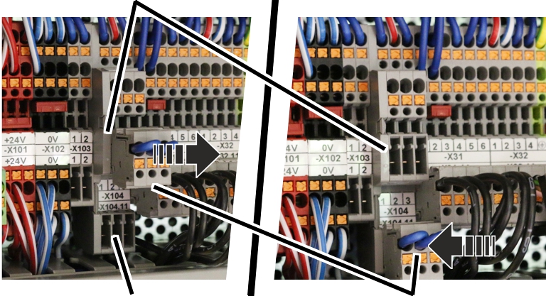
Pin multipoint connector for parking |
|
|
| |
|
Pin multipoint connector for wire rope change |
Coupling with jumper |
Open trolley control.
Search for prong terminal block
-X104.
Remove the coupling from the
parking position (upper pin multipoint connector).
Insert coupling on the upper pin
multipoint connector.
● The wire rope change is activated. The cable drum can now be motor-run without ABUControl receiving a signal from absolute rotary encoder.
● The message "F_ _ 28: Wire rope change activated" is displayed.
● All the wear values for calculating the maximum acceptable wear are deleted so that the calculation for the new wire rope can start over.
Or activate rope change via KranOS:
See the ABUControl product manual.
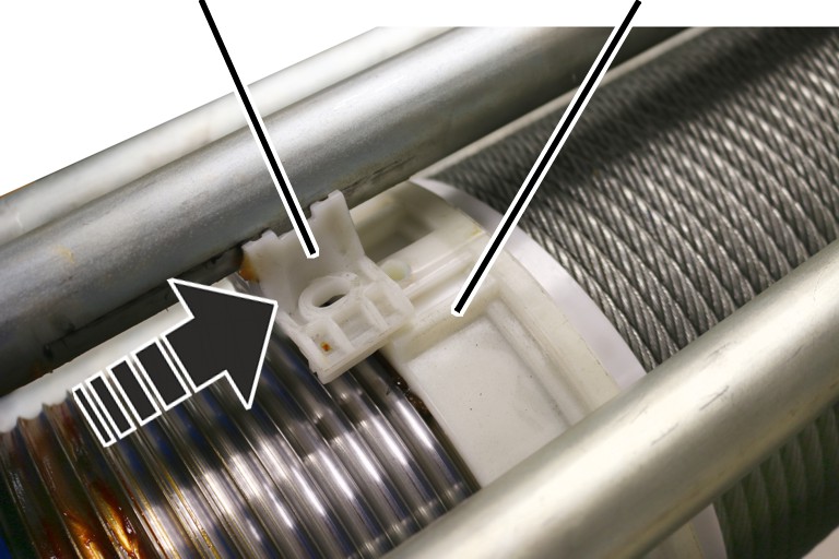
|
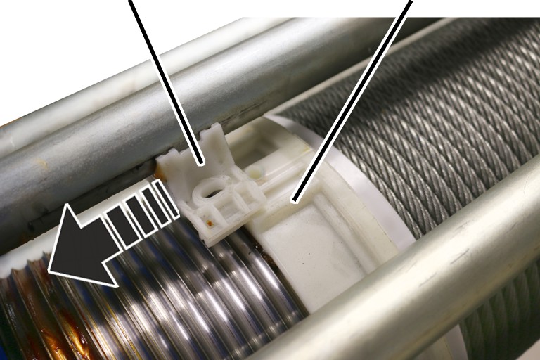
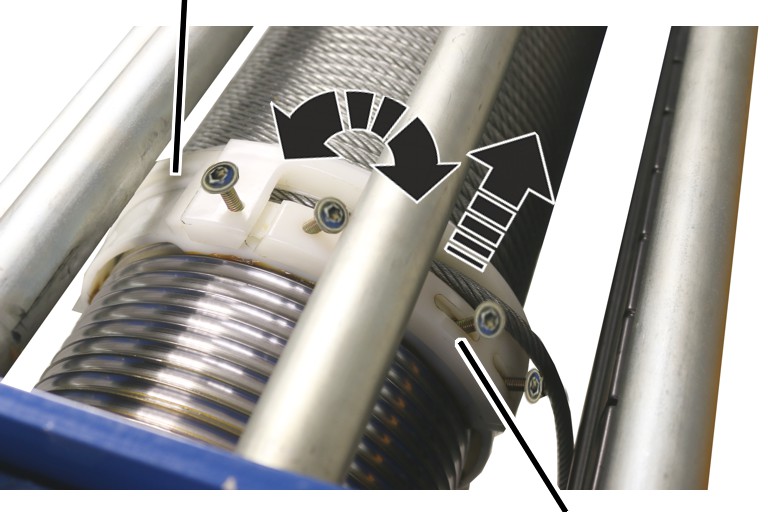
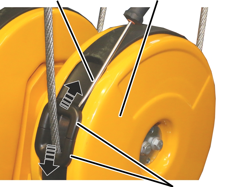
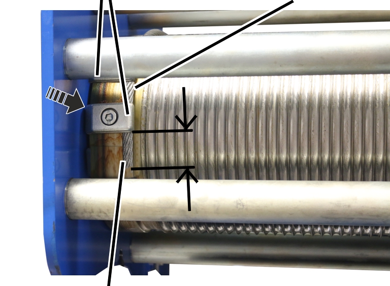
Rope guide runner |
Rope guide ring |
|
| |
Unscrew the rope guide
runner.
Push the rope guide runner away
to one side of the rope guide ring.
● The rope guide ring can now be turned freely on the cable drum.
|
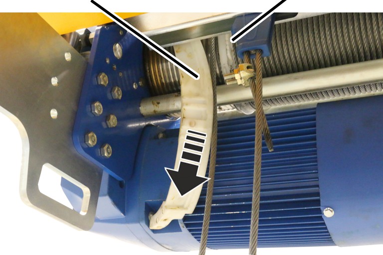
Rope guide ring |
|
|
| |
|
|
Joining element |
Turn the rope guide ring so that
the screws (4x) are easily accessible (e.g. upwards).
Loosen screws (4x).
Remove the joining element and
unthread it from the wire rope.
|
Rope guide ring |
Rope tension ring |
|
| |
Force the rope guide ring apart
and pull it inwards and off the cable drum.
|
Rope tension ring |
|
|
| |
Remove the tension spring from
the rope tension ring.
Force the rope tension ring
apart and pull it inwards and off the cable drum.
● The cable guide has now been disassembled. The wire rope is now lying loose on the cable drum.
|
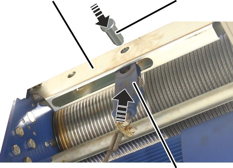
Fixed point crosshead |
Bolt |
|
| |
|
|
Rope socket |
Remove the SL safety clip on the
fixed point crosshead.
Pull the bolt out of the fixed
point crosshead.
Pull the rope socket with the
wire rope out of the fixed point crosshead from the bottom.
If the rope socket and rope wedge are to be used again:
|
Rope socket |
Dead end rope grip |
|
| |
|
Rope wedge |
|
Release the dead end rope
grip.
Drive the rope wedge with the
wire rope out of the rope socket from the bottom.
Take the rope wedge out of the
grommet.
Pull the wire rope out of the
rope socket.
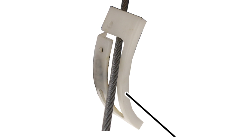
The rope guard in the bottom block will be damaged if the wire rope is pulled along the rope guard quickly to remove it from the bottom block. If the rope guard is to be used again, then the rope guard should be disassembled beforehand.
ABUS recommends replacing the rope guard together with the wire rope.
On all openings on the bottom block:
|
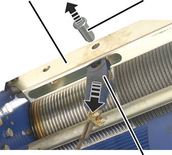
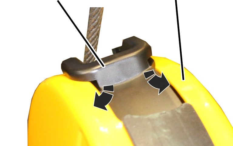
Screwdriver |
Bottom block cover |
|
| |
|
|
Rope guard |
Insert the screwdriver between
the rope guard and bottom block cover at the side, as shown in the figure.
Use the screwdriver to unhook
the load hooks on the left and right of the rope guard at the same time.
Pull the rope guard (2x) apart
and remove it from the bottom block.
|
|
Fit the bottom block.
Pull the wire rope out of the
bottom block.
|
End clamps |
Wire rope |
|
| |
Allow the wire rope to run off
the cable drum using the motor.
● The cable drum only turns at a slow lifting speed once it passes the switching point for the lowest hook position.
Release the end clamps (2x).
Remove the wire rope from the
cable drum completely.
Clean the cable drum.
|
|
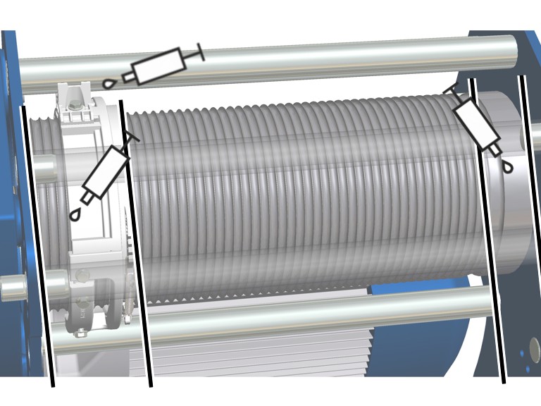
Lubrication on the cable
drum:
─ Lubricate the cable drum from the start to about the 8th or 10th turn.
─ Lubricate the cable drum behind the last turn (the area that does not come into contact with the wire rope).
─ Pipe of side panel (the area which comes into contact with the rope guide runner) and rope guide runner of cable guide.
Lubricant: “Molykote PG-75”. For details, see Lubricants.
|
|
Lubricate the wire rope and
cable drum behind the 8th to 10th turn up to the last turn:
Lubricant: “Chainlife S”. For details, see Lubricants.
|
|
Roll out the wire rope without twisting it! The wire rope will bend and become damaged if it is unrolled incorrectly. Do not pull the wire rope upwards from a horizontal wire rope ring. Unroll the wire rope ring vertically instead, and allow the wire rope to run onto the cable drum in the same direction as it was rolled on the wire rope ring. |
|
End clamps |
Wire rope |
|
| |
|
Rope protrusion |
|
Unroll the wire rope without
twisting it.
Thoroughly clean the
fillister-head screws of the end clamps.
The fillister-head screws were previously bolted with a thread lock coating or a thread lock. The residues must be completely removed before the fillister-head screw may be used again.
The thread lock coating as well as the thread lock are single-use only.
Push the wire rope under the end
clamps far enough that the rope protrusion is about 30 mm.
Tighten the end clamps (2x) with
fillister-head screws and secure with (medium strength) thread lock.
|
Size |
Fillister-head screw |
Tightening torque |
|
GM 800 |
M6x16 |
10 Nm |
|
GM 1000 |
M8x20 |
25 Nm |
Tauten the wire rope and use the
motor to wind it onto the cable drum by 6 to 8 turns, ensuring it is taut and
not twisted.
|
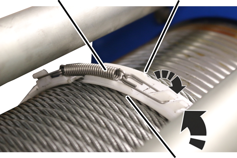
Tension spring |
Ridge |
|
| |
|
|
Rope tension ring |
Turn the rope tension ring so
that the ridge is facing the hoisting gear.
Spread the rope tension ring and
guide it over the wire rope on the cable drum.
Hook the tension spring into one
of the notches so that the rope tension ring is firmly seated on the wire rope
but can still be turned freely.
|
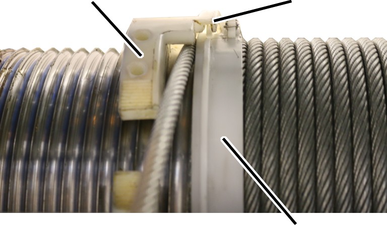
Rope guide ring |
Groove and ridge |
|
| |
|
|
Rope tension ring |
Force the rope guide ring apart
and push it over the cable drum.
Place the rope guide ring with
the groove into the ridge on the rope tension ring.
Place the rope guide ring with
the threaded segments into the free section of the cable drum.
Check that the rope guide ring
is only seated in one groove of the cable drum (the ends of the rope guide ring
form one line).
The ends of the rope guide ring must be aligned.
|
| |
|
|
Joining element |
Thread the joining element onto
the wire rope.
Push the joining element upwards
and place it onto the rope guide ring.
Tighten the joining element.
|
Size |
Screw |
Number |
Tightening torque |
|
GM 800 |
Self-tapping screw 60x16 |
4x |
5 Nm |
|
GM 1000 |
Self-tapping screw 60x16 |
4x |
5 Nm |
|
Rope guide runner |
Rope guide ring |
|
| |
Turn the rope guide ring as far
as is shown in the figure.
Push the rope guide runner under
the tube on the side panel and into the rope guide ring.
Tighten the rope guide runner.
|
Size |
Screw |
Number |
Tightening torque |
|
GM 800 |
Self-tapping screw 60x16 |
1x |
5 Nm |
|
GM 1000 |
Self-tapping screw 60x16 |
1x |
5 Nm |
|
| |
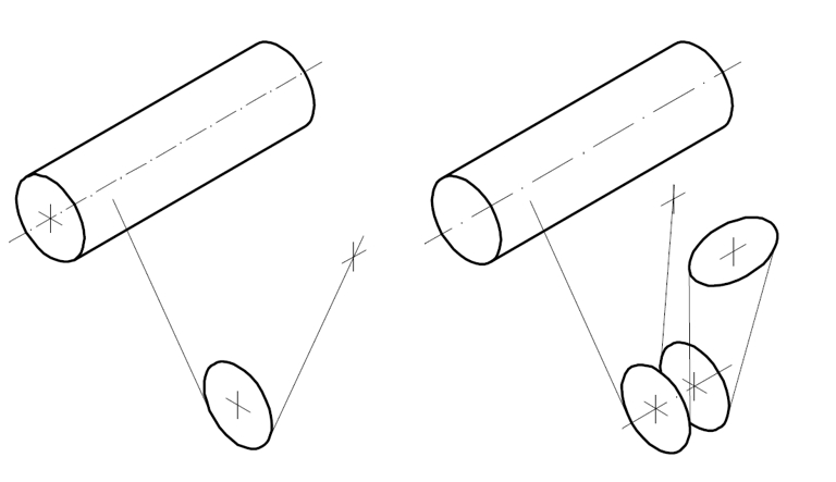
|
Reeving 2/1 |
Reeving 4/1 |
For reeving 2/1: Pull the wire
rope from the cable drum and through the bottom block, without twisting it.
For reeving 4/1: Pull the wire
rope from the cable drum and through the bottom block, without twisting it, and
through the deflection roller and once again through the bottom block.
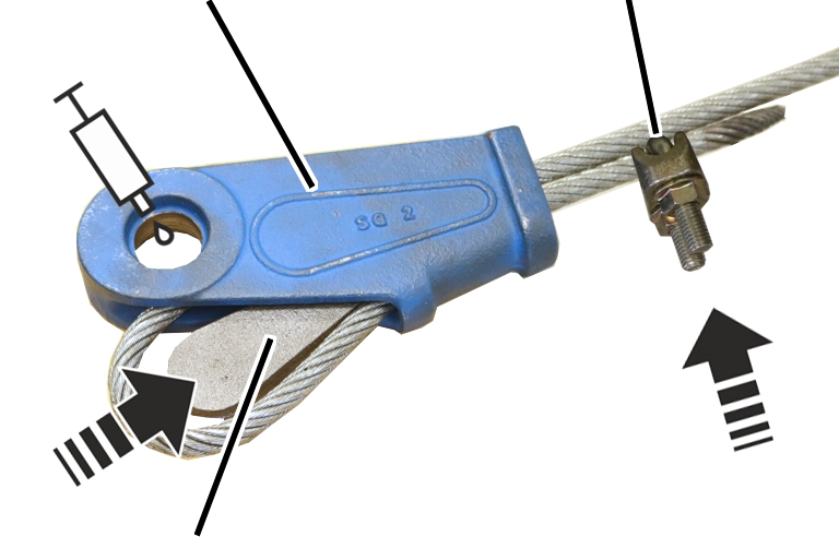
If the rope socket and the rope wedge are still in good condition (see Inspecting the fixed point on the fixed point crosshead (rope socket and rope wedge)), they can be used again. Otherwise use a new rope socket and rope wedge.
|
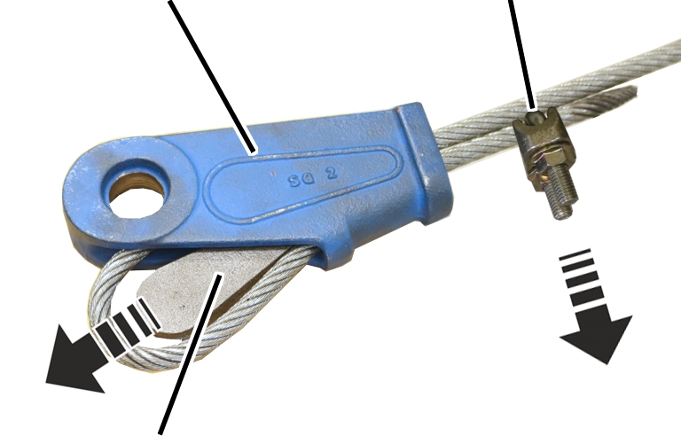
Rope socket |
Dead end rope grip |
|
| |
|
Rope wedge |
|
Double up the wire rope and
thread it through the rope socket from below.
Place the rope wedge in the
loop.
Pull the wire rope downwards
with force.
● The rope wedge slips into the rope socket and clamps the wire rope.
● The rope wedge later becomes finally fixed when a larger load is hung in the hook.
Clean and lubricate the drilled
hole in the rope socket.
Lubricant: “High temperature paste PBC 1574”. For details, see Lubricants.
Push the dead end rope grip onto
the wire rope end and tighten it.
|
Size |
Wire rope |
Rib nut |
Number |
Tightening torque |
|
GM 800 |
Ø 6.5 mm |
M6 |
2x |
5 Nm |
|
GM 1000 |
Ø 8.0 mm |
M8 |
2x |
10 Nm |
|
Fixed point crosshead |
Bolt |
|
| |
|
|
Rope socket |
Lubricate the drilled hole in
the rope socket.
Lubricant: “High temperature paste PBC 1574”. For details, see Lubricants.
Push the rope socket into the
fixed point crosshead, without twisting it, from below.
Insert the bolt into the fixed
point crosshead and rope socket, and secure it using SL safety clips.
On all openings on the bottom block:
|
|
Connecting profile |
|
| |
|
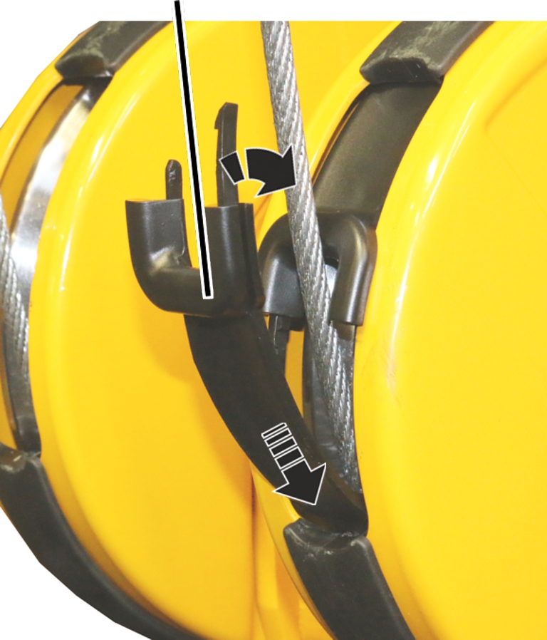
Rope guard |
|
Hold the rope guard on the wire
rope as shown in the figure.
Push the rope guard down along
the wire rope with the front fork and bring the rear end under the connecting
profile.
|
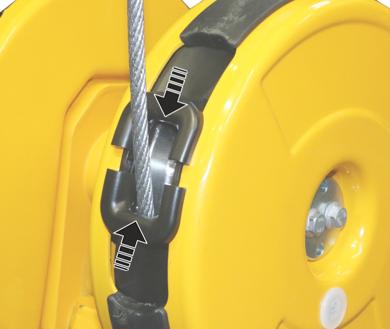
Rope guard |
Bottom block cover |
|
| |
First push the rope guard on the
side with the short bracket into the bottom block cover.
Then push the rope guard on the
side with the long bracket into the bottom block cover.
|
Rope guard |
|
|
| |
Push the second rope guard at
the bottom into the connecting profile.
Push the rope guard downwards
behind the connecting profile and attach it to the top of the wire rope.
First push the rope guard on the
side with the short bracket into the bottom block cover.
Then push the rope guard on the
side with the long bracket into the bottom block cover.
|
|
Connect the lugs of the rope
guard (2x) and push them together.
Attach the cover to the cable
drum.
Use the motor to roll up the
wire rope completely.
Move the load hooks to the
position you noted previously.
Connect the hoist limit switch
to the pins on the cable drum.
Screw the hoist limit switch
tight.
Check the positions of the
switching points.
As soon as the wire rope has been changed:
Remove the coupling from the
lower pin multipoint connector on the prong terminal block -X104 and insert in
the parking position (upper pin multipoint connector).
or
Click on the "Rope change cable drum 1" button.
● The wire rope change is switched off.
● The button's background is no longer green.
To acknowledge the message
"F_ _ 28: Wire rope change activated", press the emergency stop button
or horn.
If the switching points have moved:
Normally, the adjustment of the hoist limit switch after replacing the wire rope can in many cases be omitted, since the position of the load hook was previously measured and then travelled to again. In special cases (e.g. if the wire rope is severely damaged or has been incorrectly rolled onto the cable drum), the switching points may need to be readjusted.
Reset switching points for the
bottom hoist limiter, the top hoist limiter and the backup limiter.
See the ABUControl product manual.
Suspend the load from the load
hooks, raise it and load the wire rope this way.
Measure the rope wedge
protrusion and check whether the dimensions specified in the table have been
complied with.
|
Size |
Rope wedge protrusion when the wire rope hoist is new |
Maximum rope wedge protrusion |
Minimum rope clamp spacing |
|
GM 800 |
18 mm |
19 mm |
6.5 mm |
|
GM 1000 |
3 mm |
4 mm |
8 mm |