Run the load hook to the highest
hook position.
Run the load hook to the highest
hook position.
If the wire rope is damaged or has more broken wires than permitted (see Inspecting the wire rope), it must be replaced.
If the cable guide is damaged (see Inspecting the cable guide), it must be replaced.
The wire rope is a special lifting rope with a very high breaking strength. This ensures it has a longer service life than a normal wire rope. This is why only genuine wire ropes from ABUS may be used.
If the rope wedge or the rope socket are damaged (see Exchanging the fixed point crosshead with rope socket and rope wedge), they need to be replaced. They are usually replaced when the wire rope and cable guide are replaced.
These safety instructions apply specifically to changing the wire rope:
─ Cordon off a generous space for the work area under the wire rope hoist.
─ Ensure the floor is swept clean.
This reduces soiling of the new wire rope.
─ Scissors lift platform with adequate surface area for setting down the bottom block.
Observe the load capacity of the lift platform!
─ If an unrolling device is available to unroll the wire rope, sufficient free space for this is required.
─ Position a scrap container or similar receptacle in the immediate vicinity of the lift platform and bottom block for the old wire rope.
─ For a wire rope diameter larger than 11 mm, the rope change should be performed with the aid of a second person.
Run the load hook to the highest
hook position.
Only with ABUS electrics 3 with ABULiner: move the load hook under the upper limit switch range.
Measure, and note, the position of the load
hook.
This makes adjusting the hoist limit switch after replacing the wire rope in many cases unnecessary.
If ABUControl is installed for the wire rope hoist, refer to the product manual “ABUControl”, section “Exchanging the wire rope” to prepare for the rope change.
Further steps for the wire rope change are then described in this product manual.
|
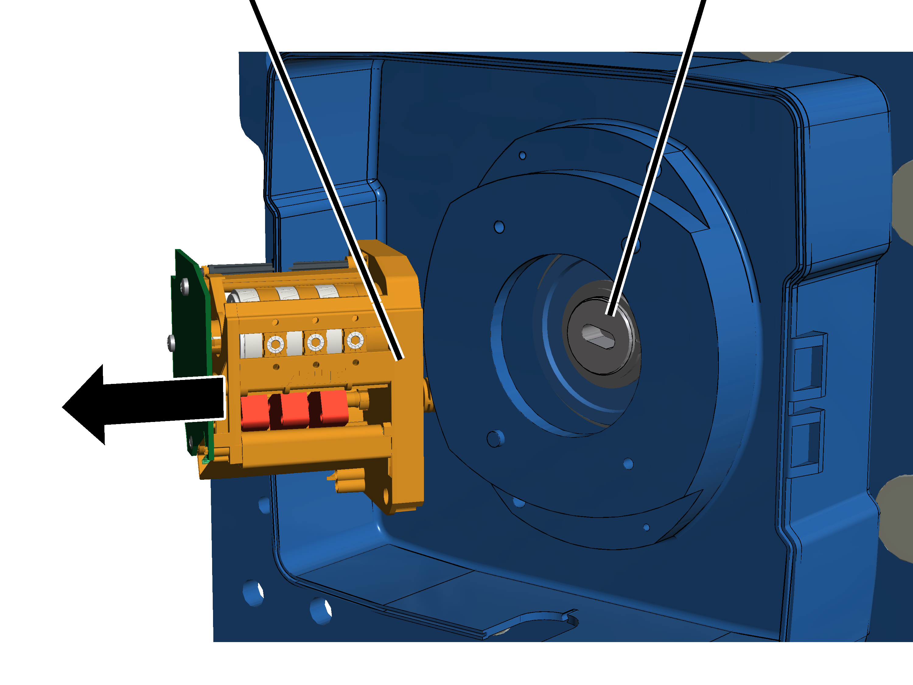
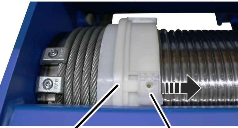
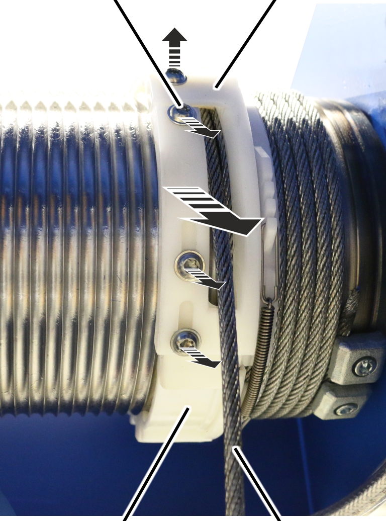
Hoist limit switch |
Pins on the cable drum |
|
| |
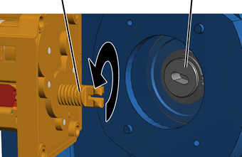
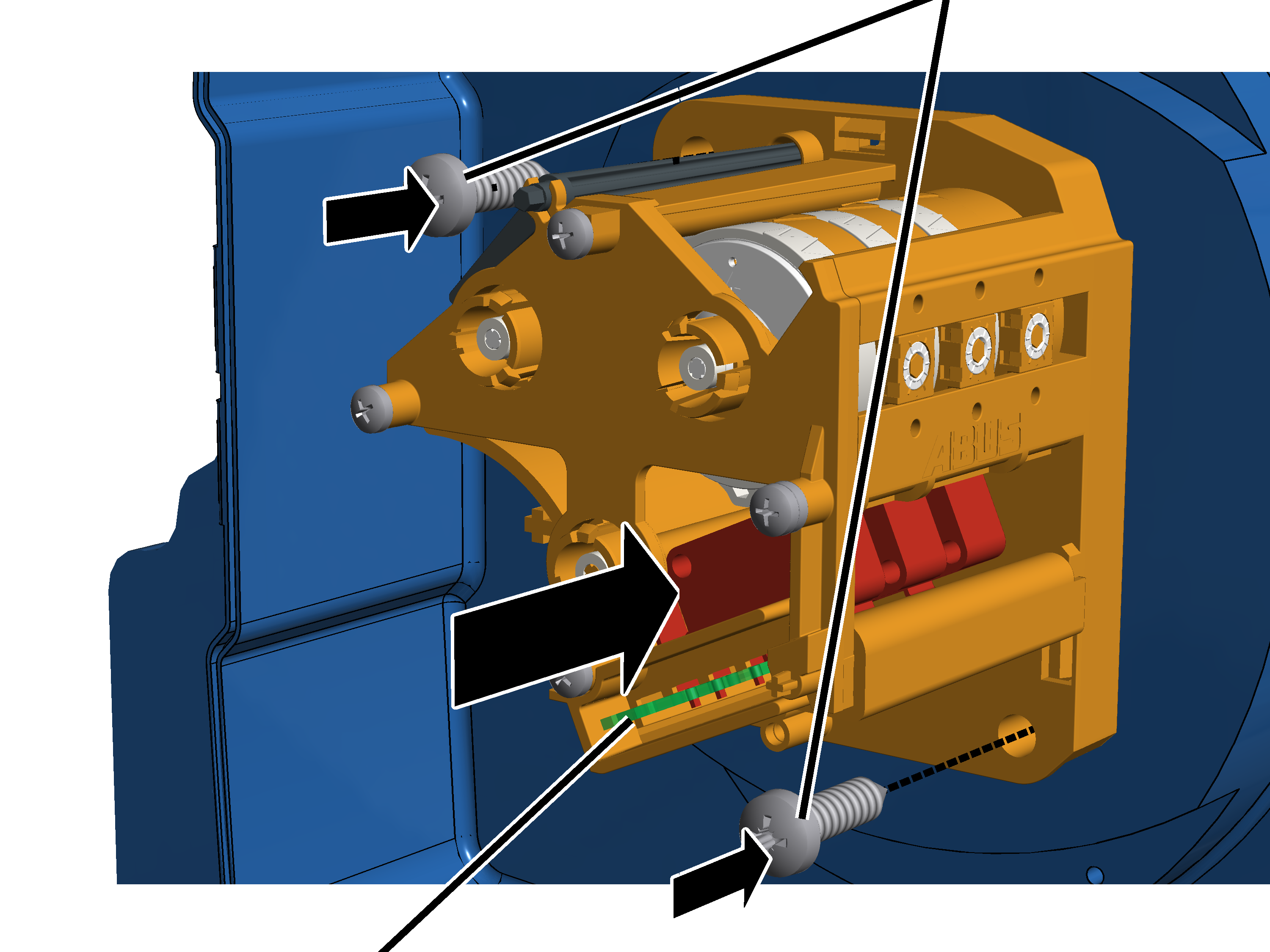
 Open the hoist limit switch housing.
Unscrew and remove screws
(2x).
Pull off the hoist limit
switch.
Leave the shaft of the hoist
limit switch in the same position, and do not turn it.
This makes adjusting the hoist limit switch after replacing the wire rope in many cases unnecessary.
Secure the hoist limit switch to ensure it does not
fall down or hang from the connection cables.
|
|
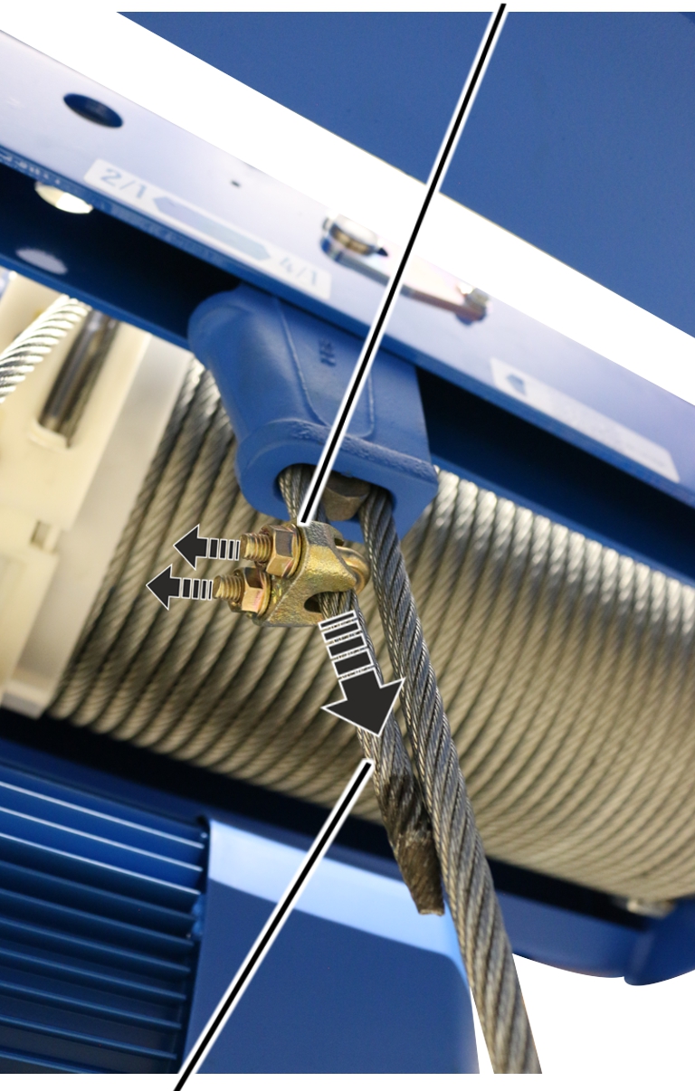
Dead end rope grip |
|
| |
|
End of the wire rope |
|
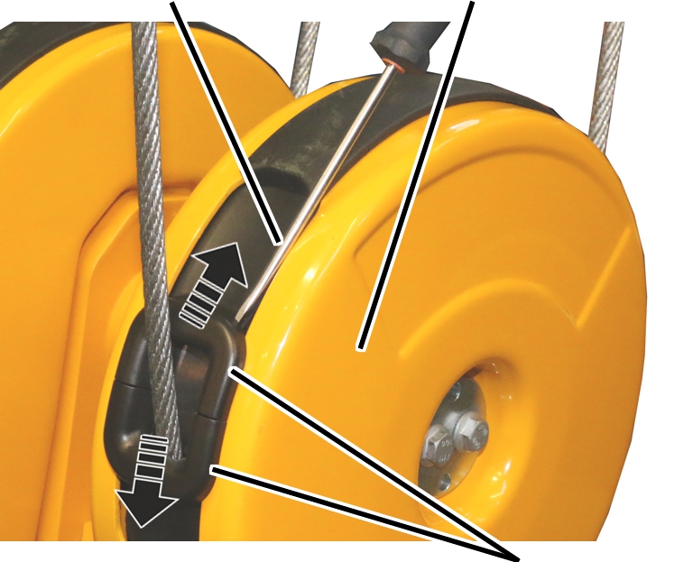
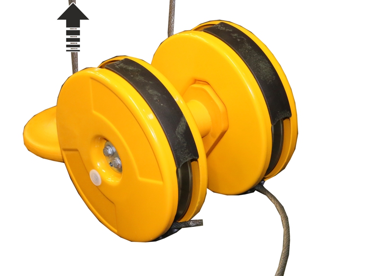
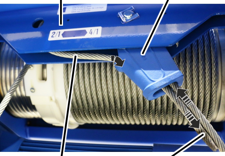
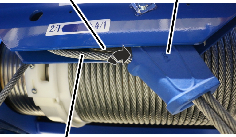
Release the dead end rope grip.
Pull the dead end rope grip from
the end of the wire rope.
If the rope socket or the rope wedge are damaged, they must be replaced.
|
| |
|
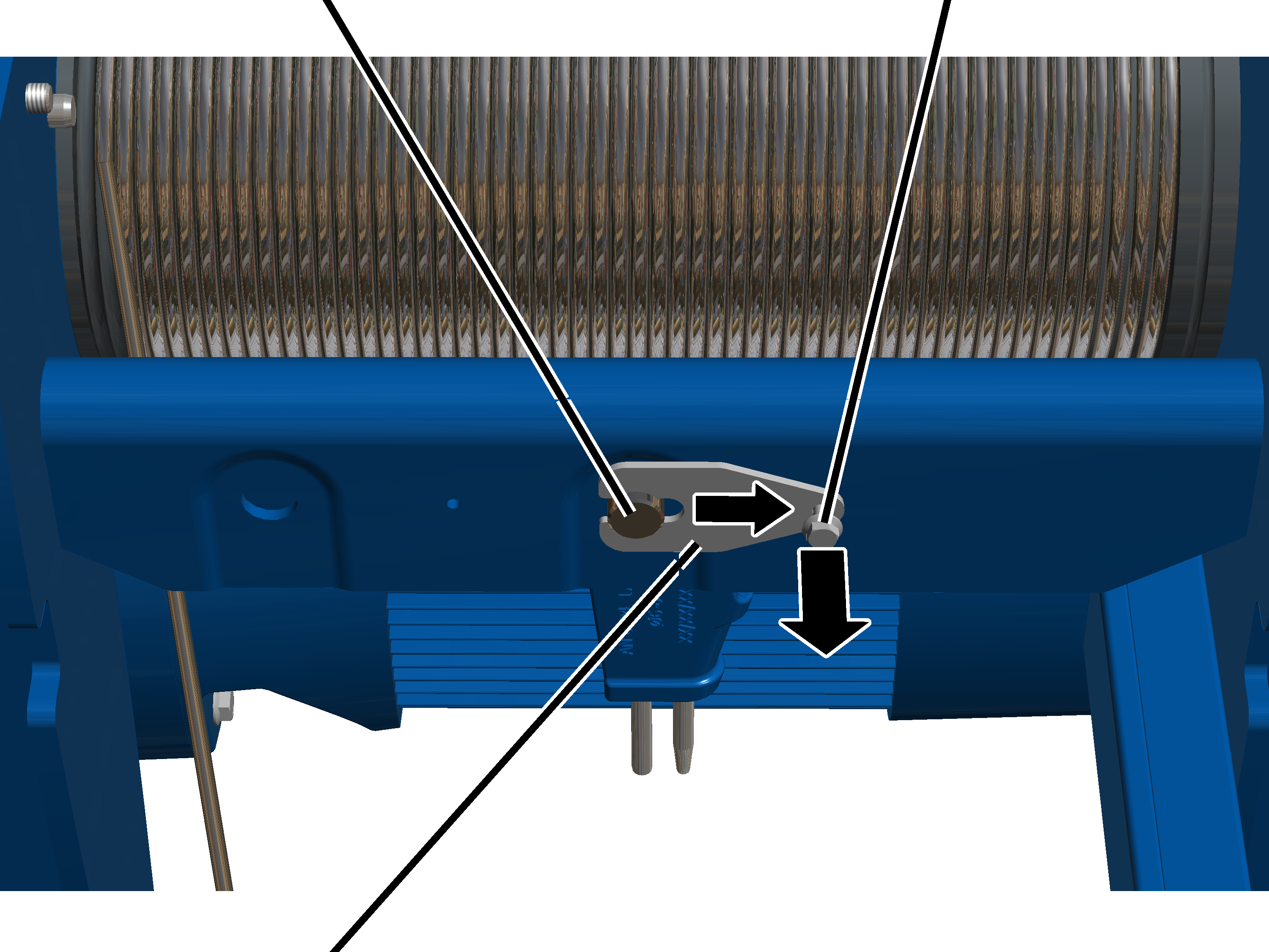
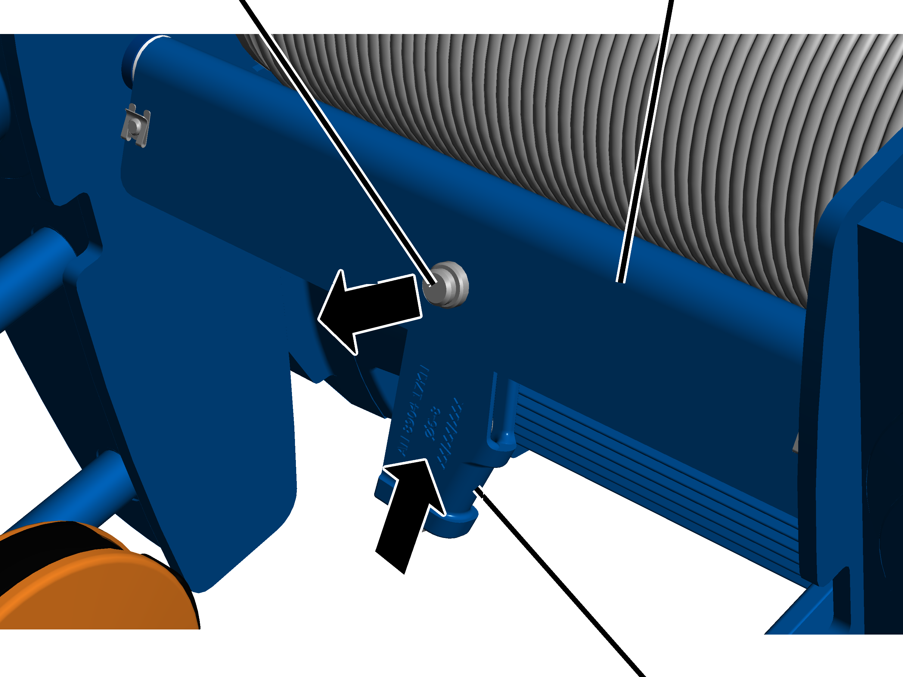
Bolt |
SL safety clip |
Pull off the SL safety clip from the bolt on the
fixed point crosshead.
|
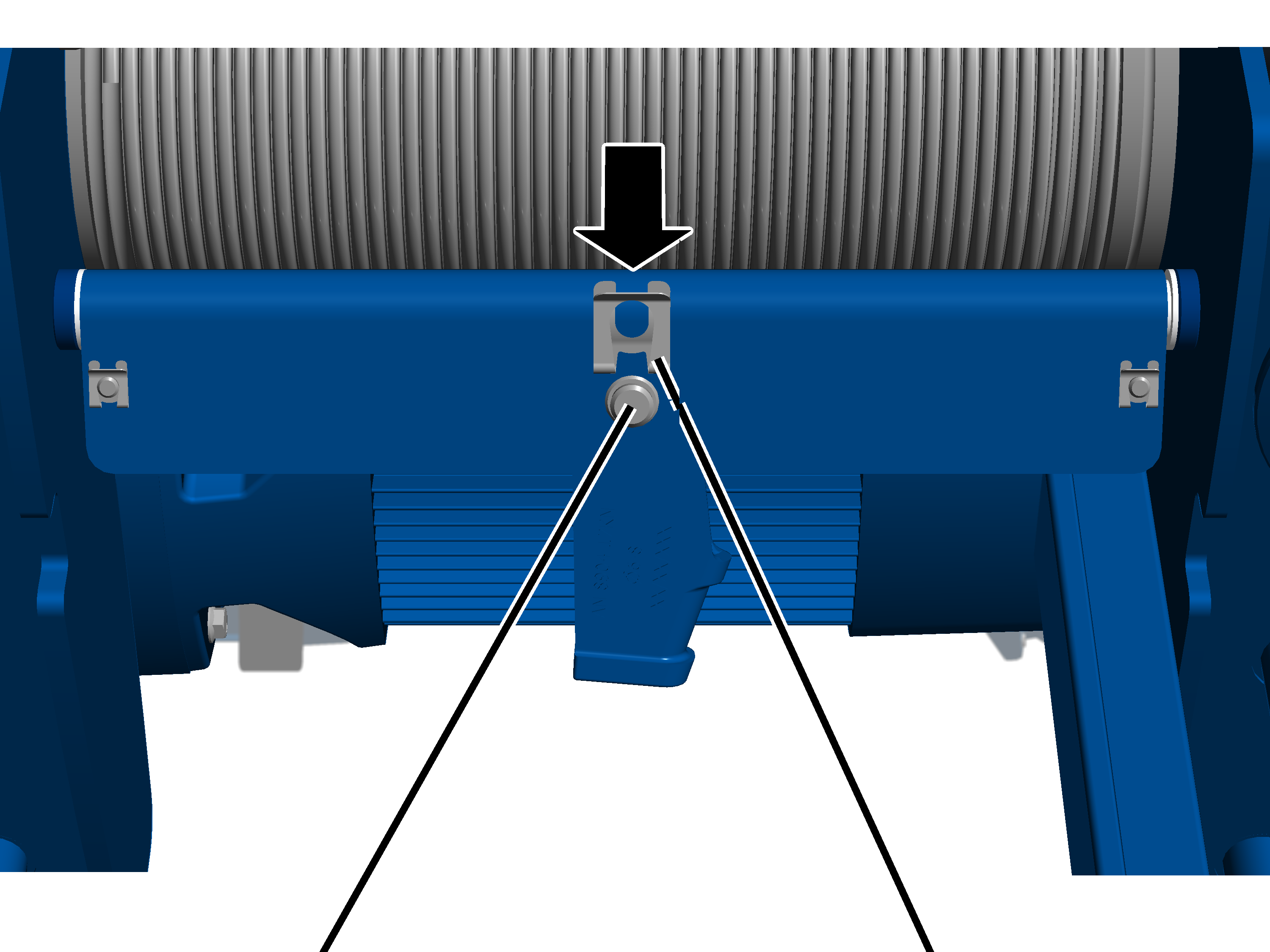
Bolt |
Fixed point crosshead |
|
| |
|
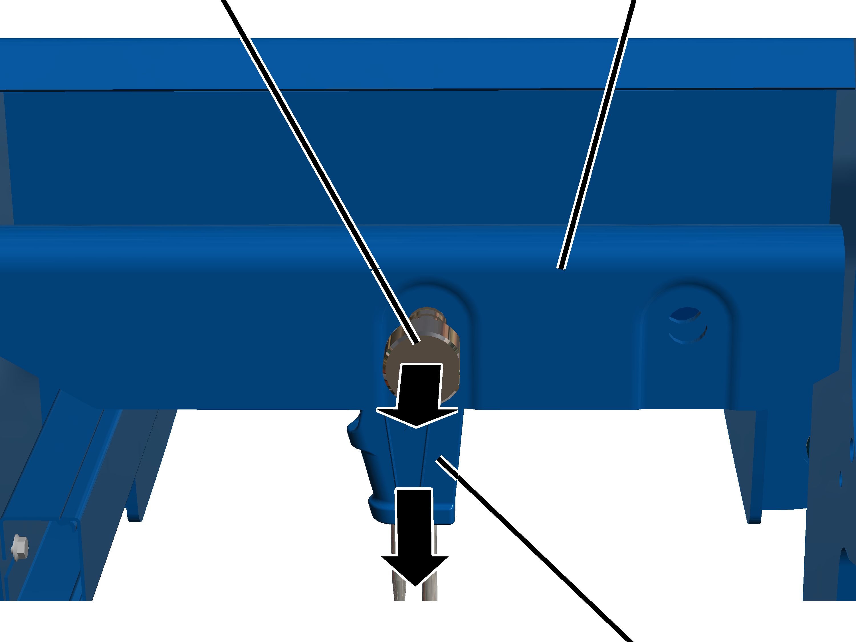
|
Rope socket with rope wedge |
Push the bolt out of the fixed point
crosshead.
Pull the rope socket out of the
fixed point crosshead.
If the rope socket or the rope wedge are damaged, they must be replaced.
|
Measurement bolt |
Rib screw |
|
| |
|
Mount |
|
Slide the mount from the
measurement bolt.
|
Measurement bolt |
Rib screw |
|
| |
|
|
Rope socket |
Pull the measurement bolt out of the
fixed point crosshead and the rope socket.
Pull the rope socket out of the
fixed point crosshead.
|
|
Rope socket |
|
| |
|
Rope wedge |
Wire rope |
Drive the rope wedge out of the rope socket
and take it out.
Disassemble the rope socket.
Turn the rope socket over and
knock out the rope wedge from above.
The rope wedge can in this way be more easily knocked out of the rope socket.
|
Fixed point crosshead |
Rope socket |
|
| |
|
Loop |
End of the wire rope |
Push the end of the wire rope out of the
rope socket.
|
Fixed point crosshead |
Rope socket |
|
| |
|
|
Wire rope |
Pull the wire rope out of the rope
socket.
ABUS recommends replacing the rope guard together with the wire rope.
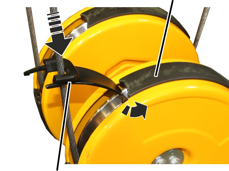
On all openings on the bottom block:
|
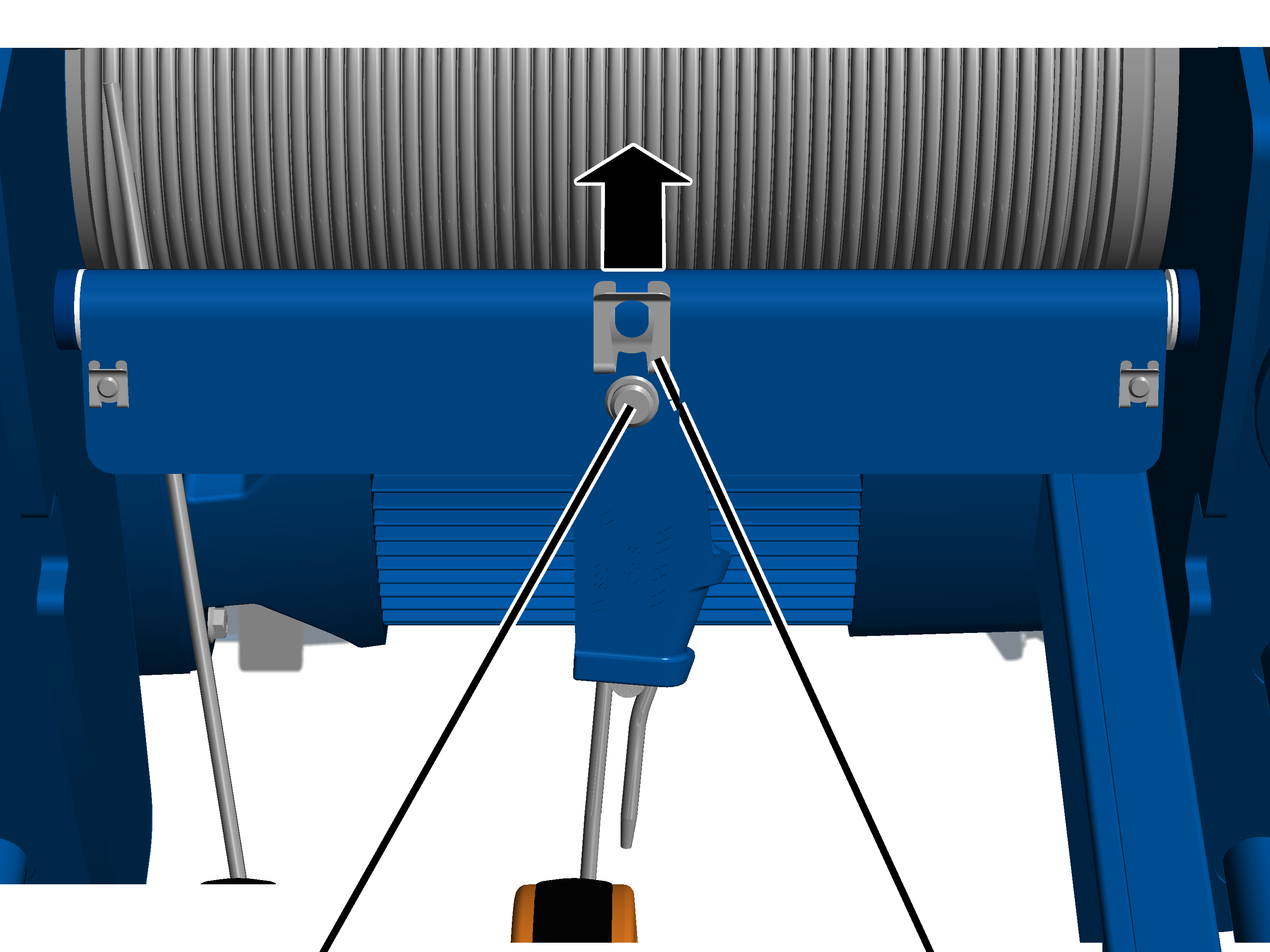
Screwdriver |
Bottom block cover |
|
| |
|
|
Rope guard |
Insert the screwdriver laterally
between the rope guard and bottom block cover as shown in the figure.
Use the screwdriver to unhook
the load hooks on the left and right of the rope guard at the same time.
Pull the rope guard (2x) apart
and remove it from the bottom block.
|
|
Fit the bottom block.
Pull the wire rope out of the
bottom block.
|
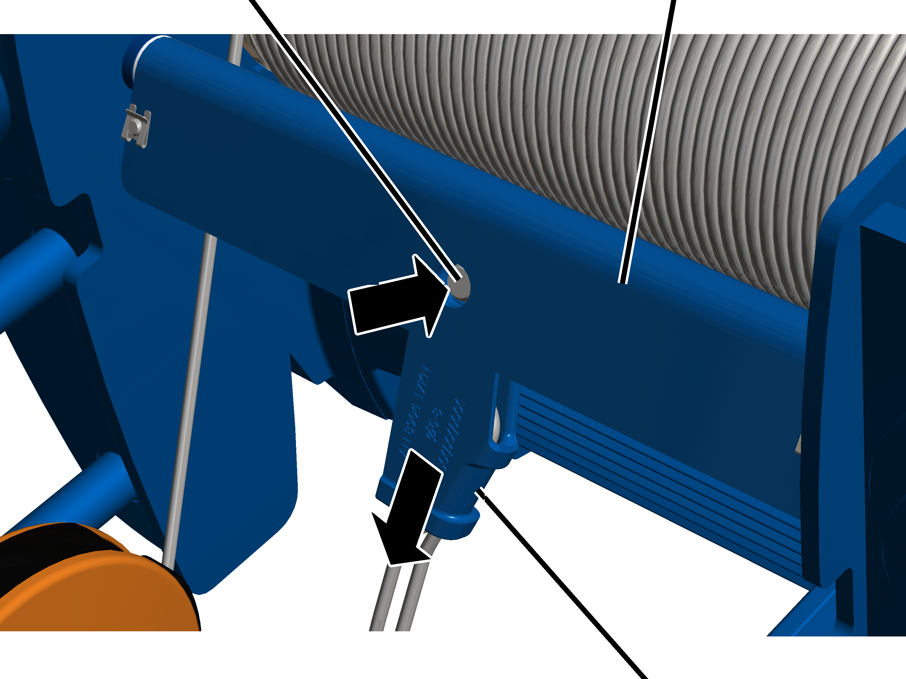
Self-tapping screw |
|
|
| |
|
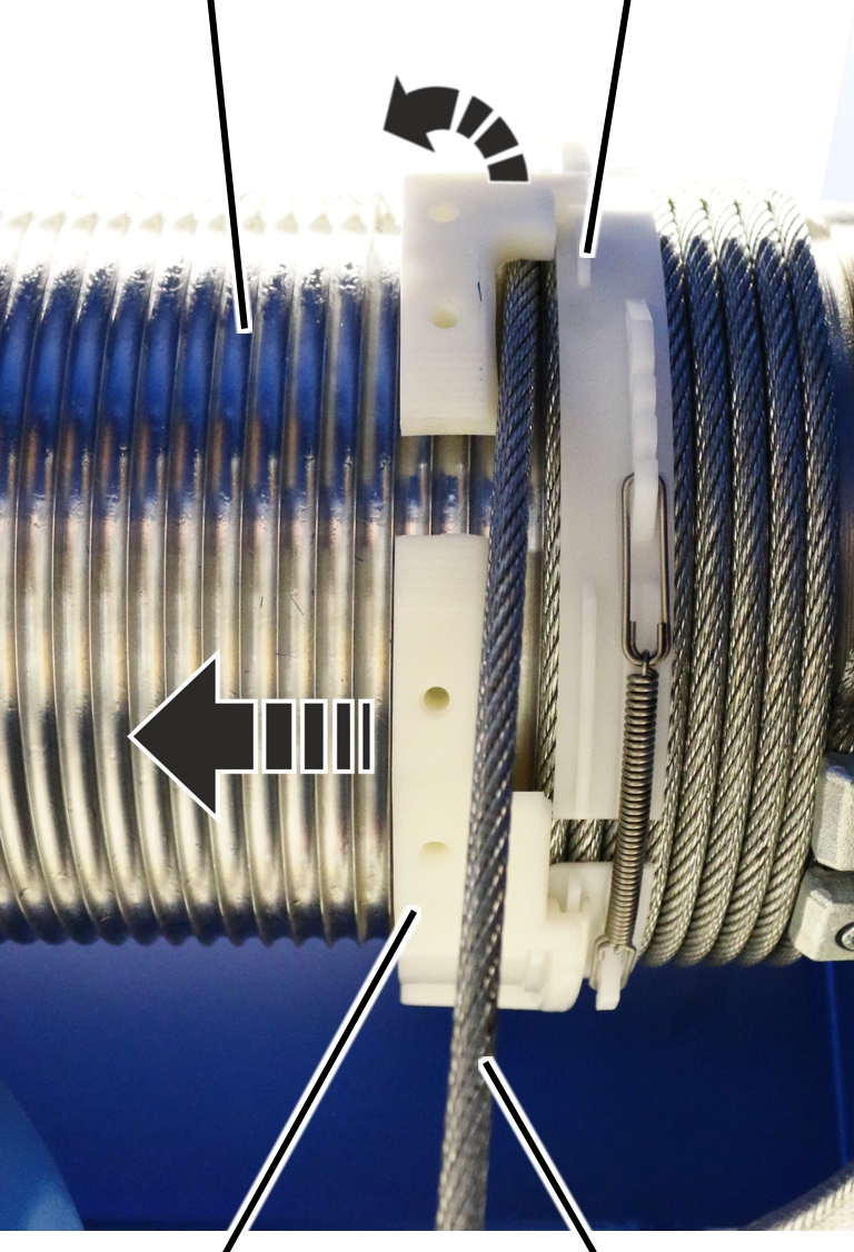
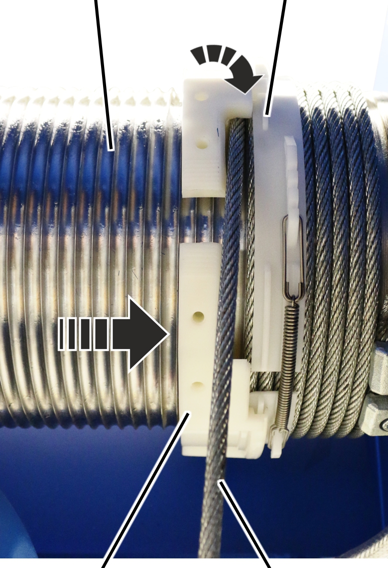
Rope guide ring |
Rope guide runner |
Allow the wire rope to run off the cable
drum using the motor.
Several wire rope windings should remain on the cable drum.
Unscrew the rope guide
runner.
|
| |
|
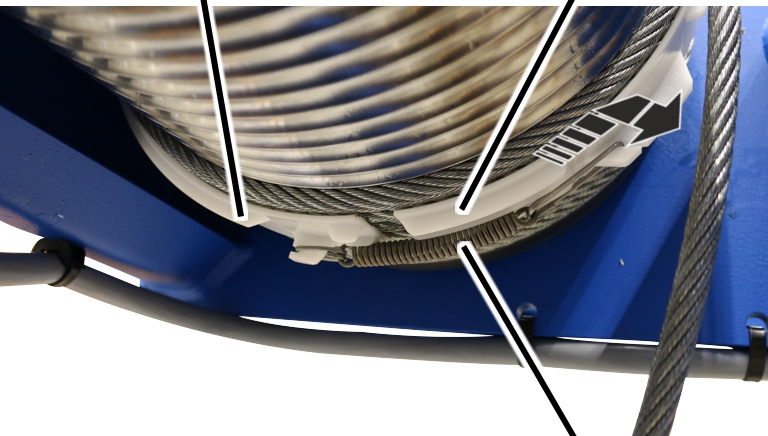
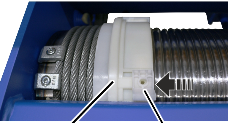
Rope guide ring |
Rope guide runner |
Push the rope guide runner away to one side
of the rope guide ring.
● The rope guide ring can now be turned freely on the cable drum.
|
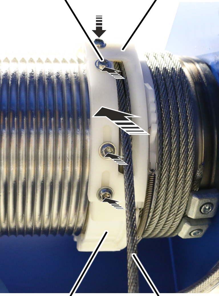
Hexagon head screw |
Joining element |
|
| |
|
Wire rope |
Rope guide ring |
Turn the rope guide ring so that the screws (4x)
are easily accessible (e.g. upwards).
Loosen screws (4x).
Remove the joining element and
unthread it from the wire rope.
|
Cable drum |
Ridge |
|
| |
|
Cable guide |
Wire rope |
Force the rope guide ring apart and pull it
inwards and off the cable drum.
|
Ridge |
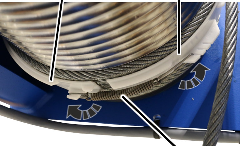
Rope tension ring |
|
| |
|
|
Tension spring |
Remove the tension spring from the rope tension
ring.
Force the rope tension ring
apart and pull it inwards and off the cable drum.
● The cable guide has now been disassembled. The wire rope is now lying loose on the cable drum.
|
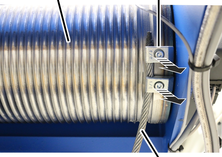
Cable drum |
End clamps |
|
| |
|
|
Wire rope |
Allow the wire rope to run off the cable drum
using the motor.
Release the end clamps (2x).
Completely remove the wire rope
from the cable drum.
|
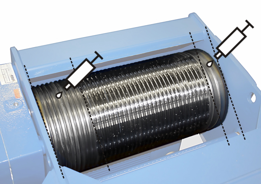
|
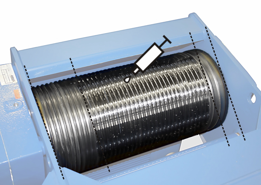
Lubricate the cable drum from
the start to about the 8th or 10th turn.
Lubricate the cable drum behind
the last turn.
Lubricant: “Molykote PG-75”. For details, see Lubricants.
|
|
Lubricate the cable drum behind
the 8th/10th turn up to the last turn.
Lubricant: “Chainlife S”. For details, see Lubricants.
|
|
Roll out the wire rope without twisting it! The wire rope will bend and become damaged if it is unrolled incorrectly. Do not pull the wire rope upwards away from a horizontally-lying ring. Unroll the ring so it is vertically upright instead, and allow the wire rope to run onto the cable drum in the same direction as it was rolled onto the ring. |
|
Cable drum |
Fillister-head screw |
|
| |
|
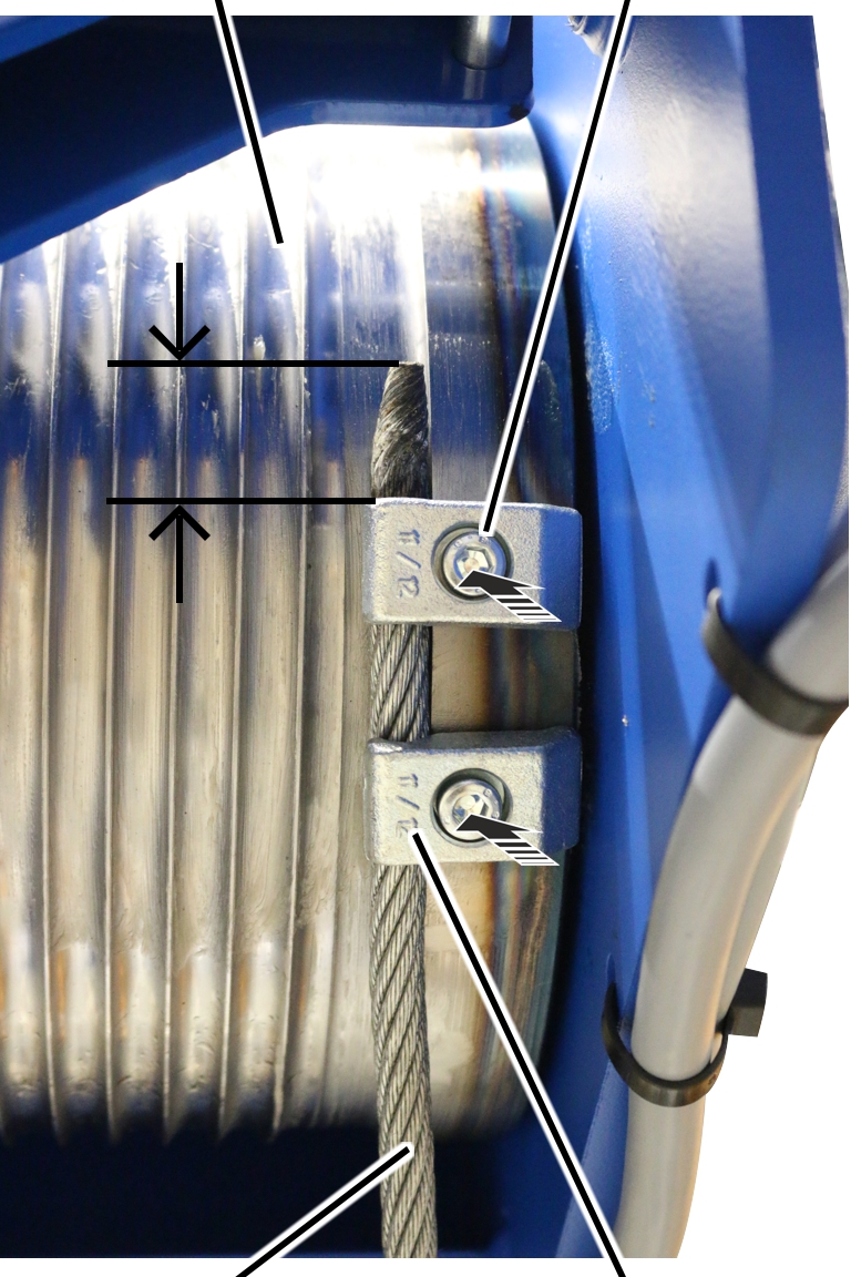
Wire rope |
End clamp |
Unroll the wire rope without twisting
it.
Thoroughly clean the
fillister-head screws of the end clamps.
The fillister-head screws were previously bolted with a thread lock coating or a thread lock. The residues must be completely removed before the fillister-head screw may be used again.
The thread lock coating as well as the thread lock are single-use only.
Push the wire rope under the end
clamps far enough that the rope protrusion is about 30 mm.
Tighten the end clamps (2x) with
fillister-head screws and secure with (medium strength) thread lock.
|
Size |
Fillister-head screw |
Number |
Tightening torque |
|
GM 800 |
M6x16 |
2 |
10 Nm |
|
GM 1000 |
M8x20 |
2 |
25 Nm |
|
GM 2000 |
M8x20 |
2 |
25 Nm |
|
GM 3000 |
M8x20 |
2 |
25 Nm |
|
Ridge |
|
|
| |
|
Cable drum |
Rope tension ring |
Turn the rope tension ring so that the ridge is
facing the hoisting gear.
Force the rope tension ring
apart and guide it over the wire rope on the cable drum.
|
Ridge |
Rope tension ring |
|
| |
|
|
Tension spring |
|
Cable drum |
Ridge |
|
| |
|
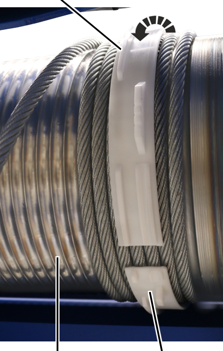
Rope guide ring |
Wire rope |
Grease the groove of the rope
guide ring.
Lubricant: “Molykote PG-75”. For details, see Lubricants.
Force the rope guide ring apart and push it
over the cable drum.
Place the rope guide ring with
the groove into the ridge on the rope tension ring.
Place the rope guide ring with
the threaded segments into the free section of the cable drum.
Check that both ends of the rope
guide ring lie in the same groove of the cable drum.
The ends of the rope guide ring must be aligned.
|
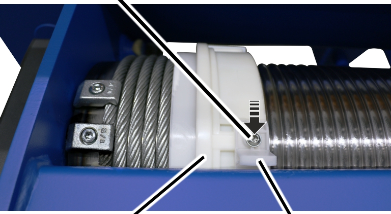
Self-tapping screw |
Joining element |
|
| |
|
Rope guide ring |
Wire rope |
Thread the
joining element onto the wire rope.
Push the joining element upwards
and place it onto the rope guide ring.
Tighten the joining element with
self-tapping screws M6x16 (4x). 5 Nm.
When doing this, first secure the upper screws which do not lie in the elongated hole.
|
| |
|
Rope guide ring |
Rope guide runner |
Put the rope guide runner on the drum housing
and push it laterally into the rope guide ring.
|
Self-tapping screw |
|
|
| |
|
Rope guide ring |
Rope guide runner |
Screw on the rope guide runner with the
self-tapping screw M6x16. 5 Nm.
|
| |
|
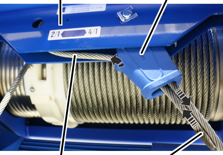
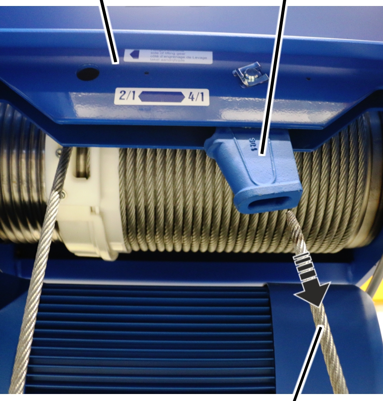
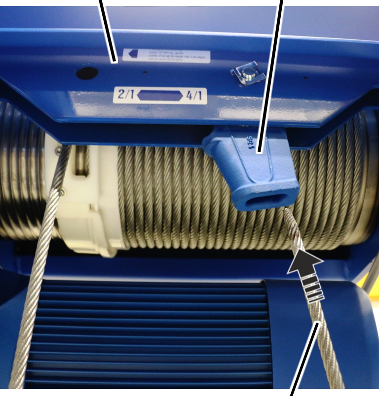
Reeving 2/1 |
Reeving 4/1 |
 For reeving 2/1: Pull the wire
rope from the cable drum and through the bottom block, without twisting it.
For reeving 2/1: Pull the wire
rope from the cable drum and through the bottom block, without twisting it.
 For reeving 4/1: Pull the wire
rope from the cable drum and through the bottom block, without twisting it, and
through the deflection roller and once again through the bottom block.
For reeving 4/1: Pull the wire
rope from the cable drum and through the bottom block, without twisting it, and
through the deflection roller and once again through the bottom block.
|
Bolt |
Fixed point crosshead |
|
| |
|
|
Rope socket |
Push the rope socket into the fixed point
crosshead.
Note the marking on the fixed point crosshead.
Push the bolt through the fixed
point crosshead and the rope socket.
|
| |
|
Bolt |
SL safety clip |
Push the SL safety clip onto the bolt.
|
Measurement bolt |
Fixed point crosshead |
|
| |
|
|
Rope socket |
Push the rope socket into the fixed
point crosshead.
Note the marking on the fixed point crosshead.
Push the measurement bolt
through the fixed point crosshead and the rope socket.
The arrow on the measurement bolt must point downward!
|
Measurement bolt |
Rib screw | |
|
| ||
|
Mount |
| |
Slide the mount onto the measurement
bolt.
The mount must allow itself to be inserted into the groove of the measurement bolt without tension.
The measurement bolt should not have any pretension!
Screw on the mount with the rib
screw M6x12. 19 Nm.
|
Fixed point crosshead |
Rope socket | |
|
| ||
|
|
End of the wire rope | |
Check the lubrication of the rope socket and
grease it if necessary.
Lubricant: “High temperature paste PBC 1574”. For details, see Lubricants.
Push the end of the wire rope into the rope
socket from below.
|
Rope socket |
Fixed point crosshead |
|
| |
|
Loop |
End of the wire rope |
Push the end of the wire rope into the rope
socket from above so that a loop forms.
The end of the wire rope protrudes below about 150 mm out of the rope socket.
|
Rope wedge |
Rope socket |
|
| |
|
Loop |
|
Place the rope wedge in the loop.
|
|
Rope socket |
|
| |
|
Rope wedge |
Wire rope |
Give the wire rope a jolting tug.
● The rope wedge slips into the rope socket and the wire rope is tightly clamped.
|
|
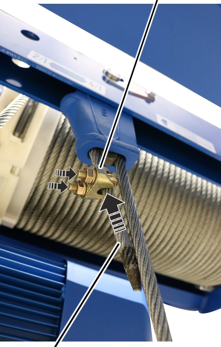
Dead end rope grip |
|
| |
|
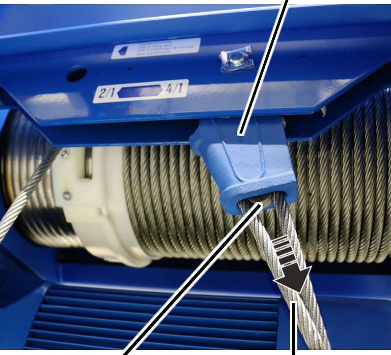
End of the wire rope |
|
Push the dead end rope grip over the end of the
wire rope.
The dead end rope grip lies about 30 mm below the rope socket.
Screw the dead end rope grip
tight.
|
Size |
Rib nut |
Tightening torque |
|
GM 800 |
M6 |
5 Nm |
|
GM 1000 |
M8 |
10 Nm |
|
GM 2000 |
M8 |
10 Nm |
|
GM 3000 |
M12 |
10 Nm |
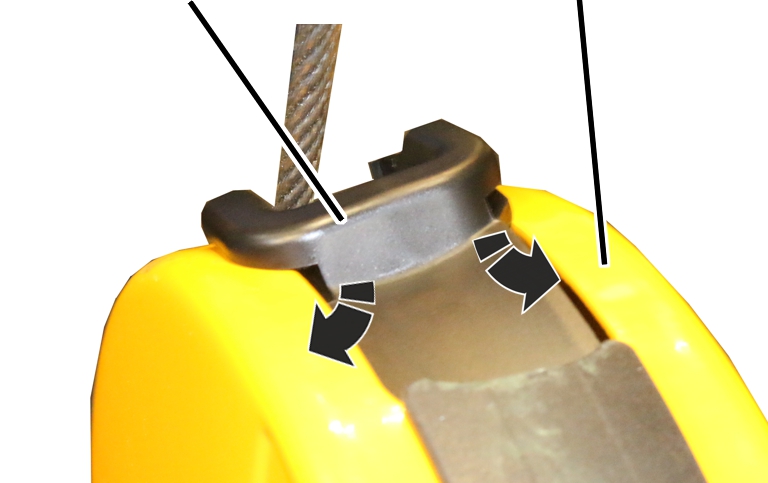
On all openings on the bottom block:
|
|
Connecting profile |
|
| |
|
Rope guard |
|
Hold the rope guard on the wire
rope as shown in the figure.
Push the rope guard down along
the wire rope with the front fork and bring the rear end under the connecting
profile.
|
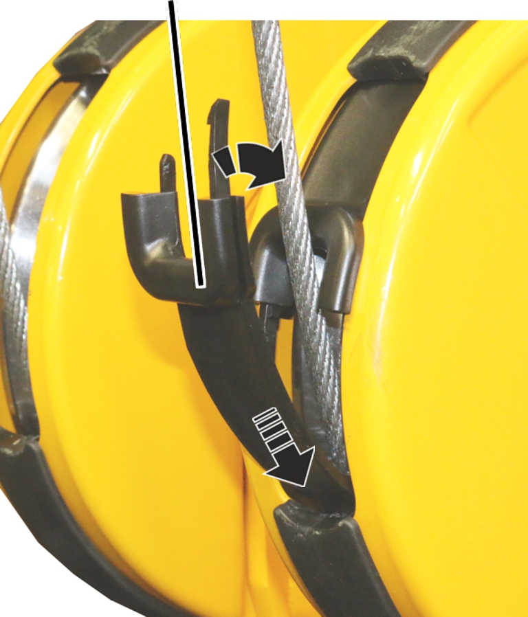
Rope guard |
Bottom block cover |
|
| |
First push the rope guard on the
side with the short bracket into the bottom block cover.
Then push the rope guard on the
side with the long bracket into the bottom block cover.
|
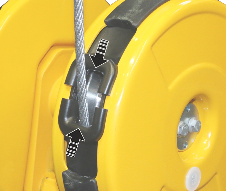
Rope guard |
|
|
| |
Push the second rope guard at
the bottom into the connecting profile.
Push the rope guard downwards
behind the connecting profile and attach it above on the wire rope.
First push the rope guard on the
side with the short bracket into the bottom block cover.
Then push the rope guard on the
side with the long bracket into the bottom block cover.
|
|
Connect the brackets of the rope
guards (2x) and push them together.
● A snapping sound can be heard.
Use the motor to wind up the
wire rope completely.
If ABUControl is installed for the wire rope hoist, refer to the product manual “ABUControl”, section “Exchanging the wire rope” to conclude the rope change.
Further steps are then described in this product manual.
Move the load hooks to the
position you noted previously.
|
Shaft |
Bearing flange |
|
| |
Open the housing cover of the
hoist limit switch enclosure on the cable drum.
Rotate the shaft of the gear
limit switch so that it matches the elongated hole in the bearing flange of the
cable drum.
|
|
Plastic screws B6, 3x25 |
|
| |
|
Cam switch PCB |
|
Insert the gear limit switch
with the shaft in the elongated hole on the bearing flange and guide it onto the
two pins.
Screw the gear limit switch
tight with the plastic screws B6.3x25. 2.5 Nm. 2.5 Nm.
Plug
in the connector of the connection cable on the cam switch PCB.
If the switching points have moved:
Normally, the adjustment of the hoist limit switch after replacing the wire rope can in many cases be omitted, since the position of the load hook was previously measured and then travelled to again. In special cases (e.g. if the wire rope is severely damaged or has been incorrectly rolled onto the cable drum), the switching points may need to be readjusted.
Reset switching points for the
bottom hoist limiter, the top hoist limiter and the backup limiter.
With ABUS electrics 3 with contactor control: see product manual “ABUS gear limit switch”.
With ABUS electrics 3 with ABULiner: see product manual “Frequency converter control of the lifting speed for ABUS electrics 3”.
|
|
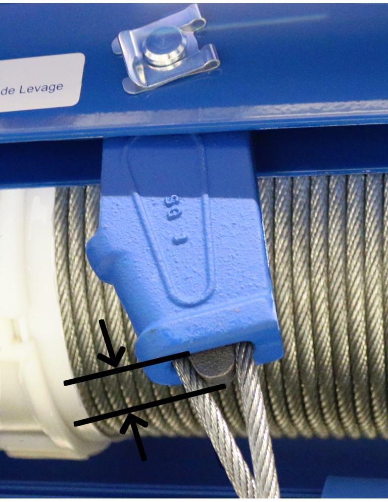
Suspend the load from the load hooks, raise it and
load the wire rope this way.
Measure the rope wedge
protrusion and check whether the dimensions specified in the table have been
complied with.
|
Size |
Rope wedge protrusion when the wire rope hoist is new |
Maximum rope wedge protrusion |
Minimum rope wedge protrusion |
|
GM 800 |
18 mm |
19 mm |
18 mm |
|
GM 1000 |
3 mm |
4 mm |
3 mm |
|
GM 2000 |
0 mm |
2 mm |
0 mm |
|
GM 3000 |
16 mm |
18 mm |
16 mm |