|

|
Danger to persons due to defective gear limit
switch!
If a gear limit switch is disassembled and
repaired, it might no longer function properly. This could cause the load
to fall, killing or injuring people.
Replace defective gear limit switches only as a
complete assembly! |
Installing the
gear limit switch
|
Shaft |
Bearing
flange |
|
|
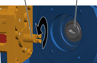
 Open the housing cover of the
hoist limit switch enclosure on the cable drum.
Open the housing cover of the
hoist limit switch enclosure on the cable drum.
Rotate the shaft of the gear
limit switch so that it matches the elongated hole in the bearing flange of the
cable drum.
|
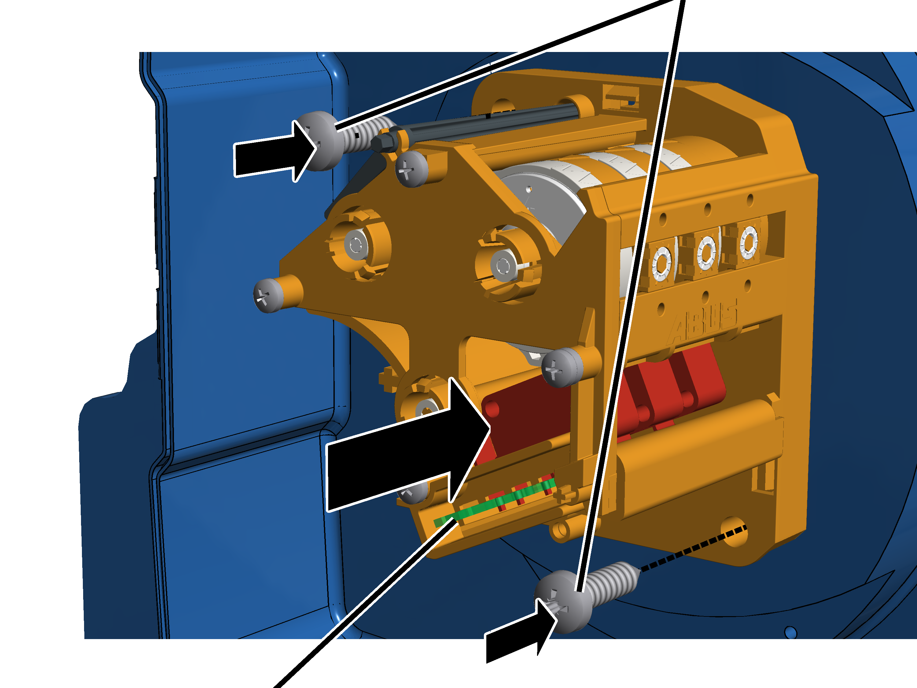
Plastic screws B6, 3x25 |
|
|
|
Cam
switch PCB |
|
Insert the gear limit switch
with the shaft in the elongated hole on the bearing flange and guide it onto the
two pins.
Screw the gear limit switch
tight with the plastic screws B6, 3x25. 3 Nm.
Connecting the
gear limit switch
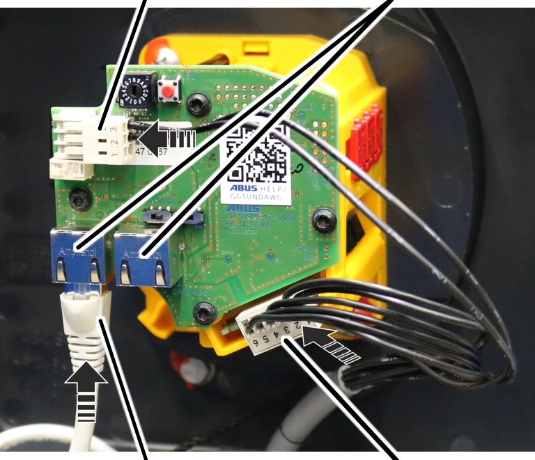
Plug in the connector of the
connection cable on the cam switch PCB.
Only with absolute rotary
encoder
Connecting the
absolute rotary encoder
|
Connector of the connection cable on the cam switch
PCB |
Connections for CAN bus network and Modbus network |
|
|
|
Connection cable |
Connector of the connection cable on the cam switch
PCB |
Insert the RJ45 connection cable
for the CAN bus network or Modbus network.
Both connections on the circuit board of the absolute rotary
encoder are suitable for a CAN bus network (ABUControl Comfort) as well as a
Modbus network (ABUControl Basic). The bus system that is used is recognised
automatically.
The second port can be used to connect an additional CAN bus
device or Modbus device.
The second connector of the
connection cable for the cam switch PCB is inserted in the white pin multipoint
connector above the connections for the CAN bus network or Modbus network.
Close the housing cover.
Set all switching points. See ABUS
electrics 3: Setting the switching point for the bottom hoist limiter and ABUS
electrics 3: Setting switching points for backup limiter and top hoist
limiter.