Lower the load hook to the
desired lowest hook position.
Lower the load hook to the
desired lowest hook position.
This section only applies to cranes with ABUS electrics 3. For cranes with ABUControl: see the ABUControl product manual.
The wire rope hoist has a gear limit switch with three switching points. The backup limiter and the top hoist limiter are set at the factory. The bottom hoist limiter must be set on site.
Lower the load hook to the
desired lowest hook position.
─ The load hook should not touch the floor of the building.
─ The wire rope should not be slack.
─ A certain minimum clearance must be maintained between the cable guide and the drum housing. This clearance is determined in the next work step.
─ The hook path (distance between the highest hook position [= hook headroom, dimension C] and the lowest hook position) must not be greater than is specified on the type plate.
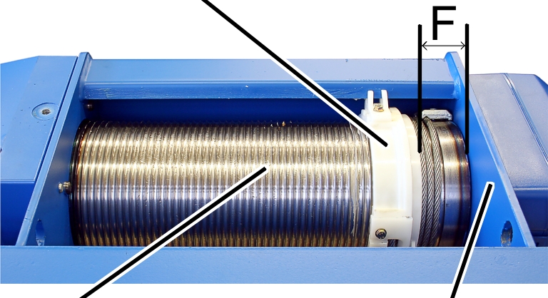
|
Cable guide |
|
|
| |
|
Cable drum |
Drum housing |
Measure the distance 'F' between
the cable guide and the drum housing and compare this with the table.
|
Wire rope hoist |
Type |
Reeving |
Distance ‘F’ |
|
GM 800 |
E, D, DA |
4/1 |
42 ± 2 |
|
GM 1000 |
E, D, |
4/1 2/1 |
56 ± 2 |
|
GM 2000 |
E, D, |
4/1 2/1 |
59 ± 2.5 |
|
GM 3000 |
E, D, |
4/1 2/1 |
73 ± 2.5 |
|
GM 5000 |
E, D, DA, DQA |
4/1 2/1 |
87.5 ± 3 |
|
GM 5000 |
D |
4/2 |
73 ± 2.5 |
|
GM 5000 |
Z |
4/2 8/2 |
87.5 ± 3 |
|
GM 6000 |
E, D, DA, DQA |
4/1 2/1 |
102 ± 3 |
|
GM 6000 |
Z |
4/2 8/2 |
102 ± 3 |
|
GM 7000 |
D, DA, |
2/1 4/1 6/1 |
131 ± 4 |
|
GM 7000 |
D |
4/2 8/2 |
87 ± 3 |
|
GM 7000 |
Z, ZA |
4/2 6/2 8/2 10/2 |
131 ± 4 |
|
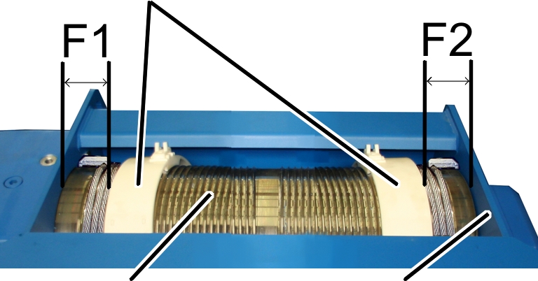
Cable guide |
|
|
| |
|
Cable drum |
Drum housing |
Measure the distances 'F1' and
‘F2’ between the cable guides and the drum housing and compare these with the
table.
|
Wire rope hoist |
Distance ‘F1’ |
Distance ‘F2’ |
|
GM 5000 - D |
80 ± 3 |
76 ± 3 |
|
GM 7000 - D |
84 ± 3 |
87 ± 3 |
|
|
Danger to persons from load drop! The cable can be torn from the cable drum if the distances ‘F’ or ‘F1’ and ‘F2’ are not met. This could cause the load to fall, killing or injuring people. The distance guarantees that there is always enough wire rope wound onto the cable drum. Always maintain ‘F’ or ‘F1’ and ‘F2’. |
If necessary, raise the load
hook until the distance 'F' or ‘F1’ or ‘F2’ is achieved.
● The lowest hook position of the load hook has now been determined. From this point, the braking distance will now be subtracted.
|
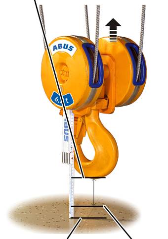
Lowest
hook position |
|
|
| |
|
Floor of building |
Lowest hook position |
Raise the load hook until it is
500 mm above the lowest hook position.
|
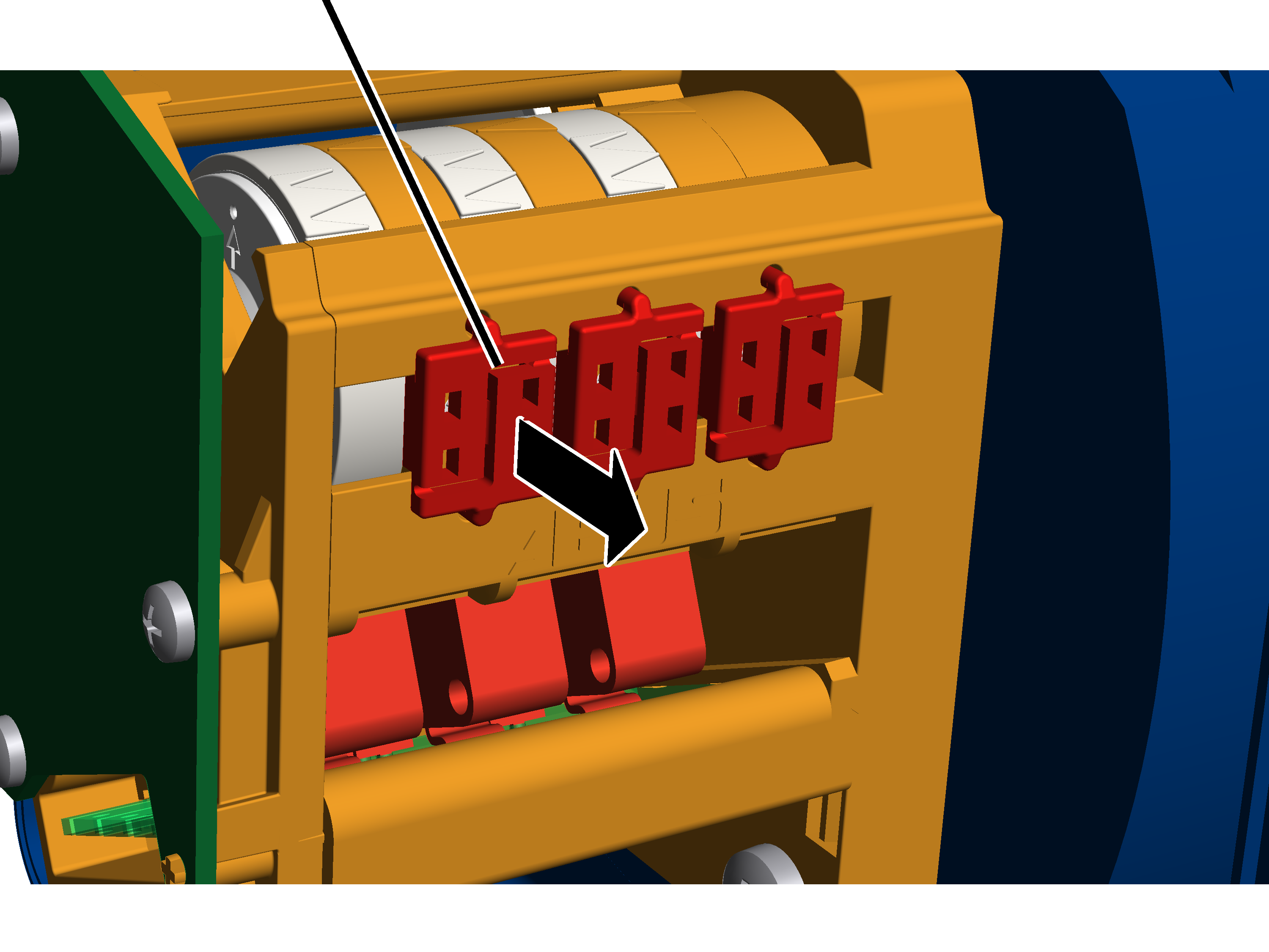
Seal |
|
|
| |
Take off the housing cover of
the hoist limit switch enclosure on the cable drum.
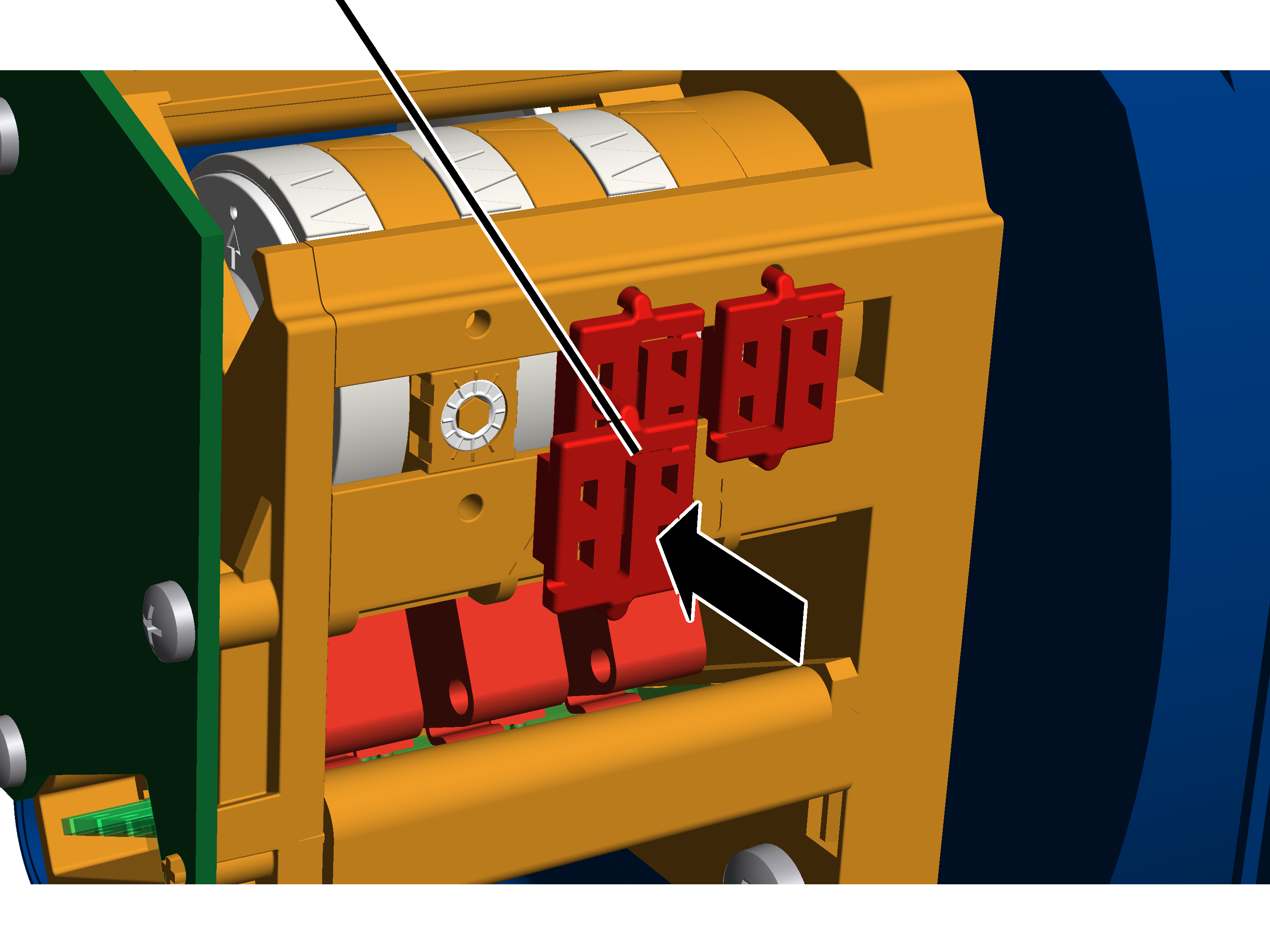
Press the seal apart in the
centre with a screwdriver and remove it.
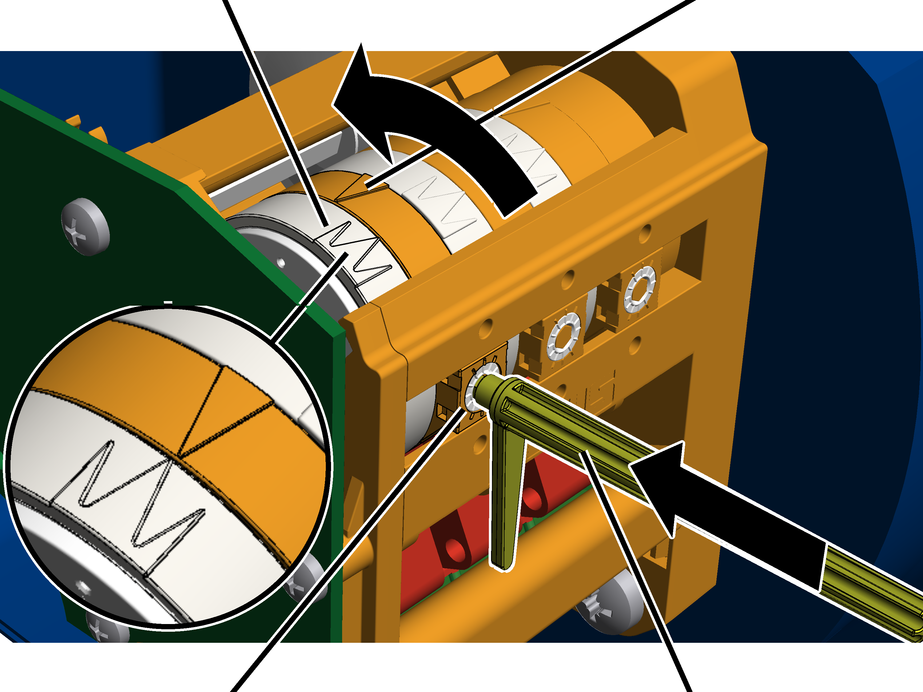
The bottom hoist limiter is set with the left adjusting screw.
|
White pointer of cam ring |
Orange pointer |
|
| |
|
Left adjusting screw |
Adjusting key |
Remove
the adjusting key. It is fastened on two mounts on the gear limit
switch.
Alternatively, a hexagon wrench key size 3.0 (ideally with rotary plate) can be used.
An electrically operated screwdriver may NOT be used.
Press the adjusting key into the
adjusting screw. Press it into the adjusting screw with light pressure.
If necessary: Turn the adjusting
screw until the white pointer of the cam ring lies to the right of the orange
pointer. It should be neither to the left of the orange pointer nor exactly on
it.
The middle white arrow shows the exact position of the switching point; the two white arrows to the left and right of it indicate the start and end of the switching phase (switching hysteresis).
If necessary: Turn the adjusting
screw until the white pointer of the cam ring lies to the right of the orange
pointer. Continue turning until the white pointer lies exactly on the orange
pointer and a clicking sound is audible.
─ Turning to the right shifts the switching point downward.
─ Turning to the left shifts the switching point upward.
Raise the load hook.
Lower the load hook at both slow
and fast lifting speed and check whether it halts at the lowest hook
position.
|
Seal |
|
|
| |
Insert the seal on the adjusting
screw and press it in.