Switching point
Backup limiter C1
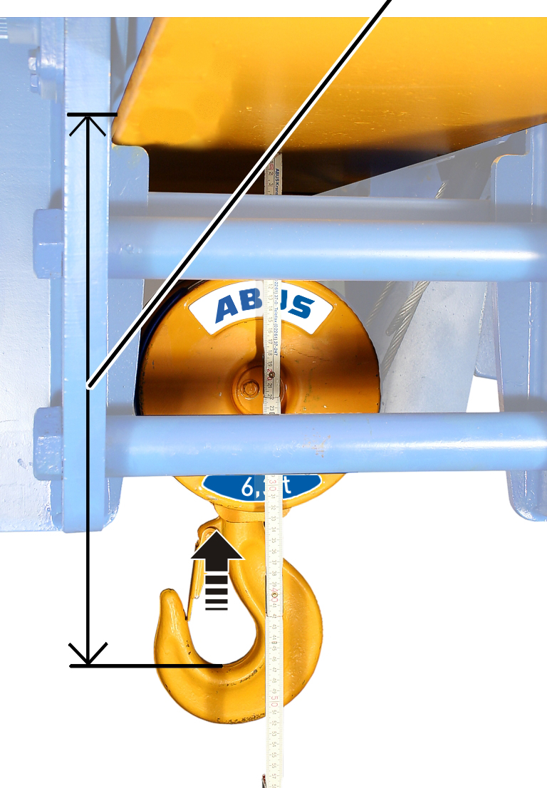
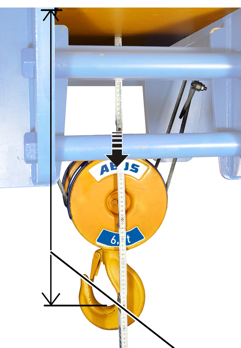
Hook headroom (dimension C)
Top hoist limiter switching point C2
The wire rope hoist has a gear limit switch with three switching points.
The switching points for the top hoist limiter and the backup limiter placed above it are set and sealed at the factory.
If required, (e.g. if the load hook cannot be run right up to the top due to a crosshead), after changing the wire rope or after repairs, the switching point for the top hoist limiter may need to be reset.
|
Switching point |
|
|
| |
|
Hook headroom (dimension C) |
Top hoist limiter switching point C2 |
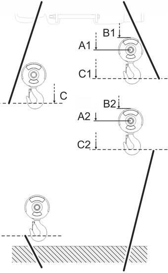
─ The hook headroom (dimension C) is principally the highest position that the load hook may travel to without damaging the wire rope. A certain safety buffer is factored into this.
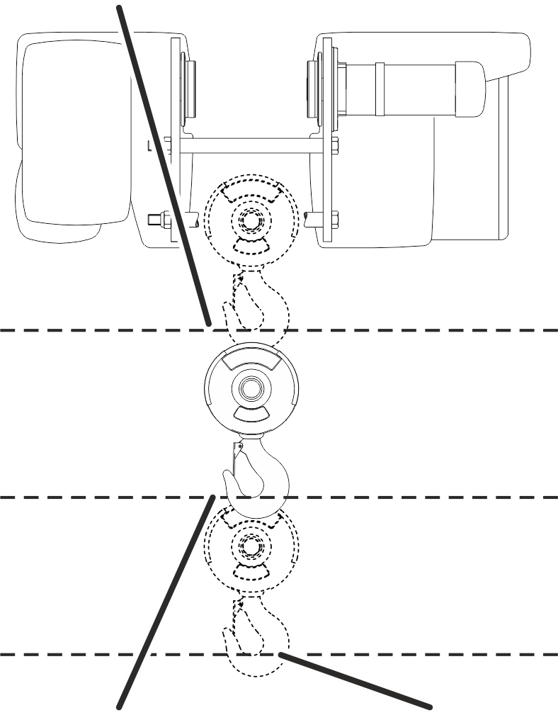
─ The hook headroom (dimension C) is always the distance between the lower edge of the wheel on the wire rope hoist and the inner edge of the load hook.
─ The hook headroom (dimension C) always refers to a standard series load hook. In the case of larger or smaller load hooks, see the wire rope data sheet for details of the hook headroom.
─ The switching point for the backup limiter is designated as C1 and lies slightly above the hook headroom. This is the absolute uppermost position up to which the load hook may move without damaging the wire rope.
─ The switching point for the top hoist limiter is designated as C2 and lies slightly below the hook headroom.
─ Both switching points (C1 and C2) each have two alternative reference edges: A1 and A2 (distance between one of the edges on the wire rope hoist that are easily accessible from below and the axis of the deflection roller on the bottom block), as well as B1 and B2 (distance between one of the edges on the wire rope hoist that are easily accessible from below and the and the upper edge of the bottom block). These additional dimensions can be used as an alternative to the hook headroom and can make measuring easier. They are also independent of the load hook size and can thus be used with smaller or larger load hooks.
|
|
Danger to persons from load drop! In certain situations it can be necessary to enlarge the hook headroom to enable the load hook to brake more quickly, e.g. so that a crosshead cannot crash under the main girder or lifting tackle on the main girder is not broken open, since otherwise the load could fall, killing or injuring people. Always carry out and heed a hazard analysis on site! |
 Select the appropriate reference
edge on the wire rope hoist and on the bottom block from the following
drawing.
Select the appropriate reference
edge on the wire rope hoist and on the bottom block from the following
drawing.
Read the dimensions C1 and C2,
or alternatively A1 and A2 or B1 and B2, from the following table.
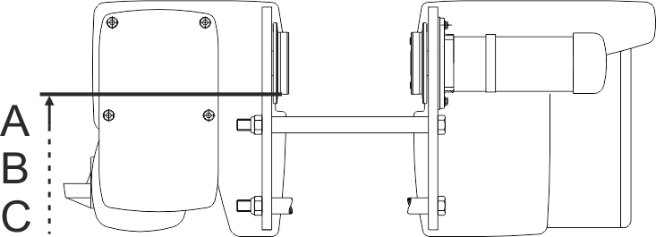
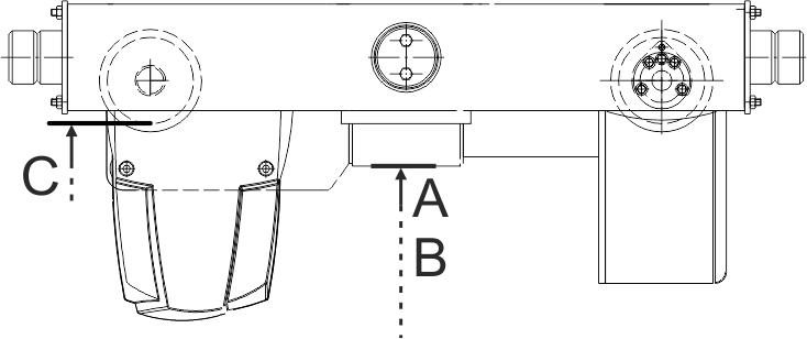
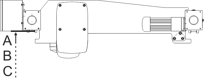
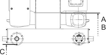
Reference edges on the wire rope hoist according to type:
|
|
Reference edge for dimensions A, B and C on wire rope hoist E.
|
|
Reference edge for dimensions A, B and C on wire rope hoist S.
|
|
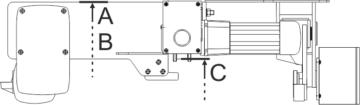
Reference edge for dimensions A, B and C on wire rope hoist U.
|
|
Reference edge for dimensions A, B and C on wire rope hoist D.
|
|
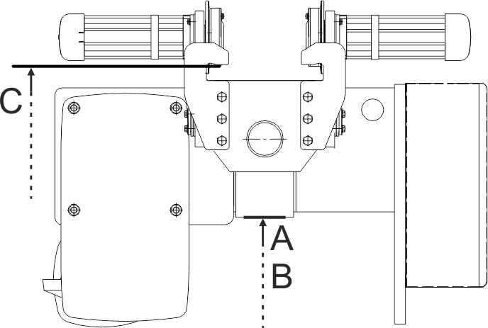
Reference edge for dimensions A, B and C on wire rope hoist DA.
|
|
Reference edge for dimensions A, B and C on wire rope hoist DQA.
|
|
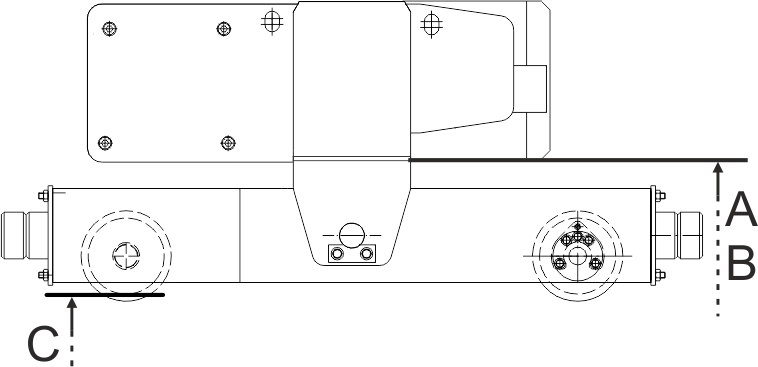
Reference edge for A-, B- and C-dimension on the wire rope hoist Z. (The reference edge for the A-, B- and C-dimension for the wire rope hoist ZA does not essentially differ).
Reference edges on the bottom block:
|
Hook headroom |
Backup limiter switching point |
|
| |
|
Bottom hoist limiter switching point |
Top hoist limiter switching point |
Fundamentally:
─ 146 rotations of the adjusting screw completely rotate the control cam on the gear limit switch 360° once.
─ How many millimetres of hook path correspond to one rotation of the adjusting screw is specified in the following table.
─ Rotating the adjusting screw to the right moves the switching point downwards, rotating the adjusting screw to the left moves the switching point upwards.
─ How many millimetres of hook path the load hook travels in the dead range of the Microswitch (switching hysteresis) is specified in the following table.
|
|
|
|
|
|
Switching
point |
Switching
point |
Dead range (switching hysteresis) |
Hook path per rotation of the adjusting screw | ||||
|
Type |
Size |
Reeving |
Track gauge [mm] |
Hook
headroom |
A1 [mm] |
B1 [mm] |
C1 [mm] |
A2 [mm] |
B2 [mm] |
C2 [mm] | ||
|
E |
800 |
4/1 |
Up to 300 |
400 |
165 |
70 |
380 |
215 |
120 |
430 |
55 |
71 |
|
E |
1000 * |
2/1 |
Up to 300 |
567 |
210 |
105 |
525 |
310 |
205 |
625 |
120 |
154 |
|
E |
1000 * |
4/1 |
Up to 300 |
500 |
230 |
125 |
480 |
279 |
175 |
530 |
60 |
77 |
|
E |
2000 |
2/1 |
Up to 300 |
580 |
180 |
70 |
540 |
280 |
170 |
640 |
130 |
172 |
|
E |
2000 |
4/1 |
Up to 300 |
500 |
195 |
80 |
480 |
245 |
130 |
530 |
65 |
86 |
|
E |
3000 |
2/1 |
Up to 300 |
664 |
215 |
70 |
625 |
315 |
170 |
734 |
160 |
214 |
|
E |
3000 |
4/1 |
Up to 300 |
580 |
235 |
90 |
560 |
285 |
140 |
610 |
80 |
107 |
|
E |
5000 |
2/1 |
Up to 350 |
830 |
295 |
110 |
790 |
395 |
210 |
890 |
178 |
238 |
|
E |
5000 |
4/1 |
Up to 350 |
825 |
375 |
190 |
805 |
425 |
240 |
855 |
89 |
119 |
|
E |
6000 |
2/1 |
Up to 350 |
830 |
295 |
110 |
790 |
395 |
210 |
890 |
194 |
260 |
Table: Hook headroom for wire rope hoists of type E. With larger track gauges please heed the following!
* The specified values apply for the GM 1000 compact and for the GM 1000 modular. The values are identical for both designs.
This section only applies to wire rope hoists of the design "E" with a larger track gauge than given in the table above.
The hook headroom has to be enlarged as of a certain track gauge.
 Add the additional dimension
from the above table to the hook headroom.
Add the additional dimension
from the above table to the hook headroom.
|
Track gauge |
Installation size
800 |
Installation size 1000
|
Installation size 1000
|
Installation size 2000
|
Installation size 2000
|
Installation size 3000
|
Installation size 3000
|
Installation size 5000
|
Installation size 5000
|
Installation size 6000
|
|
300 |
0 |
0 |
0 |
0 |
0 |
0 |
0 |
- |
- |
- |
|
350 |
49 |
39 |
45 |
43 |
53 |
62 |
80 |
0 |
0 |
0 |
|
400 |
98 |
78 |
89 |
86 |
106 |
124 |
160 |
76 |
74 |
76 |
|
450 |
146 |
117 |
134 |
129 |
159 |
187 |
240 |
152 |
148 |
152 |
|
500 |
195 |
156 |
178 |
172 |
212 |
249 |
320 |
228 |
222 |
228 |
|
550 |
- |
- |
- |
- |
265 |
311 |
401 |
304 |
296 |
304 |
|
600 |
- |
- |
- |
- |
318 |
373 |
481 |
380 |
370 |
380 |
|
650 |
- |
- |
- |
- |
371 |
435 |
561 |
456 |
444 |
456 |
|
700 |
- |
- |
- |
- |
424 |
498 |
641 |
532 |
518 |
532 |
|
|
|
|
|
Switching
point |
Switching
point |
Dead range (switching hysteresis) |
Hook path per rotation of the adjusting screw | ||||
|
Type |
Size |
Reeving |
Hook
headroom |
A1 [mm] |
B1 [mm] |
C1 [mm] |
A2 [mm] |
B2 [mm] |
C2 [mm] | ||
|
S |
800 |
4/1 |
343 |
335 |
245 |
323 |
385 |
295 |
377 |
55 |
71 |
|
S |
1000 |
4/1 |
420 |
420 |
315 |
400 |
470 |
365 |
450 |
60 |
77 |
|
S |
2000 |
4/1 |
440 |
405 |
290 |
420 |
455 |
340 |
470 |
65 |
86 |
|
S |
3000 |
2/1 |
699 |
520 |
370 |
659 |
620 |
470 |
760 |
160 |
214 |
|
S |
3000 |
4/1 |
550 |
540 |
395 |
530 |
590 |
445 |
580 |
80 |
107 |
Table: Hook headroom for wire rope hoists of type S
|
|
|
|
|
Switching
point |
Switching
point |
Dead range (switching hysteresis) |
Hook path per rotation of the adjusting screw | ||||
|
Type |
Size |
Reeving |
Hook
headroom |
A1 [mm] |
B1 [mm] |
C1 [mm] |
A2 [mm] |
B2 [mm] |
C2 [mm] | ||
|
U |
5000 |
4/1 |
1132 |
270 |
80 |
1110 |
320 |
130 |
1160 |
89 |
119 |
|
U |
6000 |
2/1 |
1256 |
235 |
50 |
1215 |
335 |
150 |
1315 |
194 |
260 |
|
U |
6000 |
4/1 |
1241 |
260 |
70 |
1220 |
310 |
120 |
1270 |
97 |
130 |
|
U |
7000 |
2/1 |
1615 |
330 |
90 |
1575 |
430 |
190 |
1675 |
254 |
342 |
Table: Hook headroom for wire rope hoists of type U
|
|
|
|
|
|
Switching
point |
Switching
point |
Dead range (switching hysteresis) |
Hook path per rotation of the adjusting screw | ||||
|
Type |
Size |
Reeving |
Track gauge [mm] |
Hook
headroom |
A1 [mm] |
B1 [mm] |
C1 [mm] |
A2 [mm] |
B2 [mm] |
C2 [mm] | ||
|
D |
800 |
4/1 |
|
144 |
170 |
80 |
125 |
220 |
130 |
175 |
55 |
71 |
|
D |
1000 |
4/1 |
|
195 |
190 |
85 |
175 |
240 |
135 |
225 |
60 |
77 |
|
D |
2000 |
2/1 |
|
295 |
160 |
50 |
255 |
260 |
150 |
355 |
130 |
172 |
|
D |
2000 |
4/1 |
|
215 |
175 |
60 |
195 |
225 |
110 |
245 |
65 |
86 |
|
D |
3000 |
2/1 |
|
315 |
190 |
45 |
275 |
290 |
150 |
375 |
160 |
214 |
|
D130 |
3000 |
4/1 |
|
260 |
230 |
85 |
240 |
280 |
134 |
290 |
80 |
107 |
|
D160 |
3000 |
4/1 |
|
260 |
225 |
80 |
240 |
275 |
129 |
290 |
80 |
107 |
|
D |
5000 |
2/1 |
|
440 |
240 |
50 |
400 |
340 |
150 |
500 |
178 |
238 |
|
D |
5000 |
4/1 |
160 |
385 |
285 |
100 |
365 |
335 |
150 |
415 |
89 |
119 |
|
D |
5000 |
4/1 |
200 |
385 |
305 |
120 |
|
355 |
170 |
|
|
|
|
D |
5000 |
4/2 |
|
320 |
330 |
220 |
280 |
430 |
320 |
380 |
178 |
238 |
|
D |
6000 |
2/1 |
|
520 |
235 |
50 |
480 |
335 |
150 |
580 |
194 |
260 |
|
D |
6000 |
4/1 |
|
267 |
260 |
73 |
247 |
310 |
123 |
297 |
97 |
130 |
|
D |
6000 |
6/1 |
|
606 |
355 |
168 |
586 |
405 |
218 |
636 |
65 |
87 |
|
D |
7000 |
2/1 |
|
572 |
344 |
103 |
532 |
444 |
203 |
632 |
254 |
342 |
|
D |
7000 |
4/1 |
|
501 |
380 |
139 |
481 |
430 |
189 |
531 |
127 |
171 |
|
D |
7000 |
6/1 |
to 2000 |
717 |
520 |
280 |
690 |
570 |
330 |
745 |
85 |
114 |
|
D |
7000 |
6/1 |
from 2000 |
897 |
520 |
280 |
875 |
570 |
330 |
925 |
85 |
114 |
|
D |
7000 |
4/2 |
|
236 |
240 |
50 |
195 |
340 |
150 |
295 |
254 |
342 |
|
D |
7000 |
8/2 |
|
516 |
260 |
70 |
495 |
310 |
120 |
545 |
127 |
171 |
Table: Hook headroom for wire rope hoists of type D
|
|
|
|
|
Switching
point |
Switching
point |
Dead range (switching hysteresis) |
Hook path per rotation of the adjusting screw | ||||
|
Type |
Size |
Reeving |
Hook
headroom |
A1 [mm] |
B1 [mm] |
C1 [mm] |
A2 [mm] |
B2 [mm] |
C2 [mm] | ||
|
DA |
800 |
4/1 |
429 |
170 |
80 |
410 |
220 |
130 |
460 |
55 |
71 |
|
DA |
1000 |
4/1 |
520 |
190 |
85 |
500 |
240 |
135 |
550 |
60 |
77 |
|
DA |
2000 |
2/1 |
621 |
160 |
50 |
580 |
260 |
150 |
681 |
130 |
172 |
|
DA |
2000 |
4/1 |
544 |
175 |
60 |
520 |
225 |
110 |
570 |
65 |
86 |
|
DA |
3000 |
2/1 |
700 |
193 |
45 |
660 |
290 |
145 |
760 |
160 |
214 |
|
DA |
3000 |
4/1 |
620 |
225 |
80 |
600 |
275 |
130 |
650 |
80 |
107 |
|
DA |
5000 |
2/1 |
825 |
240 |
50 |
785 |
340 |
150 |
885 |
178 |
238 |
|
DA |
5000 |
4/1 |
813 |
285 |
100 |
795 |
335 |
150 |
845 |
89 |
119 |
|
DA160 |
6000 |
2/1 |
949 |
235 |
50 |
910 |
335 |
150 |
1010 |
194 |
260 |
|
DA200 |
6000 |
4/1 |
470 |
260 |
70 |
450 |
310 |
120 |
500 |
97 |
130 |
|
DA280 |
6000 |
4/1 |
832 |
260 |
70 |
810 |
310 |
120 |
860 |
97 |
130 |
|
DA280 |
6000 |
6/1 |
1068 |
352 |
165 |
1050 |
400 |
215 |
1100 |
65 |
87 |
|
DA200 |
7000 |
2/1 |
1284 |
345 |
105 |
1245 |
445 |
205 |
1345 |
254 |
342 |
|
DA |
7000 |
4/1 |
913 |
375 |
135 |
895 |
425 |
185 |
943 |
127 |
171 |
|
DA |
7000 |
6/1 |
1370 |
515 |
275 |
1350 |
565 |
325 |
1400 |
85 |
114 |
Table: Hook headroom for wire rope hoists of type DA
|
|
|
|
|
Switching
point |
Switching
point |
Dead range (switching hysteresis) |
Hook path per rotation of the adjusting screw | ||||
|
Type |
Size |
Reeving |
Hook
headroom |
A1 [mm] |
B1 [mm] |
C1 [mm] |
A2 [mm] |
B2 [mm] |
C2 [mm] | ||
|
DQA |
2000 |
2/1 |
525 |
125 |
10 |
485 |
225 |
110 |
585 |
130 |
172 |
|
DQA |
2000 |
4/1 |
445 |
140 |
30 |
425 |
190 |
80 |
475 |
65 |
86 |
|
DQA |
3000 |
2/1 |
639 |
190 |
40 |
600 |
290 |
140 |
700 |
160 |
214 |
|
DQA |
3000 |
4/1 |
555 |
210 |
65 |
535 |
260 |
115 |
585 |
80 |
107 |
|
DQA |
5000 |
2/1 |
810 |
275 |
90 |
770 |
375 |
190 |
870 |
178 |
238 |
|
DQA |
5000 |
4/1 |
712 |
265 |
75 |
690 |
315 |
125 |
740 |
89 |
119 |
|
DQA |
6000 |
2/1 |
870 |
335 |
150 |
830 |
435 |
250 |
930 |
194 |
260 |
|
DQA |
6000 |
4/1 |
745 |
250 |
60 |
725 |
300 |
110 |
775 |
97 |
130 |
|
DQA350 |
7000 |
4/1 |
970 |
375 |
135 |
950 |
425 |
185 |
1000 |
127 |
171 |
Table: Hook headroom for wire rope hoists of type DQA
|
|
|
|
|
|
Switching
point |
Switching
point |
Dead range (switching hysteresis) |
Hook path per rotation of the adjusting screw | ||||
|
Type |
Size |
Reeving |
Track gauge [mm] |
Hook
headroom |
A1 [mm] |
B1 [mm] |
C1 [mm] |
A2 [mm] |
B2 [mm] |
C2 [mm] | ||
|
Z |
5000 |
4/2 |
|
413 |
490 |
300 |
375 |
590 |
400 |
475 |
178 |
238 |
|
Z |
5000 |
8/2 |
|
631 |
505 |
315 |
610 |
555 |
365 |
660 |
89 |
119 |
|
Z |
6000 |
4/2 |
|
414 |
485 |
300 |
375 |
585 |
400 |
475 |
194 |
260 |
|
Z280 |
6000 |
8/2 |
|
638 |
450 |
310 |
620 |
550 |
360 |
670 |
97 |
130 |
|
Z350 |
6000 |
8/2 |
|
643 |
450 |
260 |
625 |
500 |
310 |
675 |
97 |
130 |
|
Z |
7000 |
4/2 |
|
668 |
525 |
285 |
630 |
625 |
385 |
730 |
254 |
342 |
|
Z |
7000 |
6/2 |
to 2000 |
717 |
522 |
281 |
697 |
572 |
331 |
747 |
170 |
228 |
|
Z |
7000 |
6/2 |
from 2000 |
897 |
522 |
281 |
877 |
572 |
331 |
927 |
170 |
228 |
|
Z |
7000 |
8/2 |
|
915 |
525 |
284 |
895 |
575 |
334 |
945 |
127 |
171 |
|
Z |
7000 |
10/2 |
|
960 |
482 |
241 |
940 |
532 |
291 |
990 |
102 |
137 |
|
Z |
7000 |
12/2 |
|
1378 |
761 |
482 |
1358 |
811 |
532 |
1408 |
85 |
114 |
Table: Hook headroom for wire rope hoists of type Z
|
|
|
|
|
Switching
point |
Switching
point |
Dead range (switching hysteresis) |
Hook path per rotation of the adjusting screw | ||||
|
Type |
Size |
Reeving |
Hook
headroom |
A1 [mm] |
B1 [mm] |
C1 [mm] |
A2 [mm] |
B2 [mm] |
C2 [mm] | ||
|
ZA |
5000 |
8/2 |
1195 |
495 |
305 |
1175 |
545 |
355 |
1225 |
89 |
119 |
|
ZA280 |
6000 |
8/2 |
1253 |
495 |
305 |
1235 |
545 |
355 |
1285 |
97 |
130 |
|
ZA350 |
6000 |
8/2 |
1163 |
445 |
255 |
1145 |
495 |
305 |
1195 |
97 |
130 |
|
ZA |
7000 |
6/2 |
1370 |
515 |
275 |
1350 |
565 |
325 |
1400 |
170 |
228 |
|
ZA |
7000 |
8/2 |
1430 |
515 |
275 |
1410 |
565 |
325 |
1460 |
127 |
171 |
|
ZA |
7000 |
10/2 |
1312 |
480 |
240 |
1290 |
530 |
290 |
1340 |
102 |
137 |
Table: Hook headroom for wire rope hoists of type ZA
The backup limiter switching point may only be adjusted by a qualified person for service purposes.
|
|
Dimensions A1, B1, C1 |
|
| |
Bypass top hoist limiter
manually, so that the backup limiter can be travelled to.
Raise the load hook up to
dimension A1, B1 or C1.
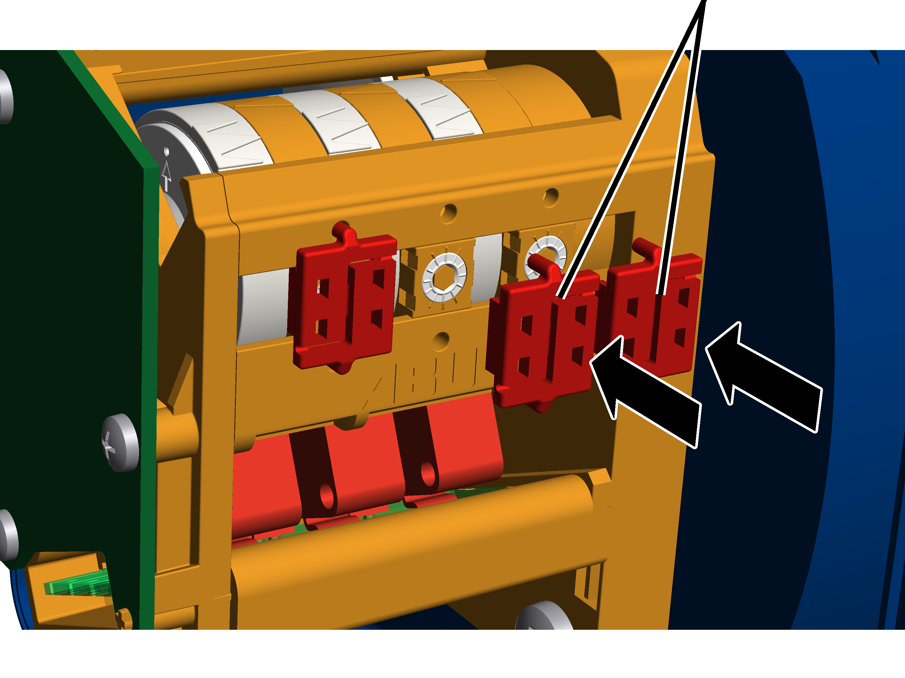
|
|
Seals |
|
| |
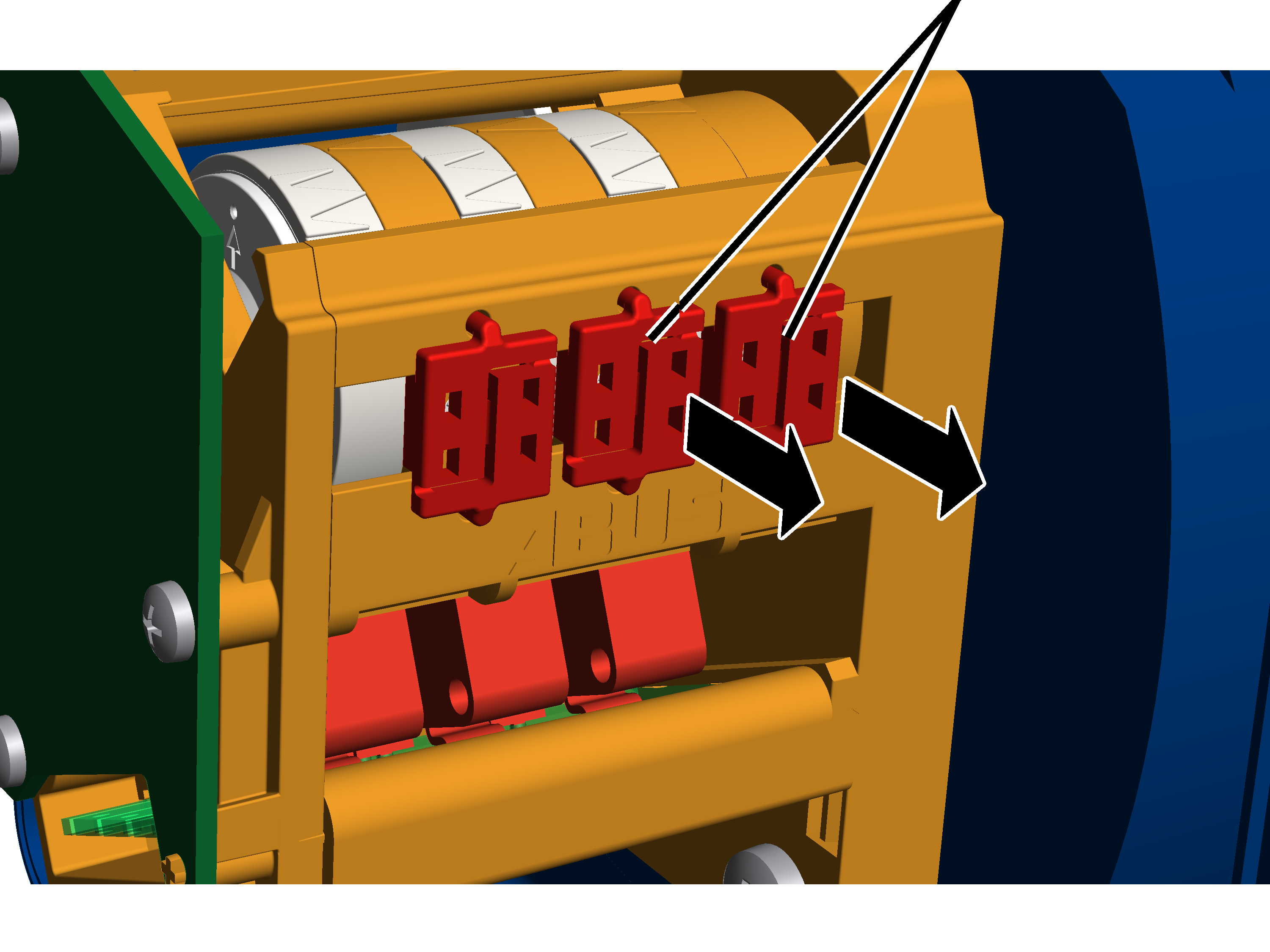
Open the housing cover of the
hoist limit switch enclosure on the cable drum.
Press the seals apart in the
centre with a screwdriver and remove them.
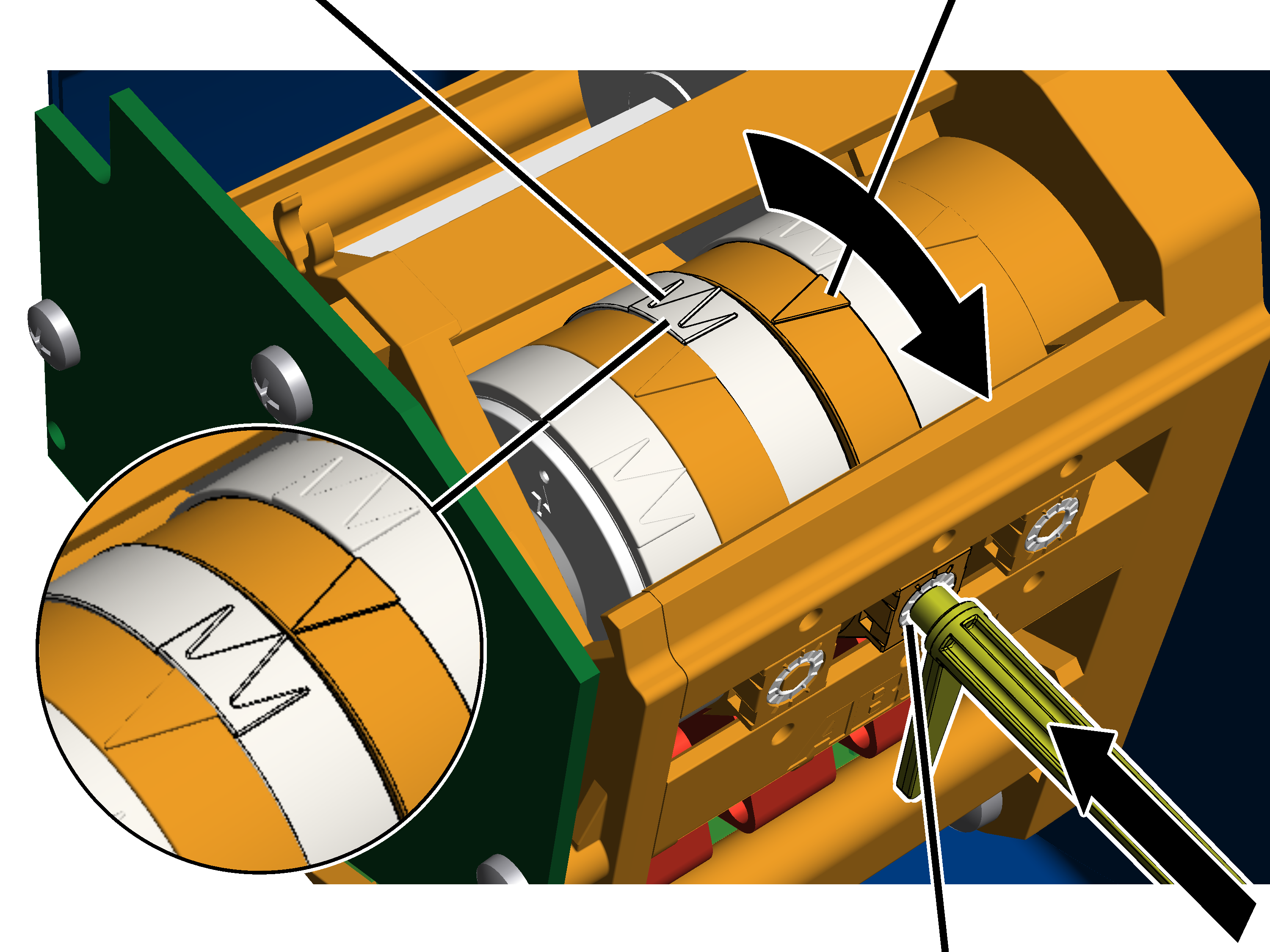
The backup limiter is set with the right adjusting screw.
|
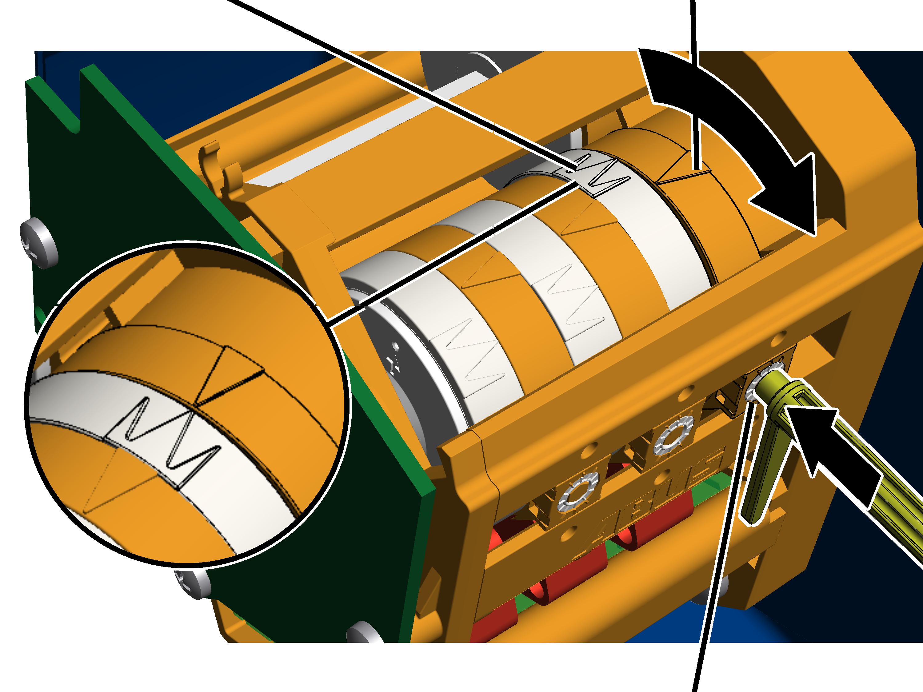
White pointer of cam ring |
Orange pointer |
|
| |
|
|
Right adjusting screw |
Remove the adjusting key. It is
fastened on two mounts on the gear limit switch.
Alternatively, a hexagon wrench key size 3.0 (ideally with rotary plate) can be used.
An electrically operated screwdriver may NOT be used.
Press the adjusting key into the
adjusting screw. Press it into the adjusting screw with light pressure.
If necessary: Turn the adjusting
screw until the white pointer of the cam ring lies to the left of the orange
pointer. It should be neither to the right of the orange pointer nor exactly on
it.
The middle white arrow shows the exact position of the switching point; the two white arrows to the left and right of it indicate the start and end of the switching phase (switching hysteresis).
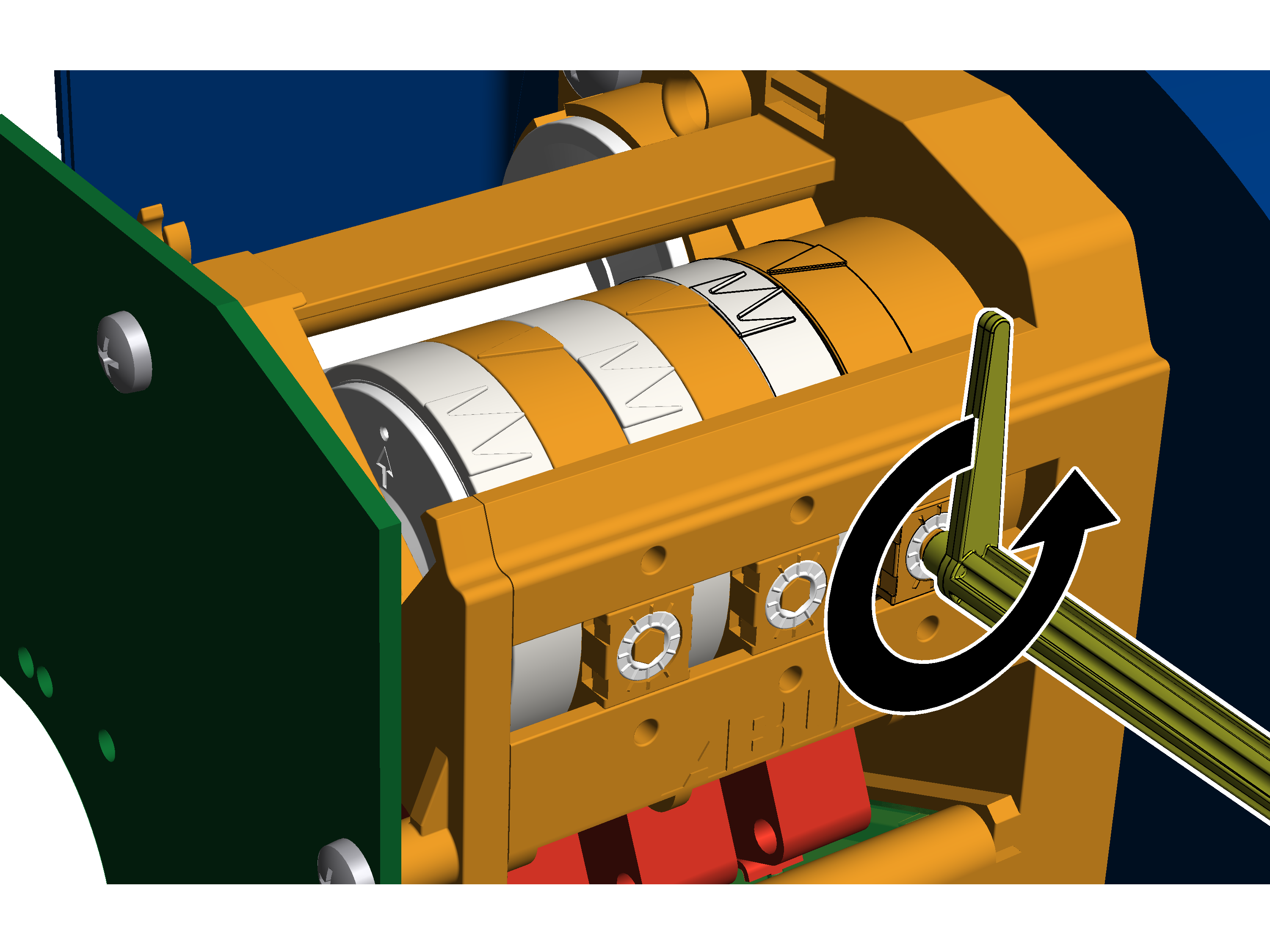
If necessary: Turn the adjusting
screw until the white pointer of the cam ring rotates clockwise. Continue
turning until the white pointer lies exactly on the orange pointer and a
clicking sound is audible.
─ Turning to the right shifts the switching point downward.
─ Turning to the left shifts the switching point upward.
The main contactor switches
off.
|
|
Turn the adjusting screw
three-quarters of a turn to the left.
● The microswitch switches again; the main contactor switches back on.
Lower the load hook
slightly.
Turn the adjusting screw
three-quarters of a turn back to the right.
|
| |
|
|
Dimensions A2, B2, C2 |
Move the load hook up to
dimension A2, B2 or C2.
The top hoist limiter is set with the middle adjusting screw.
|
White pointer of cam ring |
Orange pointer |
|
| |
|
|
Middle adjusting screw |
Remove the adjusting key. It is
fastened on two mounts on the gear limit switch.
Alternatively, a hexagon wrench key size 3.0 (ideally with rotary plate) can be used.
An electrically operated screwdriver may NOT be used.
Press the adjusting key into the
adjusting screw. Press it into the adjusting screw with light pressure.
If necessary: Turn the adjusting
screw until the white pointer of the cam ring lies to the left of the orange
pointer. It should be neither to the right of the orange pointer nor exactly on
it.
The middle white arrow shows the exact position of the switching point; the two white arrows to the left and right of it indicate the start and end of the switching phase (switching hysteresis).
If necessary: Turn the adjusting
screw until the white pointer of the cam ring rotates clockwise. Continue
turning until the white pointer lies exactly on the orange pointer and a
clicking sound is audible.
─ Turning to the right shifts the switching point downward.
─ Turning to the left shifts the switching point upward.
Lower the load hook.
● Lift the load hook at both slow and fast lifting speed and check whether it halts at the correct point.
|
|
Seals |
|
| |
Insert seals (2x) onto the
adjusting screws and press them in.