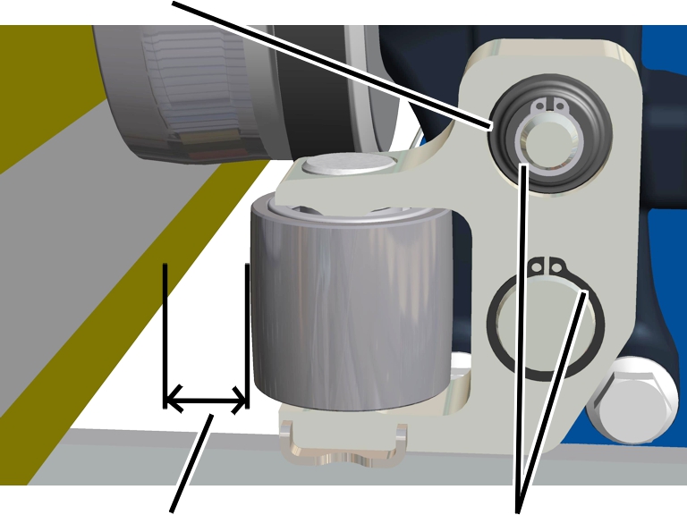
Wheel
Guide roller
Main girder lower flange
Diameter
The pictures show the procedure on a GM 1000 modular wire rope hoist. The procedure on GM 800 does not differ significantly from this.
On all four guide rollers:
|
Wheel |
Guide roller |
|
| |
|
Main girder lower flange |
Diameter |
 Measure the diameter of the guide roller.
The diameter may not be smaller than is specified in the table.
|
Guide roller |
Minimum diameter |
Diameter of a new guide roller |
|
GM800 |
41 mm |
44 mm |
|
GM1000 |
41 mm |
44 mm |
 If the diameter is less than the diameter specified in the table:
Replace the guide roller. See Replacing the guide
roller and rubber spring element.
If the diameter is less than the diameter specified in the table:
Replace the guide roller. See Replacing the guide
roller and rubber spring element.
On all four guide rollers:
|
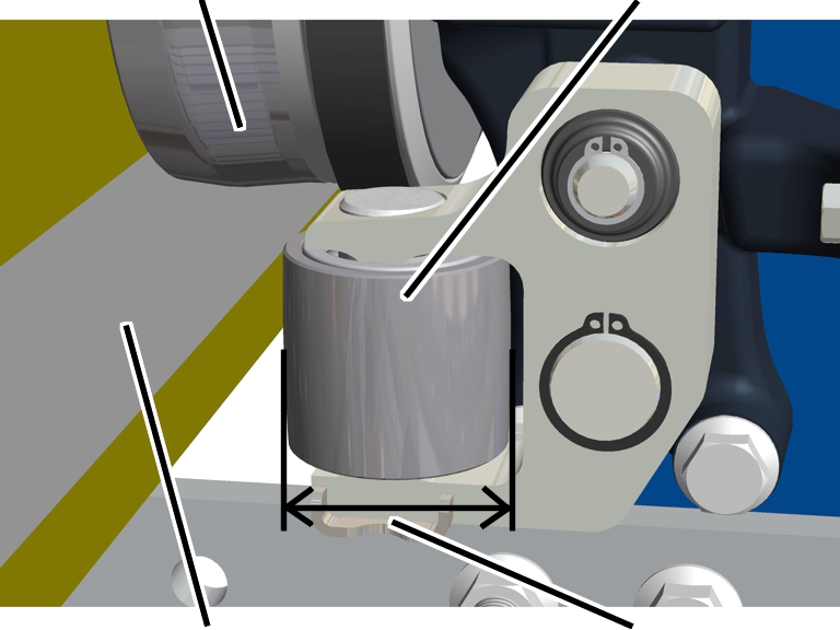
Rubber spring element |
|
|
| |
|
Spacing between the guide roller and lower flange |
Circlip |
On the counterweight side: Measure the spacing at the front and rear
between the lower flange and the guide roller.
The maximum spacing between the guide roller and lower flange must
not exceed 2 mm.
If the spacing is larger: Adjust the guide roller. See Adjusting the guide
rollers.
On all four guide rollers:
Turn the guide roller. It must turn easily.
Inspect the guide roller. It may not exhibit any signs of damage and
the surface may not exhibit any undercuts.
If the guide roller is damaged: Replace the guide roller. See Replacing the guide
roller and rubber spring element.
Inspect the rubber spring element. It may not exhibit any damage.
If the rubber spring element is damaged: Replace the rubber spring
element. See Replacing the guide
roller and rubber spring element.
Inspect the circlips (2x). They must be installed and firmly locked
in place.
If a circlip is missing: Replace the circlip.