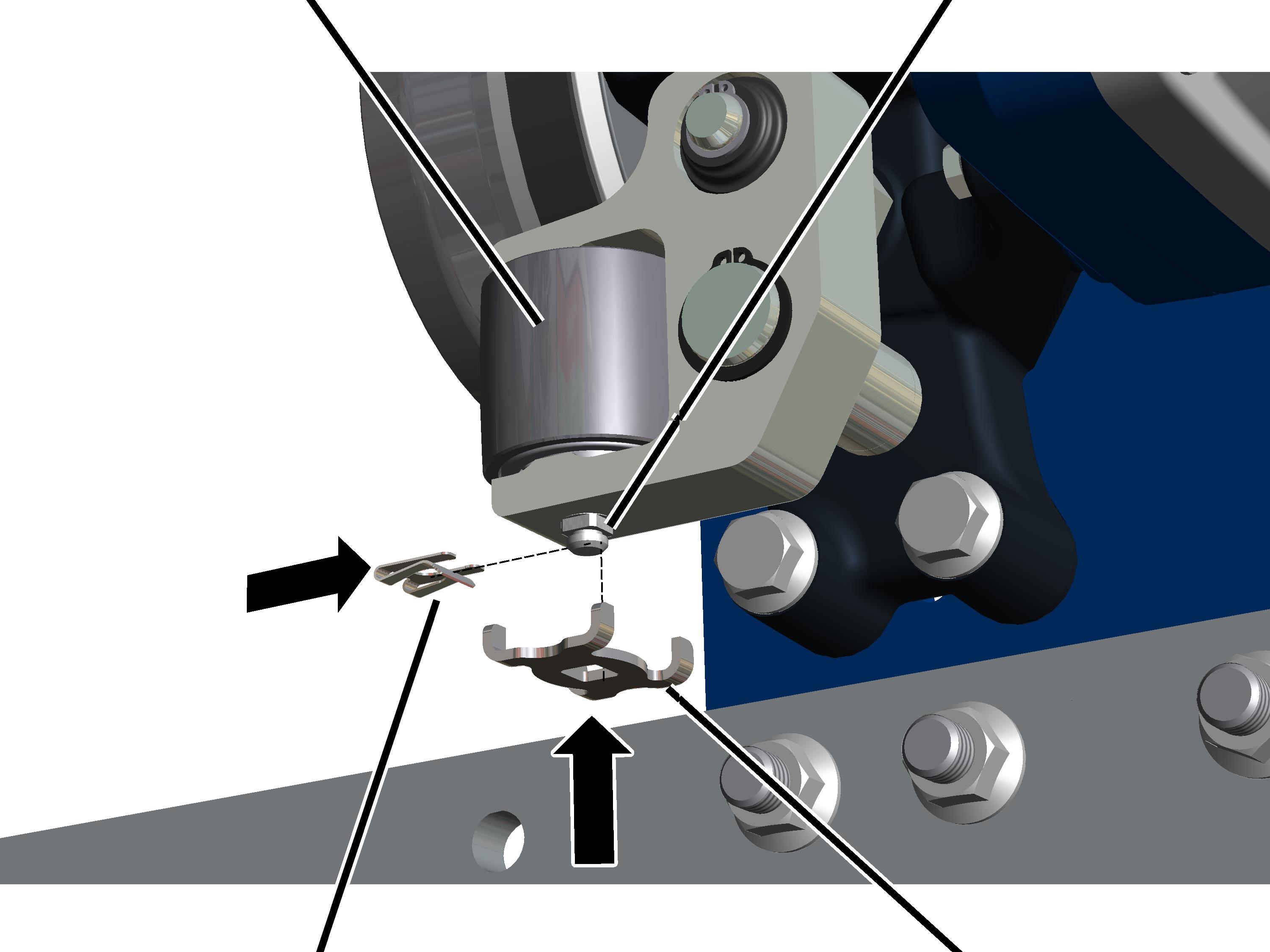
Bearing bolt

SL safety clip
Safety plate
If the spacing between the guide rollers and the lower flange is larger than permitted, then the guide rollers must be adjusted.
A bearing bolt can be used to adjust the guide rollers in three steps to -2 mm, ±0 mm and +2 mm.
The pictures show the procedure on a GM 1000 modular wire rope hoist. The procedure on GM 800 does not differ significantly from this.
In order to correctly adjust the guide rollers, they must first all be set to a neutral position.
On all four guide rollers:
|
Bearing bolt | |
|
| |
|
SL safety clip |
Safety plate |
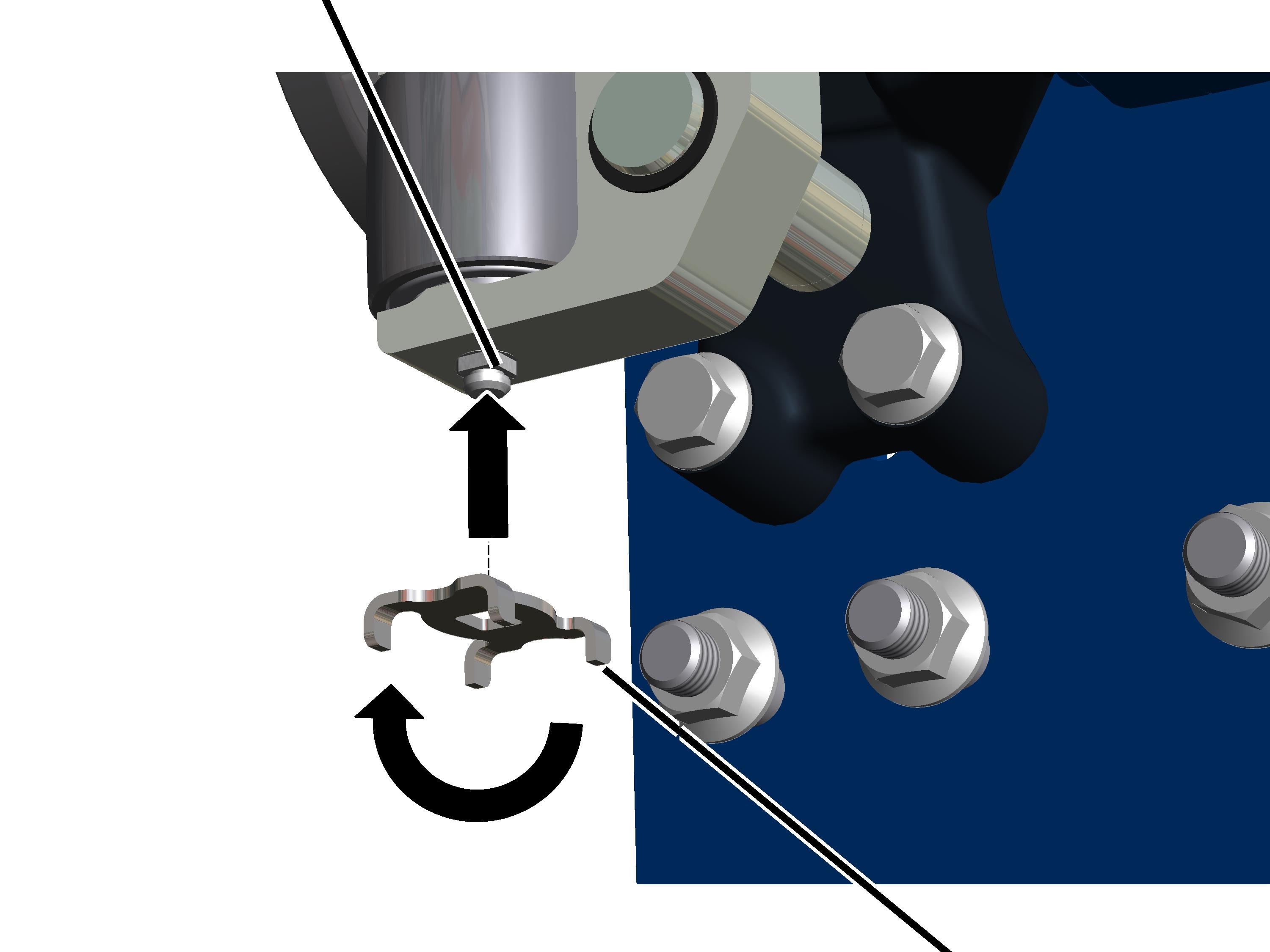
 Remove the SL safety clip.
Remove the safety plate from the
bearing bolt by pulling it downwards.
The safety plate is used as an adjusting aid for the guide roller in the next step.
|
Bearing bolt |
|
|
| |
|
|
Safety plate |
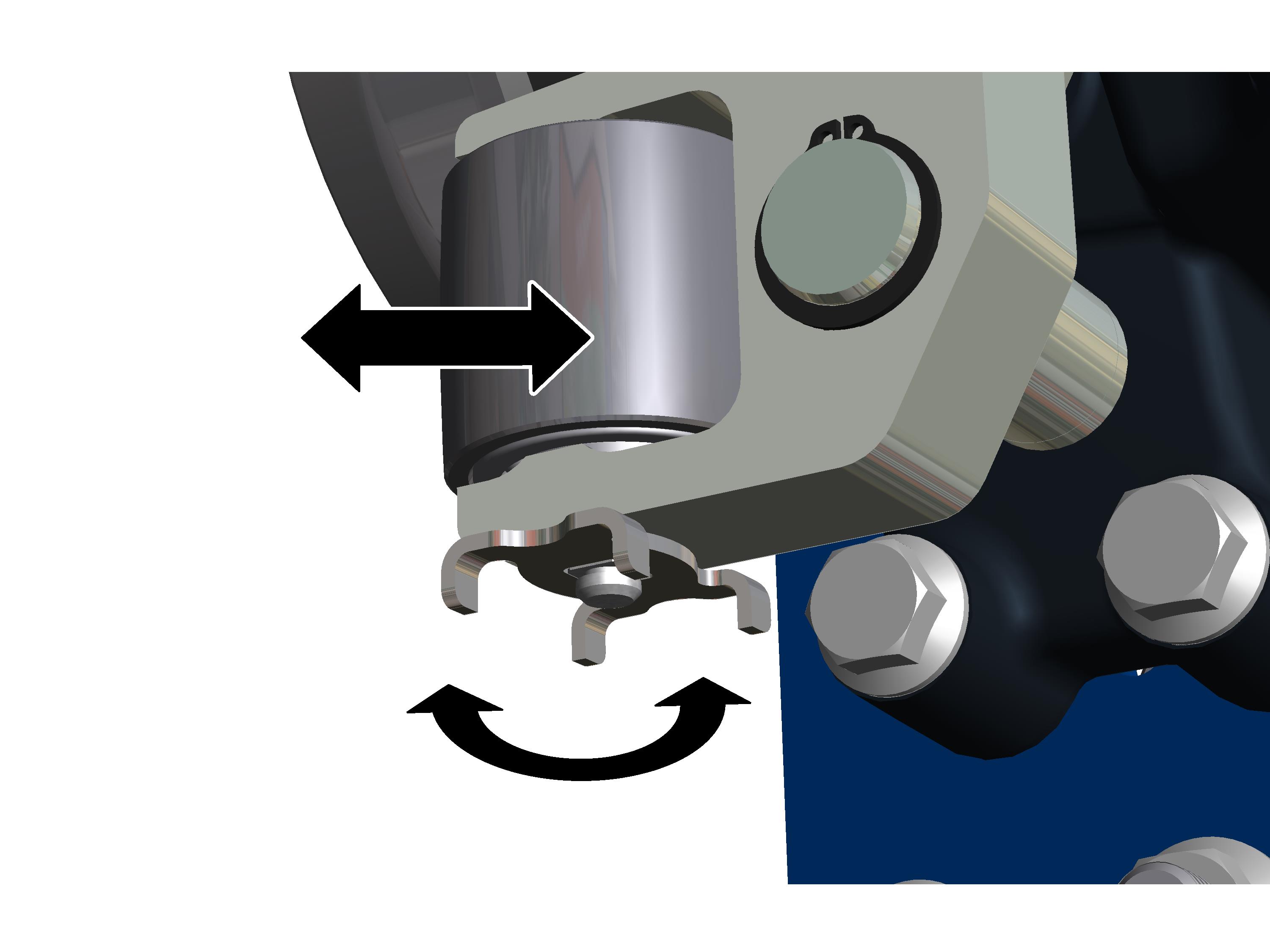
 Turn the safety plate so the
load hooks face downwards.
Turn the safety plate so the
load hooks face downwards.
Fit the safety plate onto the
bearing bolt.
|
|
Turn the guide roller using the
safety plate in increments of 90 degrees so that the guide roller is positioned
in the middle (neutral position). It should not face inwards towards the main
girder and should not face outwards towards the wire rope hoist.
Push the wire rope hoist on the
drum side with the guide rollers completely onto the lower flange of the main
girder.
On the counterweight side:
|
| |
|
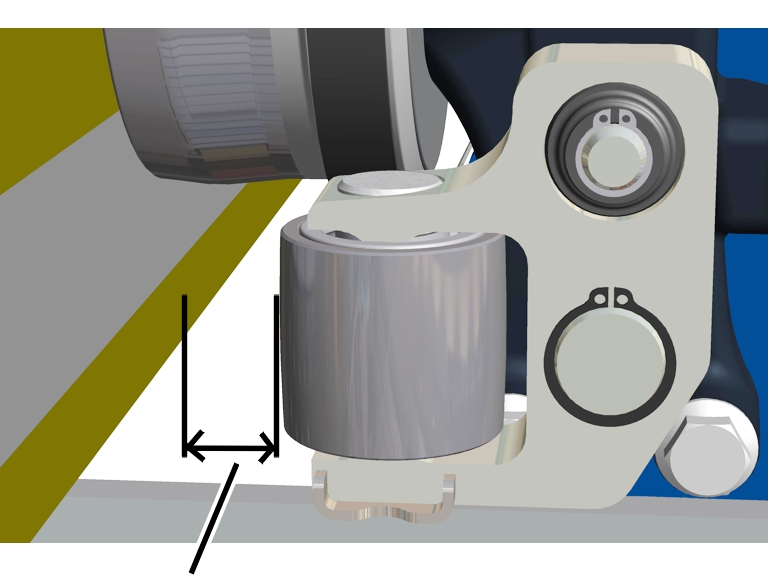
Spacing between the guide roller and lower flange |
|
Measure the spacing between the
guide rollers and the lower flange on the counterweight side.
The spacing between the guide rollers and the lower flange of the main girder is usually adjusted using the guide rollers on the counterweight side. Only when adjustment on the counterweight is not possible should the guide rollers on the drum side also be adjusted.
On all four guide rollers:
|
|
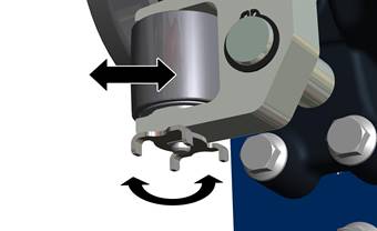
Adjust the guide roller in
increments of 90 degrees as specified in the following table.
The guide rollers can be adjusted in three steps to -2 mm, ± 0 mm and +2 mm.
─ Turn the guide roller away from the lower flange for positive values (increase spacing).
─ Turn the guide roller towards the lower flange for negative values (decrease spacing).
|
Spacing between the guide roller and lower flange [mm] |
Setting on the counterweight side |
Setting on the drum side |
|
0.5 to 2.5 |
±0 mm |
±0 mm |
|
2.5 to 4.5 |
-2 mm |
±0 mm |
|
4.5 to 6.5 |
-2 mm |
-2 mm |
On all four guide rollers:
|
Guide roller |
Bearing bolt |
|
| |
|
SL safety clip |
Safety plate |
Pull the safety plate from the
bearing bolt.
Turn the safety plate so the
load hooks face upwards.
Fit the safety plate onto the
bearing bolt.
Attach the SL safety clip.