Wire rope
Fixed point crosshead
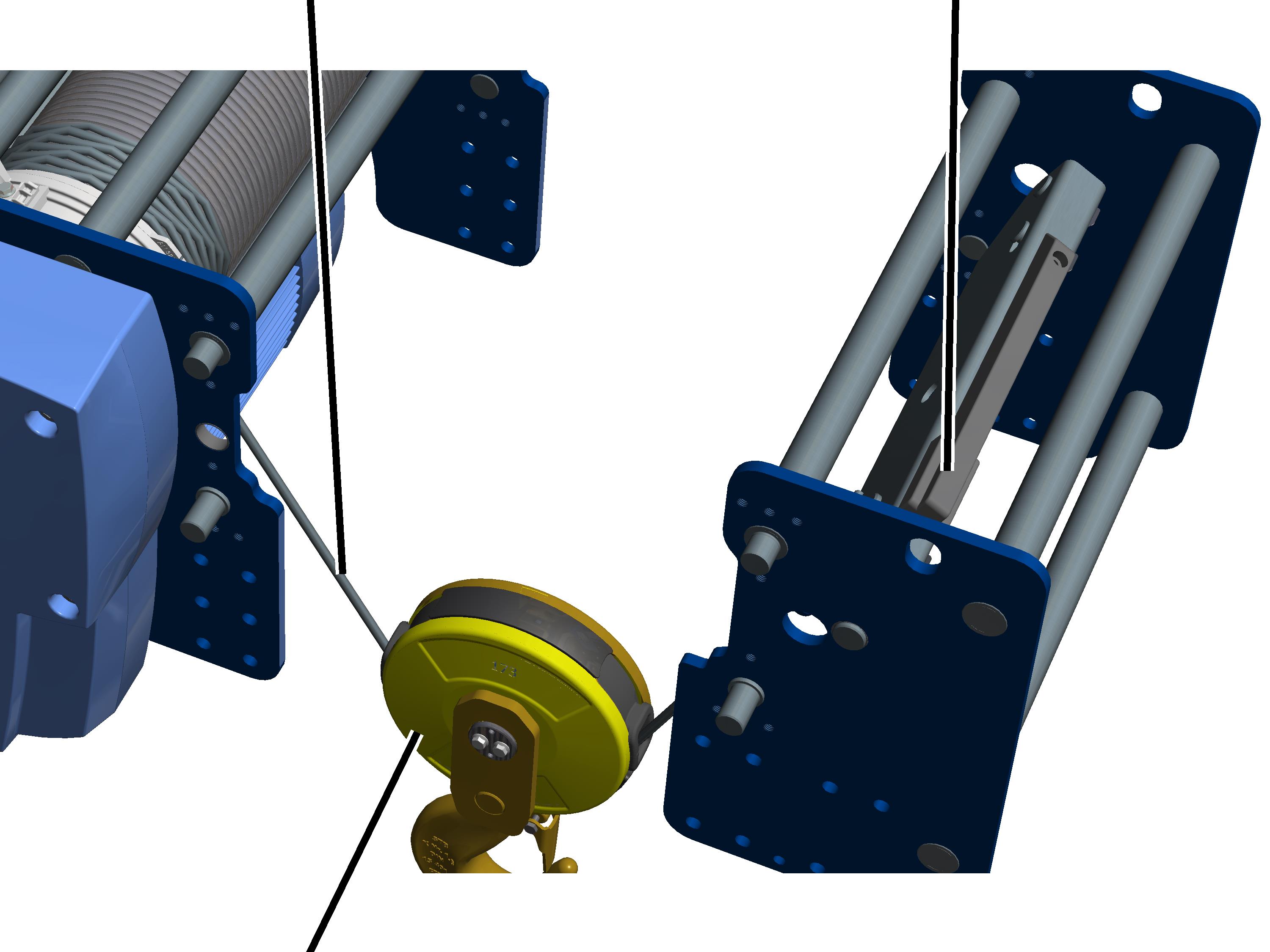
Bottom block
If necessary, the wire rope hoist reeving can be changed from twin-fall reeving (2/1) to four-fall reeving (4/1). This may be necessary if the conditions in which the wire rope hoist is used change, or if a new or a used wire rope hoist is resold.
The pictures show the procedure on a GM 1000 modular wire rope hoist. The procedure on GM 800 does not differ significantly from this.
Overview of the conversion:
This is an overview of the conversion for changing the reeving on the wire rope hoist. The individual steps are described in detail on the next pages.
|
Wire rope |
Fixed point crosshead |
|
| |
|
Bottom block |
|
Twin-fall wire rope hoist before conversion
─ To change the reeving to 4/1, the following, new components are necessary: A new wire rope, a new bottom block, deflection roller crosshead, bearing bushes (2x) for the fixed point crosshead, bearing bushes (2x) for the deflection roller crosshead.
If rope socket and rope wedge are undamaged, they may be reused. If the components are damaged however, they must be replaced.
─ Two new bearing bushes for the fixed point crosshead must be driven in on the drum side.
─ Two new bearing bushes must be driven out of the previous fixed point crosshead on the counterweight side, two new bearing bushes for the deflection roller crosshead must be driven in, the fixed point crosshead must be converted and the deflection roller crosshead must be installed.
─ A new type plate then needs to be affixed.
─ A new test log book is required for the wire rope hoist. This new test log book can be issued by ABUS. See ABUS Service.
─ Before the wire rope hoist is used for operation, a test for major changes must be carried out. See “General Product Manual for ABUS Cranes”.
─ The hoist limit switch must be readjusted.
─ The overload protection must be readjusted.
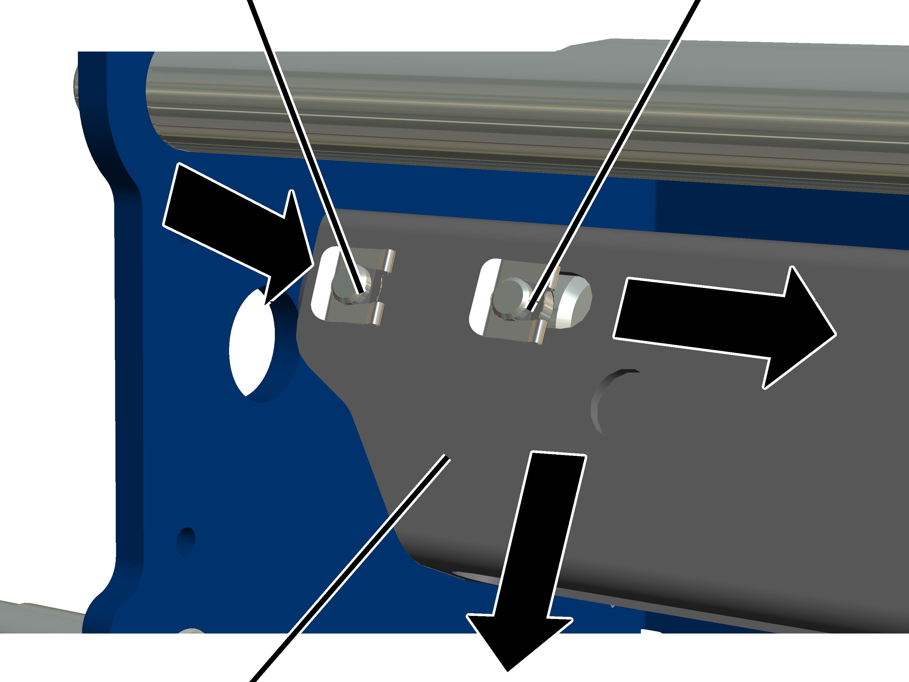
On the counterweight side:
|
Outer bolt with SL safety clip |
Inner bolt with SL safety clip |
|
| |
|
Fixed point crosshead |
|
 Remove the SL safety clip of the
outer bolt and push the bolt out.
Remove the SL safety clip of the
outer bolt and push the bolt out.
Hold the fixed point crosshead
and push the inner bolts inwards.
Pull the deflection roller
crosshead / fixed point crosshead out of side panel bearing bush on the
opposite-lying side.
● The fixed point crosshead is released.
Remove the fixed point crosshead
from the wire rope hoist from the bottom.
The bearing bushes for the previous fixed point crosshead must be driven out on the counterweight side, and two new bearing bushes for the deflection roller crosshead must be driven in next to them.
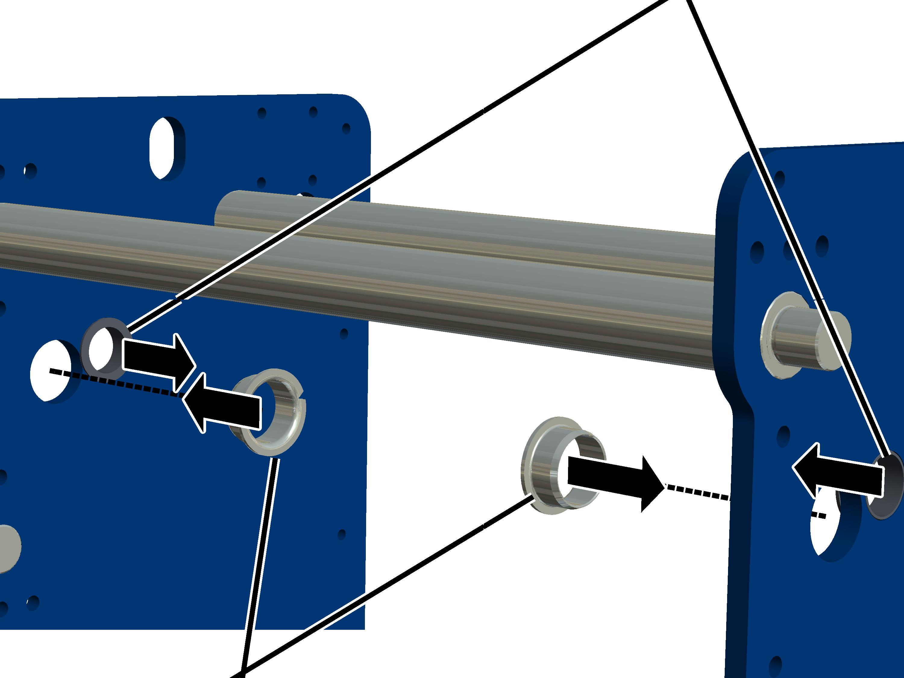
On the side panel for the deflection roller crosshead (counterweight side):
|
|
Current bearing bushes for the fixed point crosshead |
|
| |
|
New bearing bushes for the deflection roller crosshead |
|
Hold the bearing bushes for the
deflection roller crosshead at the opening (facing the outer side) from the
inside.
Drive the bearing bushes (e.g.
using a striking tool) into the side panel uniformly.
Drive out the existing bearing
bushes for the previous fixed point crosshead.
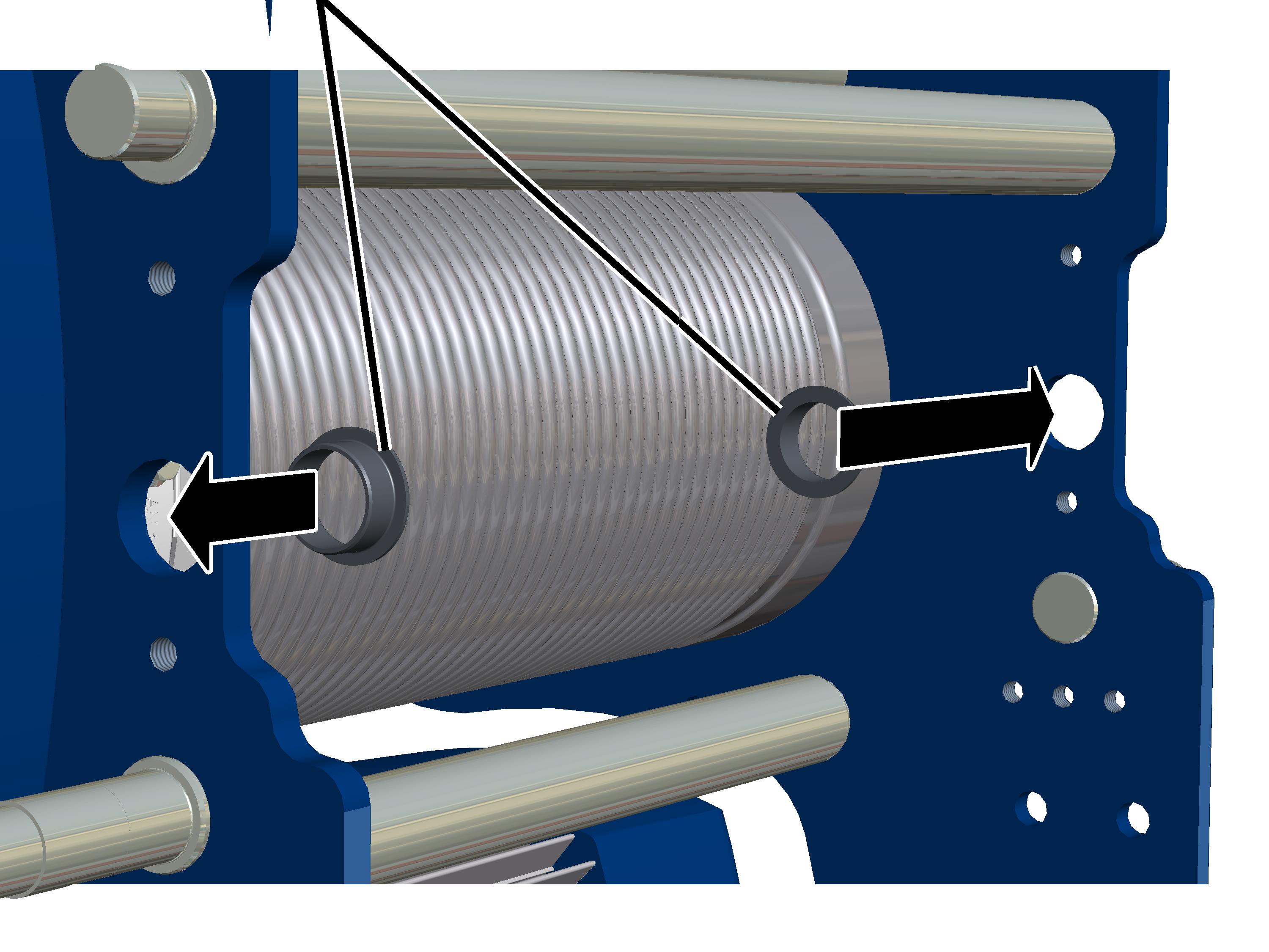
On the side panel for the fixed point crosshead (drum side):
|
New bearing bushes for the fixed point crosshead |
|
|
| |
 Hold the bearing bushes at the
opening (facing the outer side).
Hold the bearing bushes at the
opening (facing the outer side).
Drive the bearing bushes (e.g.
using a striking tool) into the side panel uniformly.
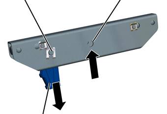
|
Drilled hole for reeving 2/1 |
Drilled hole for reeving 4/1 |
|
| |
|
Rope socket |
|
 Remove the SL safety clip and
bolts from the rope socket.
Remove the SL safety clip and
bolts from the rope socket.
 Remove the rope socket from the
fixed point crosshead.
Remove the rope socket from the
fixed point crosshead.
If rope socket and rope wedge are undamaged, they may be reused. If the components are damaged however, they must be replaced.
Push the rope socket on the
drilled hole for reeving 4/1 into the fixed point crosshead from below.
Secure the rope socket using the
bolt and SL safety clip.
Install the fixed point
crosshead on the drum side.
Observe the label on the fixed point crosshead regarding the installation direction.
Lubricant: “High-Lub LT1 EP”. For details, see Lubricants.
Install the deflection roller
crosshead on the counterweight side.
Lubricant: “High-Lub LT1 EP”. For details, see Lubricants.
Fit a new, longer wire rope.
Pull the wire rope through a
deflection roller on the bottom block for 4/1.
Pull the wire rope through the
deflection roller crosshead.
Pull the wire rope through the
other deflection roller on the bottom block for 4/1.
Fasten the wire rope onto the
fixed point crosshead.
Affix a type plate on the wire
rope hoist.
For further details on the listed assembly steps, see Replacing the wire rope, cable guide, rope socket and rope wedge.
If the wire rope hoist has
already been in use: Determine the remaining service life and inform ABUS
Service.
Request a new test log book from
ABUS Service. See ABUS
Service.
Carry out a test for major
changes. See “General Product Manual for ABUS Cranes”.
Readjust the overload
protection. See product manual “ABUS Load indicator system”.
Readjust the hoist limit switch.
See product manual “ABUS gear limit switch”.