Run the load hook to the highest
hook position.
Run the load hook to the highest
hook position.
If the wire rope is damaged or has more broken wires than permitted (see Inspecting the wire rope), it must be replaced.
If the cable guide is damaged (see Inspecting the cable guide), it must be replaced.
The wire rope and cable guides are wearing parts that are subject to heavy loads. They subject each other to wear during operation. This is why the wire rope and cable guide should always be replaced together.
The wire rope is a special lifting rope with a very high breaking strength. This ensures it has a longer service life than a normal wire rope. This is why only genuine wire ropes from ABUS may be used.
These safety instructions apply specifically to changing the wire rope:
─ Cordon off a generous space for the work area under the wire rope hoist.
─ Ensure the floor is swept clean.
This reduces soiling of the new wire rope.
─ Scissors lift platform with adequate surface area for setting down the bottom block.
Observe the load capacity of the lift platform!
─ If an unrolling device is available to unroll the wire rope, sufficient free space for this is required.
─ Position a scrap container or similar receptacle in the immediate vicinity of the lift platform and bottom block for the old wire rope.
─ For a wire rope diameter larger than 11 mm, the rope change should be performed with the aid of a second person.
Run the load hook to the highest
hook position.
Only with ABUS electrics 3 with ABULiner: move the load hook under the upper limit switch range.
Measure, and note, the position
of the load hook.
This makes adjusting the hoist limit switch after replacing the wire rope in many cases unnecessary.
If ABUControl is installed for the wire rope hoist, refer to the product manual “ABUControl”, section “Exchanging the wire rope” to prepare for the rope change.
Further steps for the wire rope change are then described in this product manual.
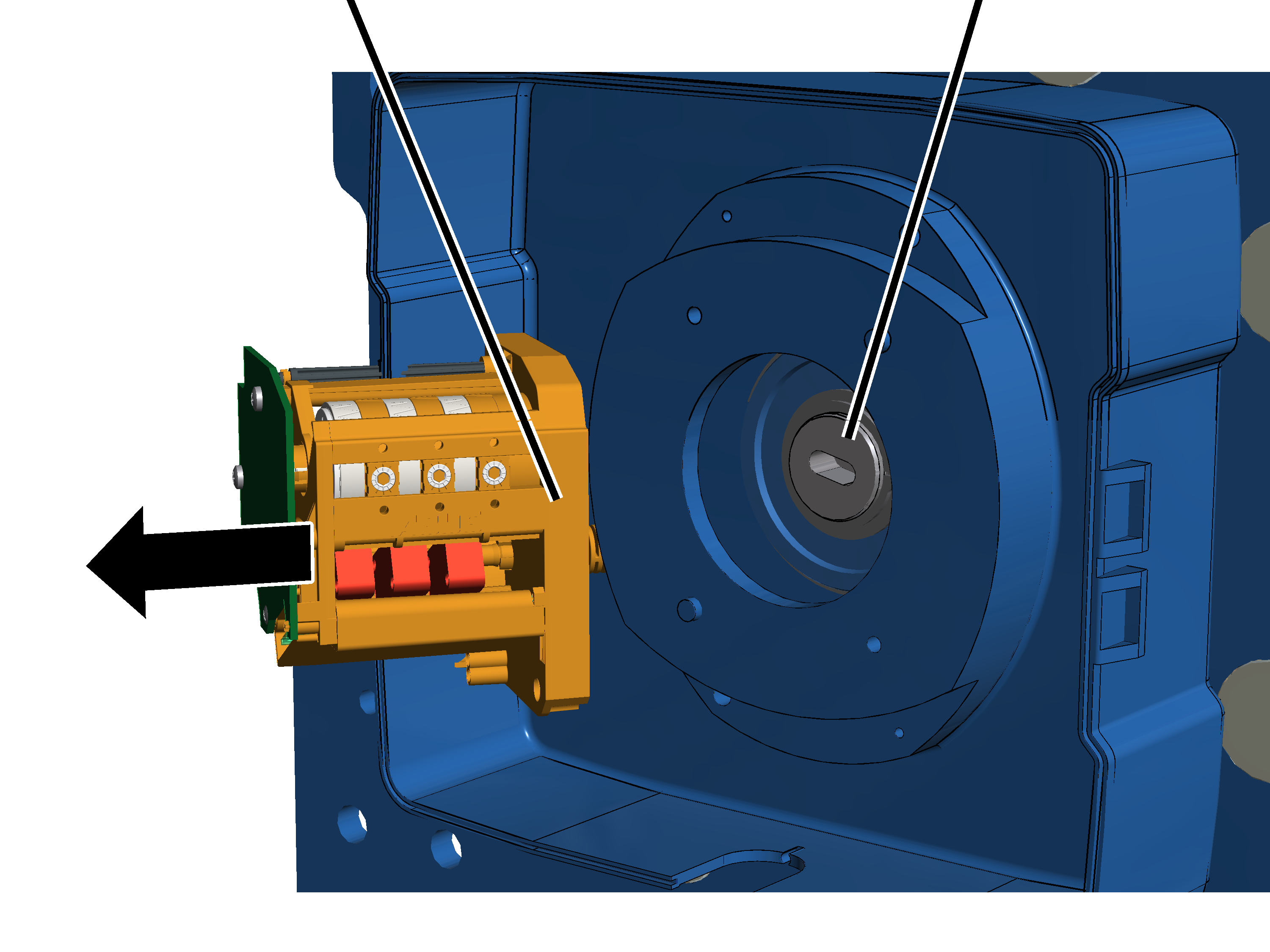
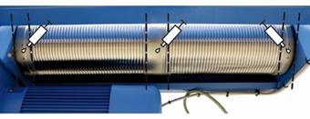
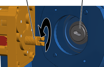
In order for the wire rope to be unwound from the cable drum using a motor, the hoist limit switch must be removed. Otherwise the cable drum will stop at the lowest hook position.
|
Hoist limit switch |
Pins on the cable drum |
|
| |
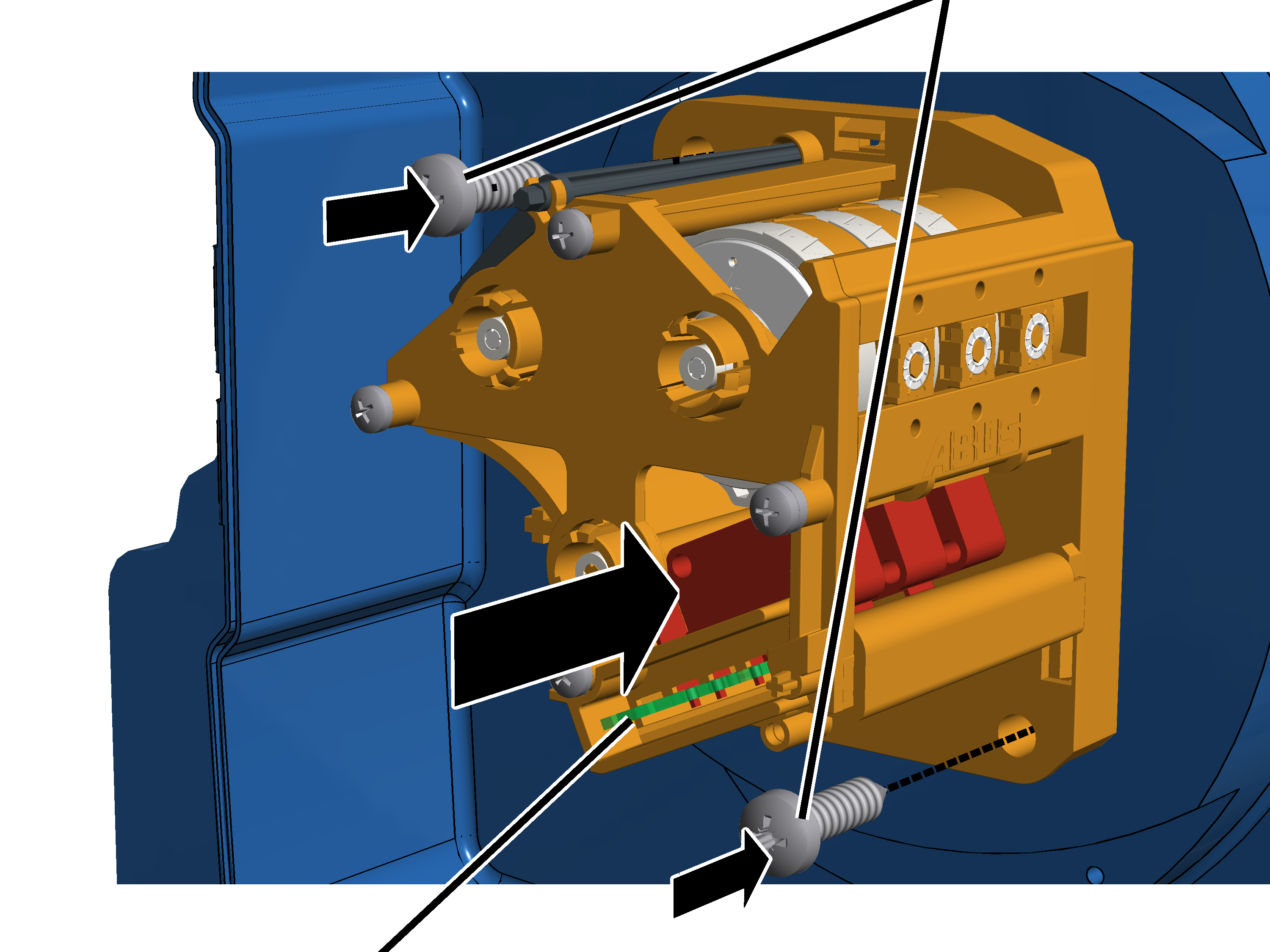
Open the hoist limit switch
housing.
Unscrew and remove screws
(2x).
Pull off the hoist limit
switch.
Leave the shaft of the hoist
limit switch in the same position, and do not turn it.
This makes adjusting the hoist limit switch after replacing the wire rope in many cases unnecessary.
Secure the hoist limit switch to
ensure it does not fall down or hang from the connection cables.
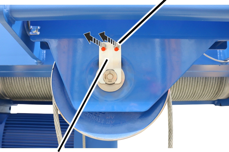
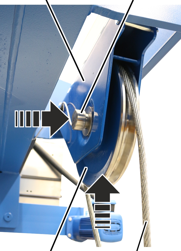
For reeving 4/2 and 8/2, both fixed points for the wire rope are on the cable drum. To replace the wire rope, the deflection roller on the trolley frame side must be removed first so the wire rope can then be wound from the cable drum.
|
|
Rib screw |
|
| |
|
Mount |
|
Release the rib screws on the
mount.
|
|
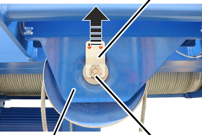
Mount |
|
| |
|
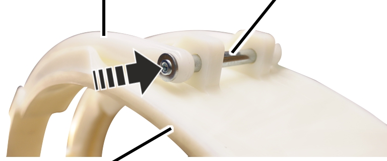
Deflection roller crosshead |
Measurement bolt |
Pull the mount of the
measurement bolt.
|
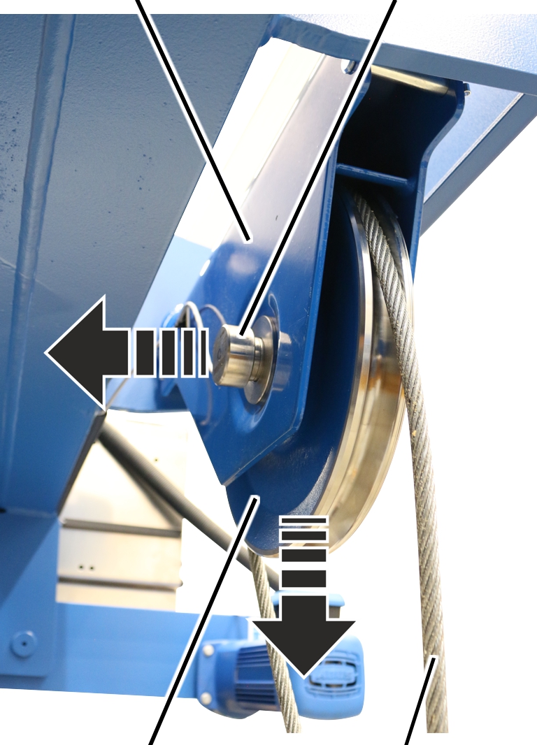
Deflection roller crosshead |
Measurement bolt |
|
| |
|
Deflection roller |
Wire rope |
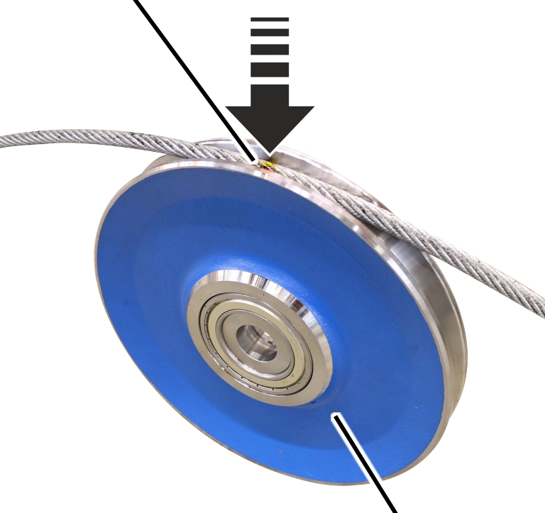
 Pull the measurement bolt out of
the deflection roller crosshead and deflection roller.
Pull the measurement bolt out of
the deflection roller crosshead and deflection roller.
Pull the deflection roller out
of the deflection roller crosshead.
|
|
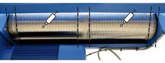
Allow the wire rope to run off the
cable drum using the motor.
Several wire rope windings should remain on the cable drum.
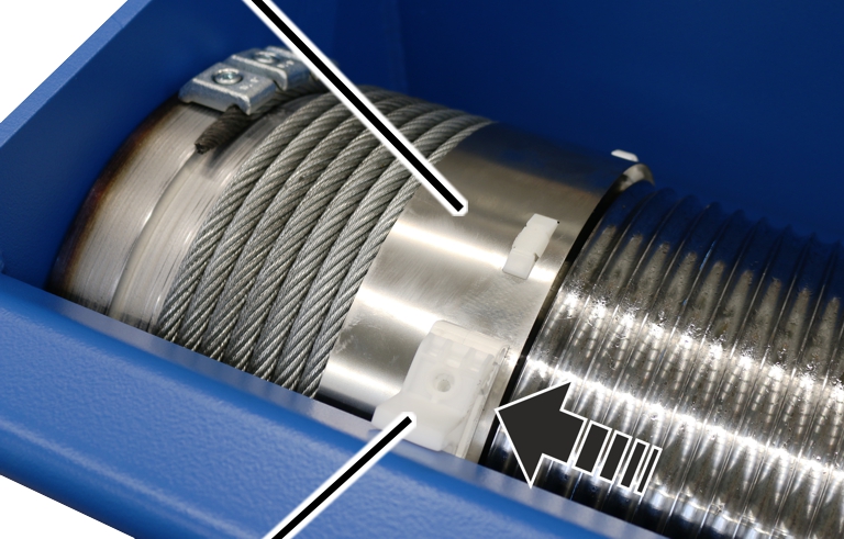
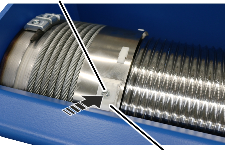
On both sides of the cable drum:
|
Self-tapping screw |
|
|
| |
|
|
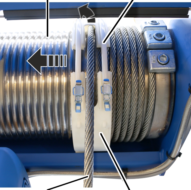
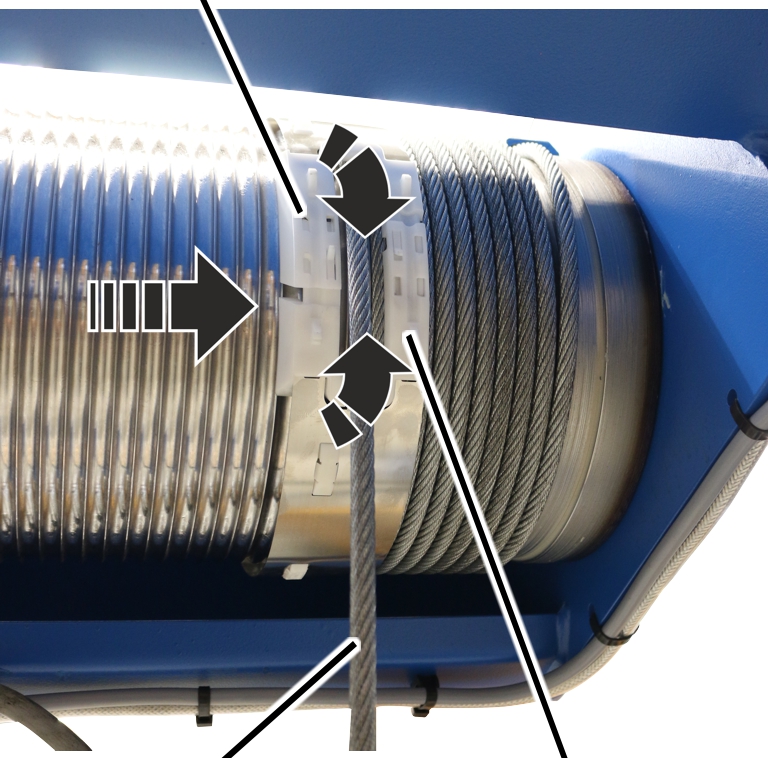
Rope guide runner |
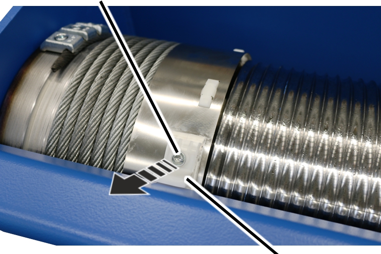
Unscrew the rope guide
runner.
|
Rope guide ring |
| |
|
| ||
|
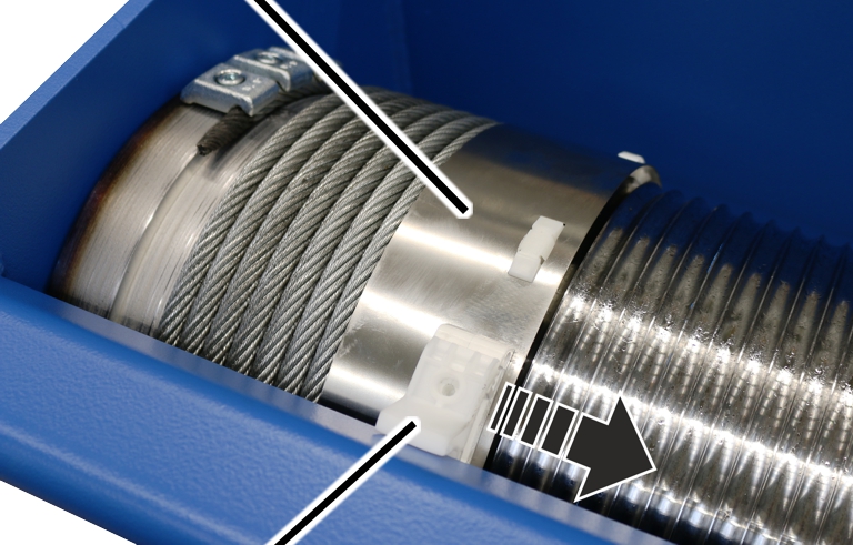
Rope guide runner |
| |
Push the rope guide runner away
to one side of the rope guide ring.
● The rope guide ring can now be turned freely on the cable drum.
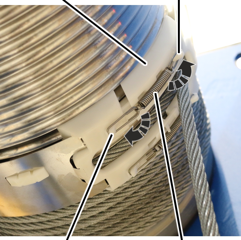
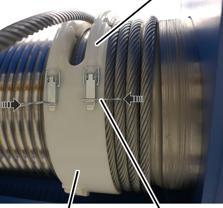
On a wire rope hoist with hoist drive GM 5000, the cable guide consists of a plate, guide elements, edge protection and tension springs.
|
Edge protection |
Catch |
|
| |
|
Catch |
Tension spring |
Release the tension springs from
the catches.
|
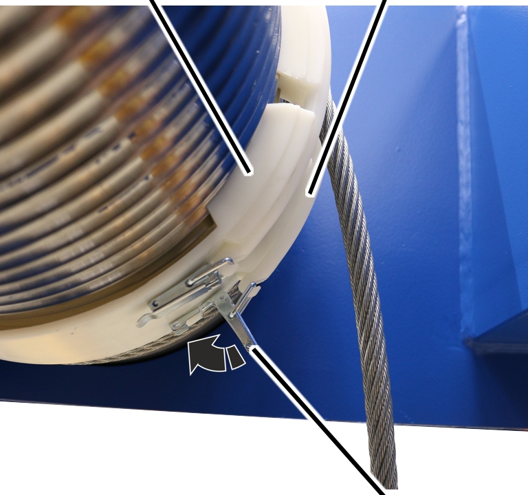
Edge protection A |
|
|
| |
|
Wire rope |
Edge protection B |
Pull edge protections A and B
apart.
Pull the cable guide off the
cable drum.
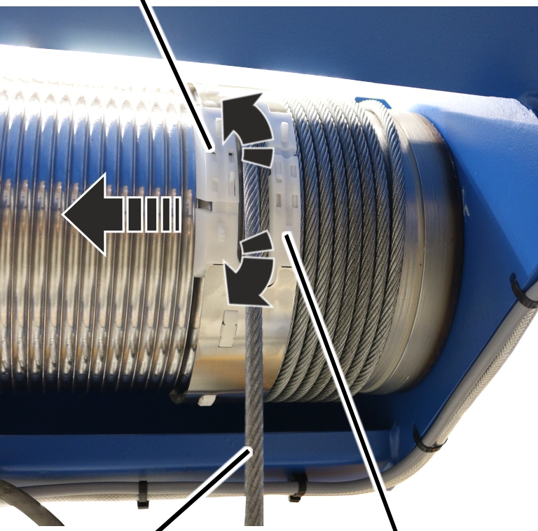
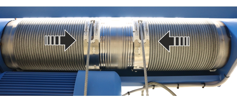
On a wire rope hoist with hoist drive GM 7000, the cable guide consists of a rope guide ring with clamping elements.
|
|
Clamping element |
|
| |
|
Rope guide ring |
Spring cotter |
Pull the spring cotter out of
the clamping elements on the rope guide ring.
|
Rope guide ring |
Clamping element |
|
| |
|
|
Tension lever |
Open and release the tension
lever of the clamping element on the rope guide ring.
|
Cable drum |
Clamping element |
|
| |
|
Wire rope |
Rope guide ring |
Pull the rope guide ring with
clamping elements from the cable drum.
On both sides of the cable drum:
|
Fillister-head screw |
Cable drum |
|
| |
|
End clamp |
Wire rope |
Allow the wire rope to run off
the cable drum using the motor.
Release end clamps.
Completely remove the wire rope
from the cable drum.
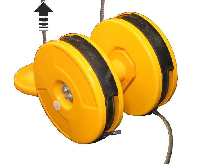
The rope guard in the bottom block will be damaged if the wire rope is pulled along the rope guard quickly to remove it from the bottom block. If the rope guard is to be used again, it should be disassembled beforehand.
ABUS recommends replacing the rope guard together with the wire rope.
|
|
Do not pull the rope guard apart forcefully! If the rope guard halves are pulled apart forcefully during disassembly, the catches will bend. This means the rope guard can no longer be fitted to be functional. Carefully open the rope guard with a screwdriver. |
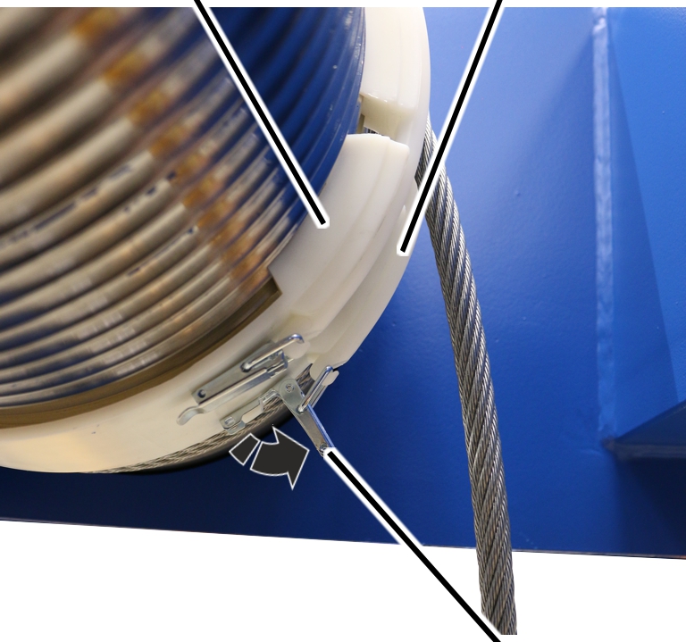
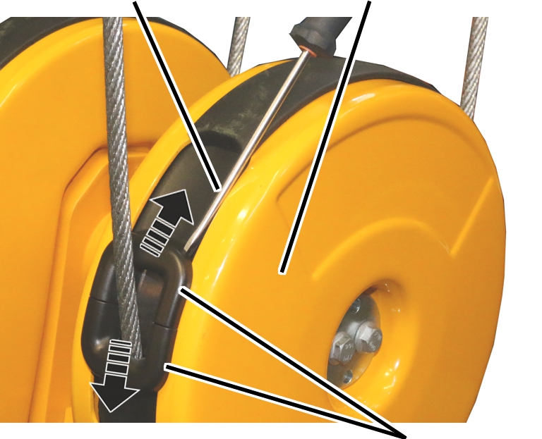
On all openings on the bottom block:
|
Screwdriver |
Bottom block cover |
|
| |
|
|
Rope guard |
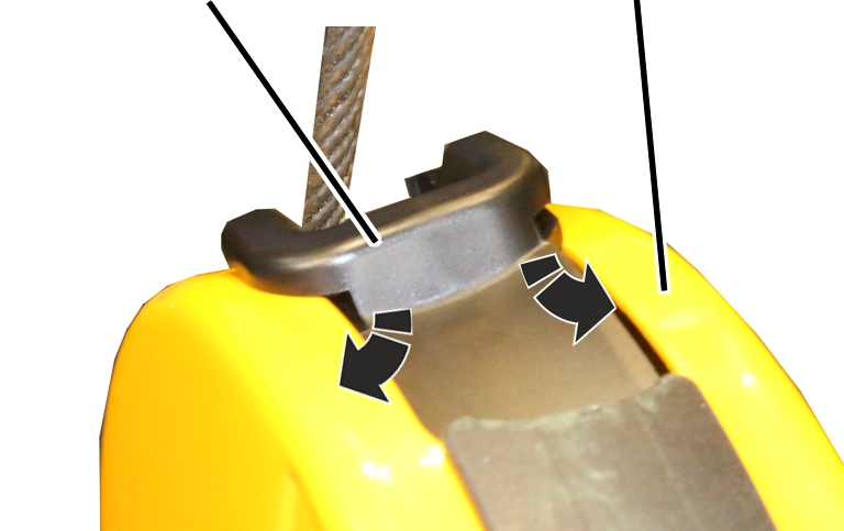
Insert the screwdriver laterally
between the rope guard and bottom block cover as shown in the figure.
Use the screwdriver to unhook
the load hooks on the left and right of the rope guard at the same time.
Pull the rope guard (2x) apart
and remove it from the bottom block.
|
|
Fit the bottom block.
Pull the wire rope out of the
bottom block.
Clean the cable drum.
|
|
Lubricate the cable drum from
the start to about the 8th or 10th turn on both sides.
Lubricate the cable drum in the
middle behind or in front of the last turn.
Lubricant: “Molykote PG-75”. For details, see Lubricants.
|
|
Lubricate the cable drum from
both sides behind the 8th or 10th turn up to the last turn in the centre.
Lubricant: “Chainlife S”. For details, see Lubricants.
|
|
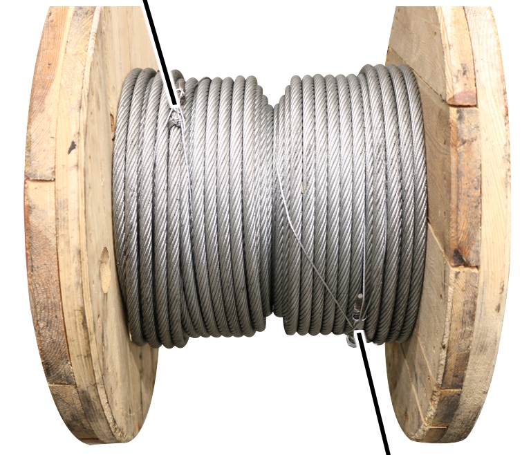
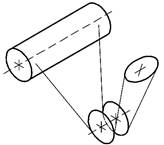
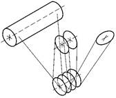
Roll out the wire rope without twisting it! The wire rope will bend and become damaged if it is unrolled incorrectly. Do not pull the wire rope upwards away from a horizontally-lying ring. Unroll the ring so it is vertically upright instead, and allow the wire rope to run onto the cable drum in the same direction as it was rolled onto the ring. |
Note
The wire rope is completely wound up. When unrolling the wire rope make sure the wire rope is unrolled evenly so that later, the wire rope marking lies centrally in the groove of the deflection roller and the wire rope is wound up onto the cable drum evenly.
|
End of the wire rope |
|
|
| |
|
|
End of the wire rope |
Unroll the wire rope evenly and
without twisting it.
|
|
End of the wire rope |
|
| |
|
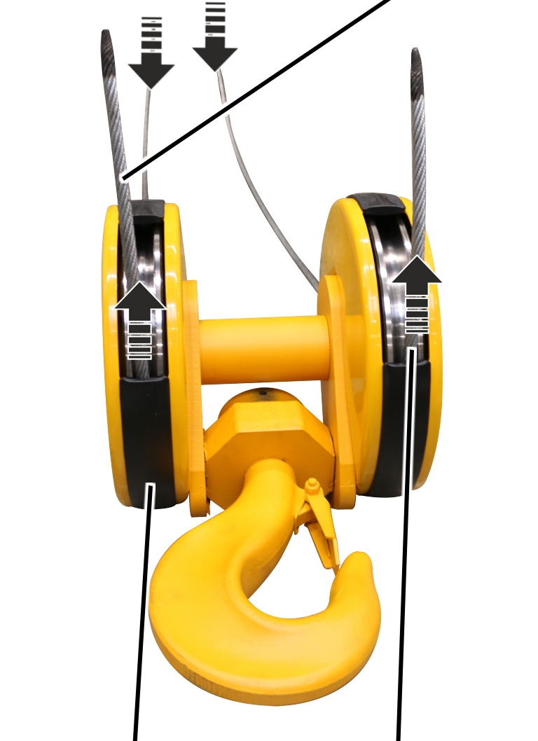
Bottom block |
End of the wire rope |
Pull both ends of the wire rope
through the bottom block without twisting the wire rope.
|
|
|
|
Reeving 4/2 |
Reeving 8/2 |
For reeving 4/2: pull the wire
rope through the bottom block, without twisting it.
For reeving 8/2: pull the wire
rope through the central reels of the bottom block, without twisting it, and
through the reels of the upper block and once again through the outer reels of
the bottom block.
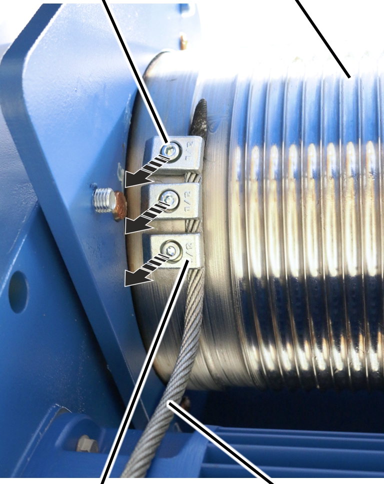
On both sides of the cable drum:
|
Fillister-head screw |
Cable drum |
|
| |
|
End clamp |
Wire rope |
Unroll the wire rope without
twisting it.
Thoroughly clean the
fillister-head screws of the end clamps.
The fillister-head screws were previously bolted with a thread lock coating or a thread lock. The residues must be completely removed before the fillister-head screw may be used again.
The thread lock coating as well as the thread lock are single-use only.
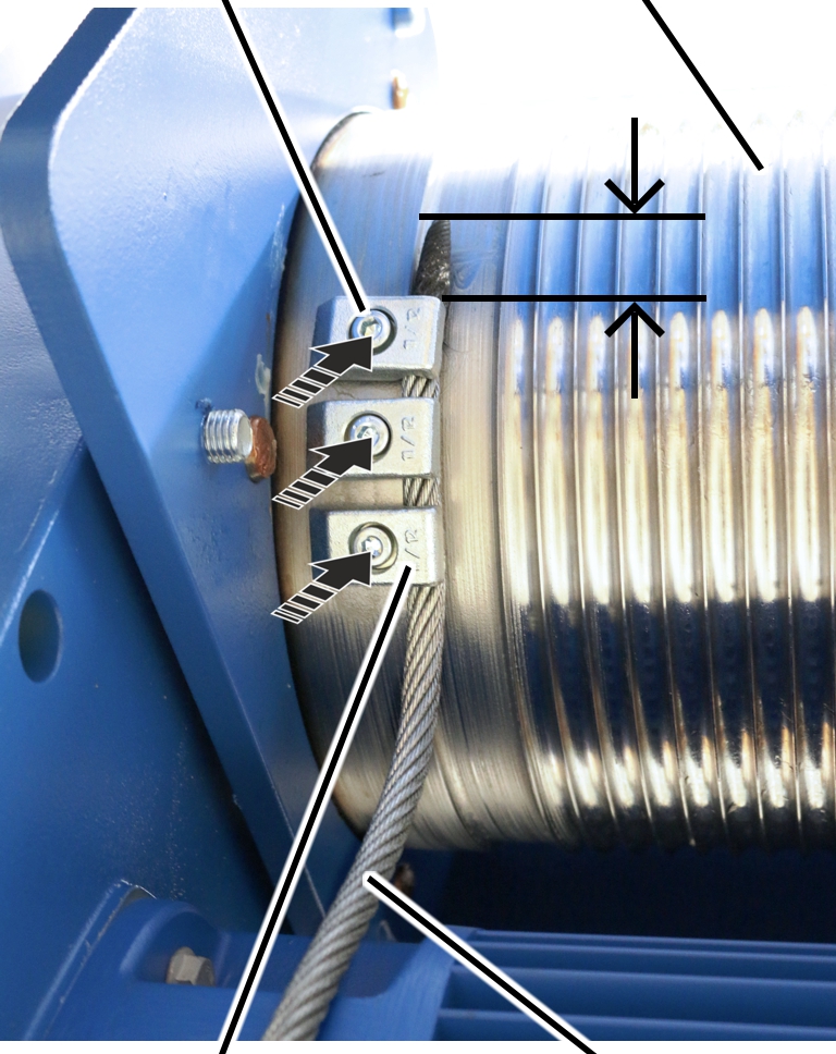
Push the wire rope under the end
clamps far enough that the rope protrusion is about 30 mm.
Tighten the end clamps with
fillister-head screws and secure with (medium strength) thread lock.
|
Size |
Number of end clamps |
Tightening torque |
|
GM 5000 |
3 |
210 Nm |
|
GM 7000 |
3 |
425 Nm |
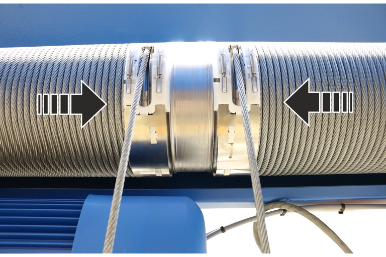
Pull the wire rope taut and use
the motor to wind it onto the cable drum by 6 to 8 turns, ensuring it is taut
and not twisted.
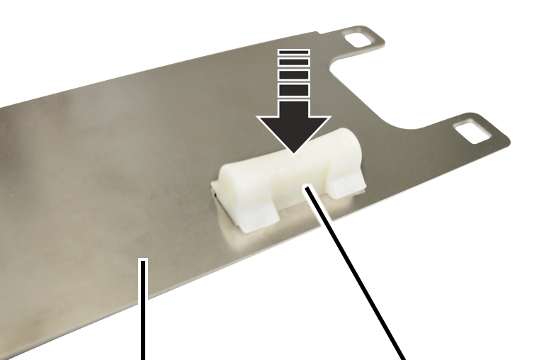
On a wire rope hoist with hoist drive GM 5000, the cable guide consists of a metal plate.
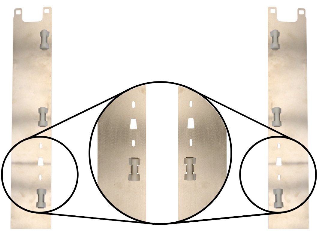
A cable guide for the left side and a cable guide for the right side must be fitted. The holes for the rope guide runner must be on the correct side.
|
|
Note the holes for the rope
guide runner.
|
| |
|
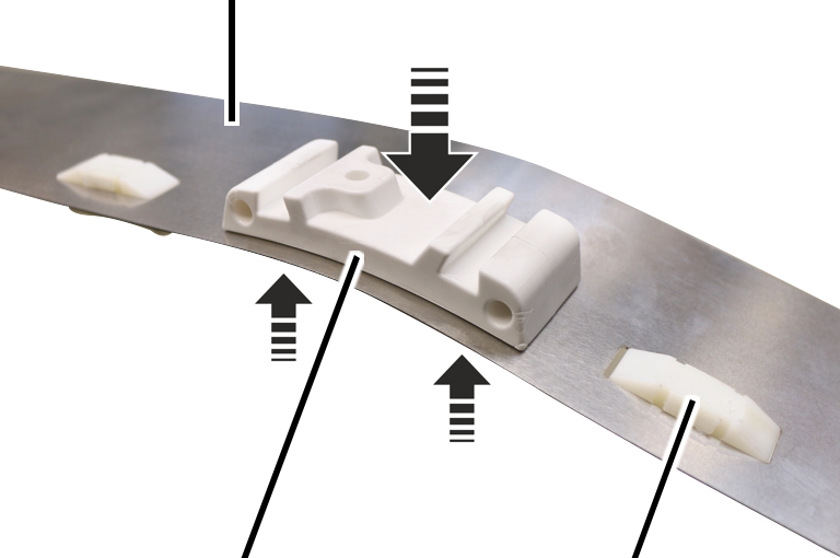
Cable guide |
Guide element |
Press guide elements into cable
guide.
The hooks on the guide elements must engage and fit tightly!
|
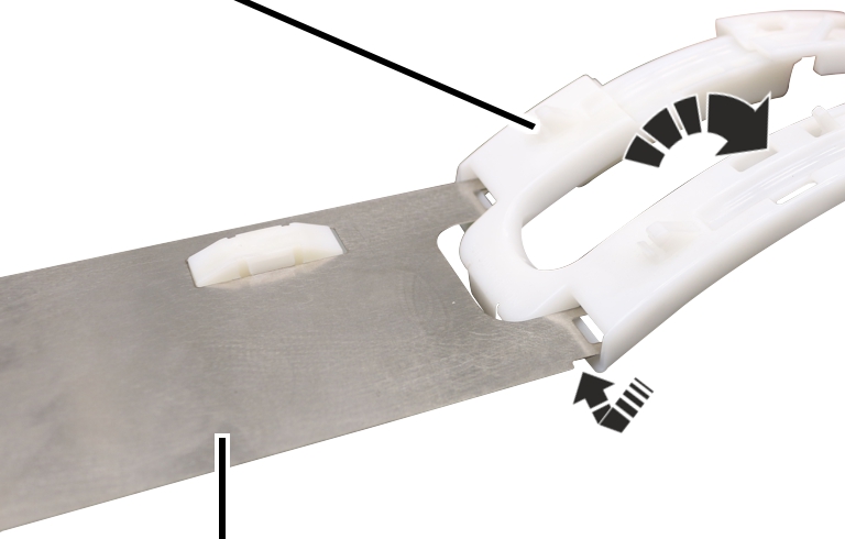
Cable guide |
|
|
| |
|
Rope guide runner adapter |
Guide element |
Screw the rope guide runner
adapter onto both cable guides from the outside. 1.5 Nm.
The thicker side of the guide elements must point inwards.
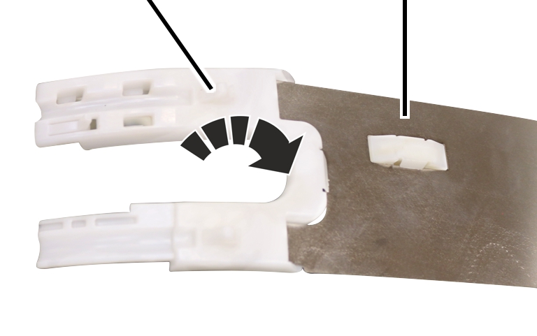
On both sides of the cable guide:
The edge protections are identified by the letters A and B.
|
Edge protection A |
|
|
| |
|
Cable guide |
|
Slide edge protection A onto the
cable guide and engage it.
The rope guide runner adapter must be on the upper side.
|
Edge protection B |
Cable guide |
|
| |
Push edge protection B onto the
other side of the cable guide and engage it.
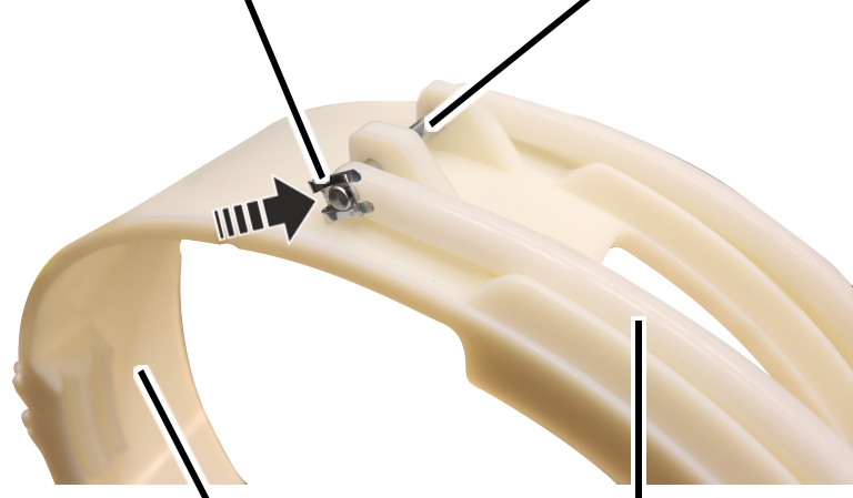
On the cable guide for a wire rope hoist with hoist drive GM 7000, the clamping elements are secured on the rope guide ring using a bolt and a SL safety clip. The eyebolts for tensioning the rope guide ring are located below on the clamping elements.
|
Clamping elements |
Bolt |
|
| |
|
Rope guide ring |
|
 Push the bolt through the clamping elements and the rope guide
ring.
Push the bolt through the clamping elements and the rope guide
ring.
|
SL safety clip |
Bolt |
|
| |
|
Rope guide ring |
Clamping element |
Push the SL safety clip onto the
bolt.
Grease the groove of the rope guide ring from the inside.
Lubricant: “Molykote PG-75”. For details, see Lubricants.
|
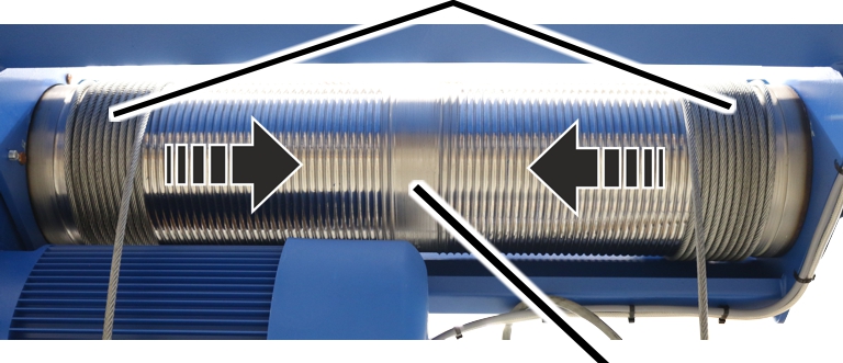
8 to 10 turns | |
|
| |
|
|
Cable drum |
Pull the wire rope taut and use the motor to wind it onto the cable
drum by 8 to 10 turns, ensuring it is taut and not twisted.
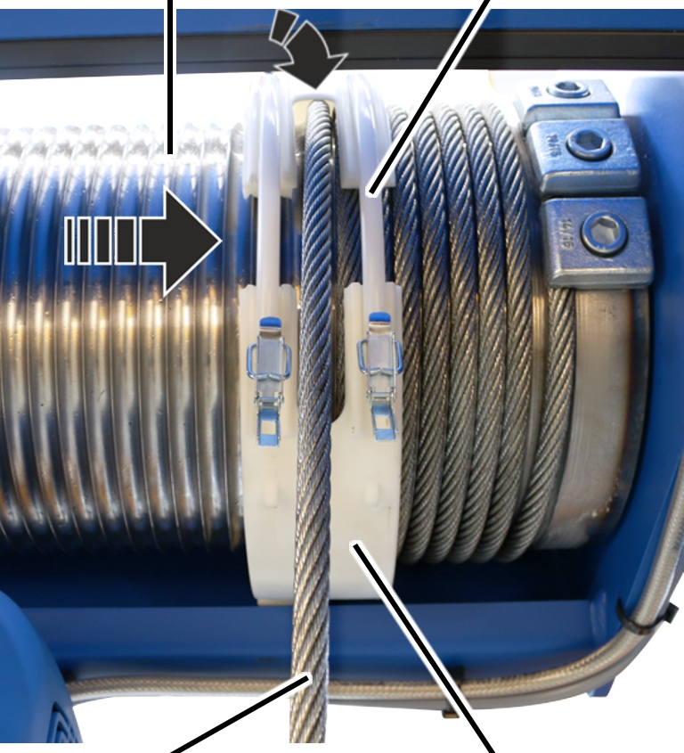
On a wire rope hoist with hoist drive GM 5000, the cable guide consists of a plate, guide elements, edge protection and tension springs.
On both sides of the cable drum:
Make sure when assembling the cable guides, that there is one cable guide for the left side and one for the right side.
|
|
Cable guide |
|
| |
|
Cable drum |
10 windings |
Push the cable guide around the cable drum.
The guide elements must point inwards.
|
Edge protection A |
|
|
| |
|
Wire rope |
Edge protection B |
Position the wire rope between edge protection A and edge protection
B.
 Push edge protections A and B together.
Both ends of the rope guide ring must lie in the same groove of the cable drum. The ends of the rope guide ring must be aligned.
The edge protections must engage with each other.
|
Edge protection |
Catch |
|
| |
|
Catch |
Tension spring |
Attach the tension springs in the upper and lower catches of edge
protection A and B such that the rope guide ring rests firmly on the wire rope,
but can still turn freely.
On a wire rope hoist with hoist drive GM 7000, the cable guide consists of a rope guide ring with clamping elements.
On both sides of the cable drum:
Make sure when assembling the cable guides, that there is one cable guide for the left side and one for the right side.
|
Cable drum |
Clamping element |
|
| |
|
Wire rope |
Rope guide ring |
Pull the rope guide ring with clamping elements onto the cable
drum.
Position the wire rope between the clamping elements.
Check that both ends of the rope guide ring lie in the same groove of
the cable drum.
The ends of the rope guide ring must be aligned.
|
Rope guide ring |
Clamping element |
|
| |
|
|
Tension lever |
Insert the tension lever on the clamping elements into the rope guide
ring and close it.
If necessary:
Open the tension lever again and adjust the rope guide ring with the
eyebolts so that the rope guide ring rests securely on the wire rope but can
still be rotated.
|
|
Clamping element |
|
| |
|
Rope guide ring |
Spring cotter |
Push the spring cotter into the tension lever of the clamping
elements.
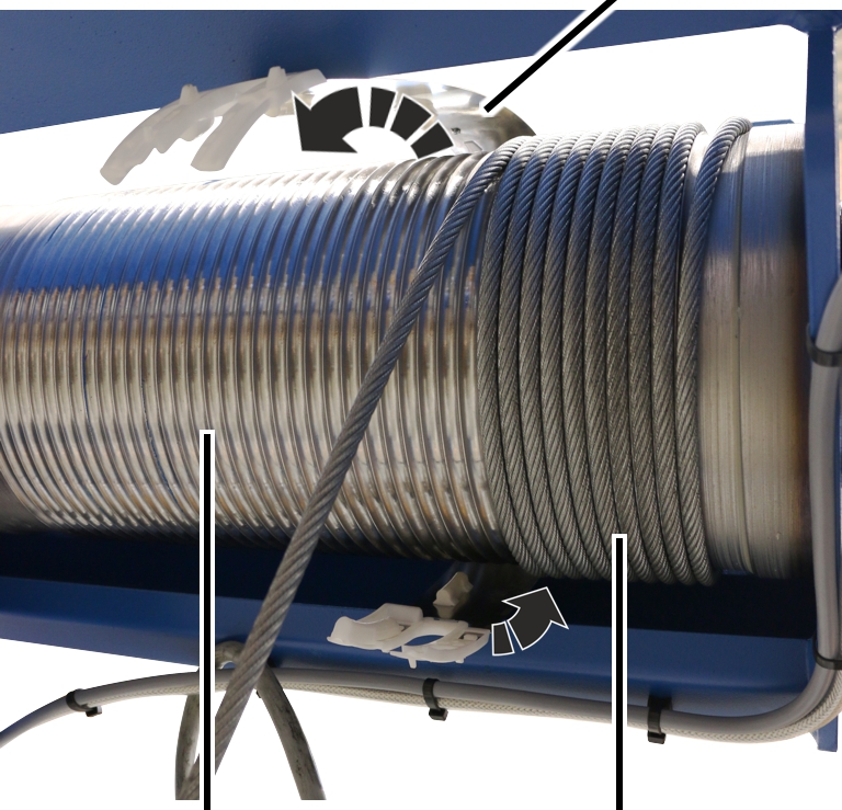
On both sides of the cable drum:
|
Rope guide ring |
| |
|
| ||
|
Rope guide runner |
| |
Put the rope guide runner on the drum housing and push it laterally
into the rope guide ring.
|
Self-tapping screw |
|
|
| |
|
|
Rope guide runner |
Screw on the rope guide runner with the self-tapping screw M6x16.
5 Nm.
|
|
Use the motor to wind up the wire rope.
The wire rope must not be completely wound up.
|
Marking |
|
|
| |
|
|
Deflection roller |
Lay the wire rope into the groove of the deflection roller with the
marking in the centre.
|
Deflection roller crosshead |
Measurement bolt | |
|
| ||
|
Deflection roller |
Wire rope | |
Push the deflection roller with the wire rope into the deflection
roller crosshead.
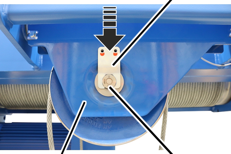
Push the measurement bolt through the deflection roller and the
deflection roller crosshead.
The arrow on the measurement bolt must point downward!
|
|
Mount |
|
| |
|
Deflection roller crosshead |
Measurement bolt |
Slide the mount onto the measurement bolt.
|
|
Rib screw M10x20 |
|
| |
|
Mount |
|
Screw in the mount with the rib screws M10x20. 75 Nm.
Secure the rib screws with screw lock lacquer.
On all openings on the bottom block:
|
|
Connecting profile |
|
| |
|
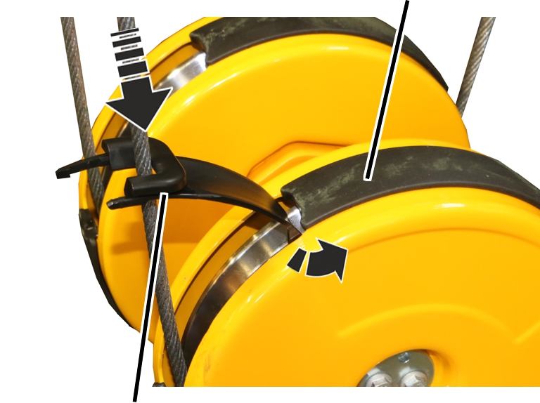
Rope guard |
|
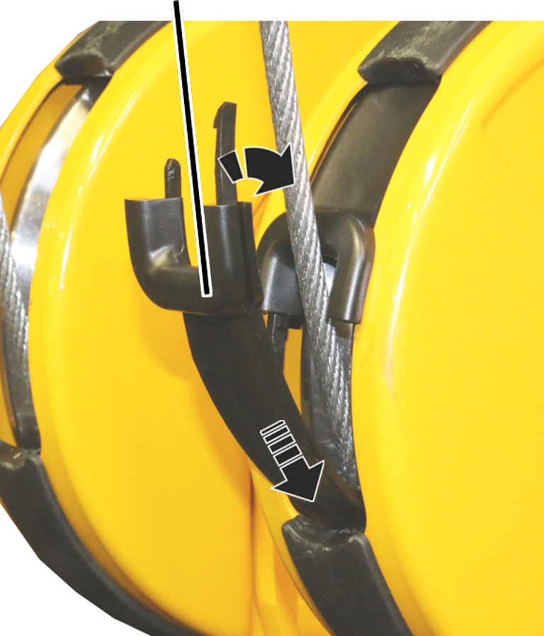
Hold the rope guard on the wire rope as shown in the figure.
Push the rope guard down along the wire rope with the front fork and
bring the rear end under the connecting profile.
|
Rope guard |
Bottom block cover |
|
| |
First push the rope guard on the side with the short bracket into the
bottom block cover.
Then push the rope guard on the side with the long bracket into the
bottom block cover.
|
Rope guard |
|
|
| |
Push the second rope guard at the bottom into the connecting
profile.
Push the rope guard downwards behind the connecting profile and
attach it above on the wire rope.
First push the rope guard on the side with the short bracket into the
bottom block cover.
Then push the rope guard on the side with the long bracket into the
bottom block cover.
|
|
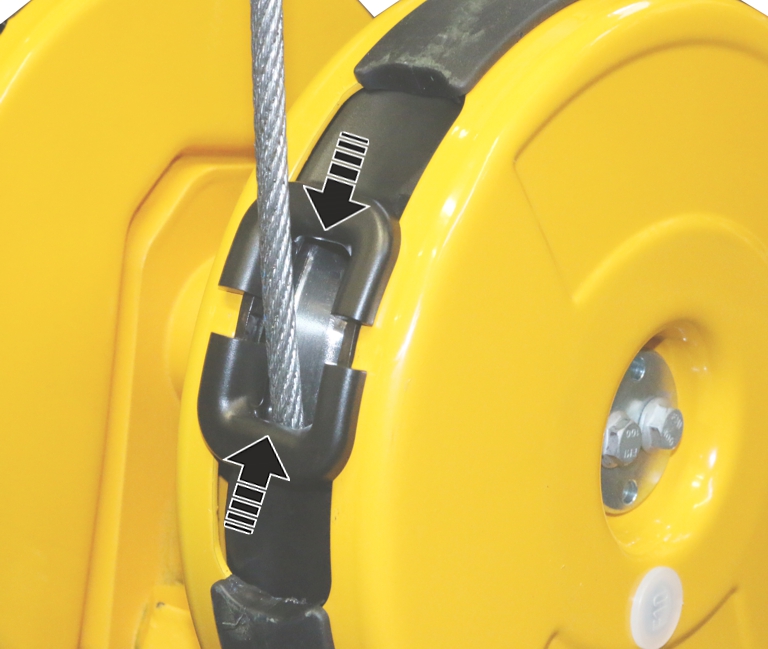
Connect the brackets of the rope guards (2x) and push them
together.
● A snapping sound can be heard.
|
|
Use the motor to wind up the wire rope completely.
If ABUControl is installed for the wire rope hoist, refer to the product manual “ABUControl”, section “Exchanging the wire rope” to conclude the rope change.
Further steps are then described in this product manual.
Move the load hooks to the position you noted previously.
|
Shaft |
Bearing flange |
|
| |
Open the housing cover of the hoist limit switch enclosure on the
cable drum.
Rotate the shaft of the gear limit switch so that it matches the
elongated hole in the bearing flange of the cable drum.
|
|
Plastic screws B6, 3x25 |
|
| |
|
Cam switch PCB |
|
Insert the gear limit switch with the shaft in the elongated hole on
the bearing flange and guide it onto the two pins.
Screw the gear limit switch tight with the plastic screws B6, 3x25.
2.5 Nm.
Plug in the connector of the connection cable on the cam switch
PCB.
Close the housing cover.
If the switching points have moved:
Normally, the adjustment of the hoist limit switch after replacing the wire rope can in many cases be omitted, since the position of the load hook was previously measured and then travelled to again. In special cases (e.g. if the wire rope is severely damaged or has been incorrectly rolled onto the cable drum), the switching points may need to be readjusted.
Reset switching points for the bottom hoist limiter, the top hoist
limiter and the backup limiter.
With ABUS electrics 3 with contactor control: see product manual “ABUS gear limit switch”.
With ABUS electrics 3 with ABULiner: see product manual “Frequency converter control of the lifting speed for ABUS electrics 3”.