If the crane is not working or
functions other than as expected, a malfunction of the frequency converter or on
the LIS-SV may be the cause.
|

|
Danger from electric shock!
Even after the emergency stop button has been
pressed, life-threatening high voltages are present in the hoist panel and
frequency converter.
Before working on the crane, disconnect the power
line and wait at least four minutes until the voltage has dissipated.
Only trained electricians should work on the crane
electrical system! |
If the ABULiner switches off after a malfunction, it must be
reset.
 Press the emergency stop
switch.
Press the emergency stop
switch.
● The crane
brakes immediately; the load hook halts.
Wait about one minute.
Unlock the emergency stop
switch.
● The ABULiner is restarted.
Error in
frequency converter
Only with Danfoss frequency
converter
In the event of malfunctions on the ABULiner:
Malfunctions on the ABULiner can be caused by the frequency
converter.
The brake of the hoist motor is wired such that, even in the
event of an error, braking is ensured and the wire rope hoist stops.
Error codes and messages are read out by external diagnostic
devices. Contact ABUS Service. See ABUS Service.
Only with Siemens frequency
converter
In the event of malfunctions on the ABULiner:
Malfunctions on the ABULiner can be caused by the frequency
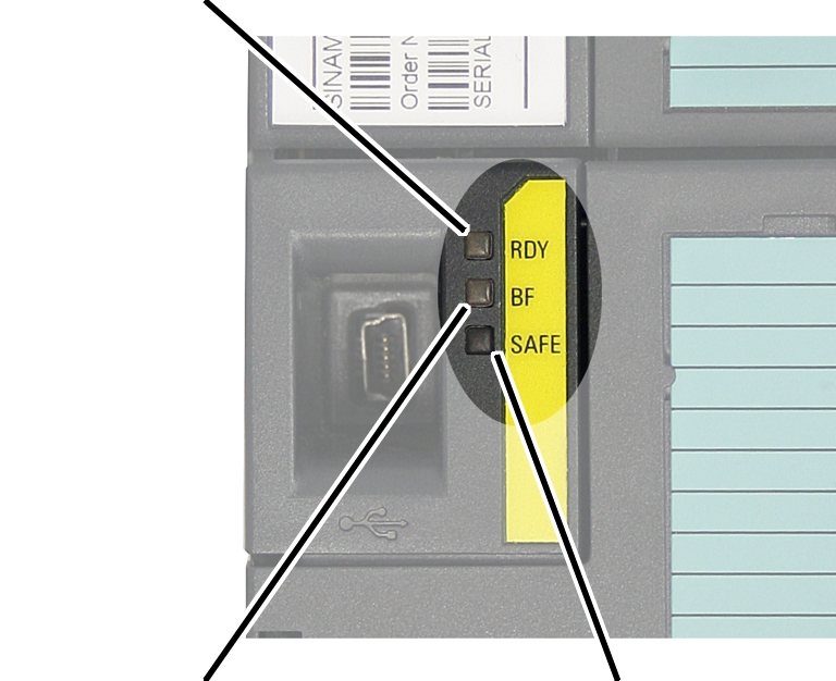
converter. The frequency converter has three LEDs. Two of these light up or
flash in the event of errors.
The brake of the hoist motor is wired such that, even in the
event of an error, braking is ensured and the wire rope hoist stops.
|
LED for
ready or malfunction |
|
|
|
|
LED not used for ABULiner |
LED for safety input |
● The LED for
ready or malfunction lights up green or flashes red.
● The LED for
the safety input is lights up or flashes yellow (fast or slowly).
|
LED |
Meaning |
|
RDY (ready or malfunction) lights up green |
No error has occurred. |
|
RDY (ready or malfunction) flashes red |
An error has occurred in the frequency
converter. |
|
SAFE (safety input) lights up yellow |
Normal operating mode.
The power unit of the frequency converter and the
relay “release signal brake” are released.
The main contactor is switched. |
|
SAFE (safety input) flashes yellow slowly |
The power unit of the frequency converter and the
relay “release signal brake” are disabled.
The main contactor is switched off. |
|
SAFE (safety input) flashes yellow quickly |
An error has occurred in the frequency converter or
in the wiring of the safety inputs. |
Only with the Schneider
frequency converter
In the event of ATV340 frequency converter malfunctions:
Malfunctions on the ABULiner can be caused by the frequency
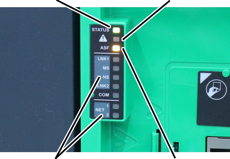
converter. The frequency converter has numerous LEDs. Three of these light up or
flash in the event of errors.
The brake of the hoist motor is wired such that, even in the
event of an error, braking is ensured and the wire rope hoist stops.
|
LED for
status |
LED
warning/error |
|
|
|
LED not used for ABULiner |
LED for safety function |
|
|
|
● The LED for
the status flashes or lights up green.
● The LED for
warning/error lights up or flashes red.
● The "ASF"
LED lights up yellow.
|
LED |
Colour and status |
Meaning |
|
Status |
Off |
The frequency converter is switched off |
|
|
Flashes green |
The frequency converter is not operating, but it is
ready to start. |
|
|
Flashes green quickly |
The frequency converter brakes or
accelerates. |
|
|
Lights up green |
The frequency converter is in operation. |
|
Warning/
error |
Flashes red slowly |
Warning |
|
|
Lights up red |
Fault |
|
ASF |
Lights up yellow |
The safety function has been
triggered. |
In the event of ATV320 frequency converter malfunctions:
Malfunctions on the ABULiner can be caused by the frequency
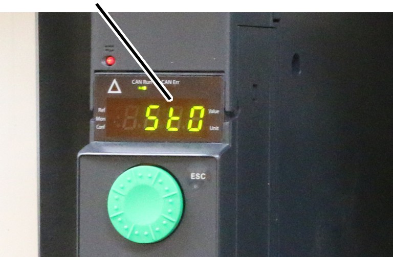
converter. The frequency converter has a display which shows the error codes.
The brake of the hoist motor is wired such that, even in the
event of an error, braking is ensured and the wire rope hoist stops.
|
Display
with error codes |
|
|
|
● The display
of the frequency converter shows an error code.
|
Error code |
Meaning |
|
STO |
"Safe Torque Off"
No mains voltage at the input
Main contactor K 1.1 not tightened |
|
RDY |
"Ready"
The frequency converter is ready for
operation |
|
CFF |
"Incorrect configuration"
Contact ABUS Service |
|
CFI |
"Missing configuration"
Contact ABUS Service |
|
OCF |
"Overcurrent"
Inertia or load too high, possibly due to mechanical
blocking of the hoist motor.
Check whether the brake opens correctly; reduce the
load if necessary.
If the error also occurs at zero load, check the
hoist motor and contact ABUS Service. |
|
ObF |
"Energy surplus when braking"
Excessive braking or driving load.
During lowering: Check error LED on the power
feedback unit. |
|
OSF |
"Overvoltage"
Check the input phases. |
|
USF |
"Undervoltage"
Check the input phases. |
|
SCF1..3 |
"Short circuit or earth fault at the frequency
converter output"
Check the frequency converter output and motor
connection.
Strong leakage current against the protective
conductor at the frequency converter output when connecting several
motors. |
|
NLP |
"No voltage at the input" |
|
NST |
"Free runout"
A control signal was present when the frequency
converter started.
Release the lifting/lowering and wait until the
"RDY" frequency converter is displayed. |
If there are malfunctions on the power feedback unit:
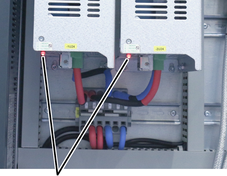
Malfunctions on the ABULiner can be caused by the power
feedback unit. The power feedback unit has an LED which displays the operating
status.
|
|
|
LED for status and error display |
|
● The LED
lights up or flashes red.
|
Status LED |
Meaning |
|
off |
Device is switched off |
|
on |
Standby |
|
flashes continuously |
Device supplies energy |
|
flashes 1 times |
Input phase missing |
|
flashes 2 times |
Undervoltage |
|
flashes 3 times |
Excess temperature |
|
flashes 4 times |
Overvoltage |
|
flashes 5 times |
Overcurrent |
|
flashes 6 times |
Internal error |
LIS-SV error
codes
In the event of malfunctions on the ABULiner:
Malfunctions on the ABULiner can be displayed by error codes
on the LIS-SV.
The brake of the hoist motor is
wired such that, even in the event of an error, braking is ensured and the crane
stops.
|
Error
code |
|
|
|
● The LIS-SV
display shows an error code.
● The main
contactor is switched off, the entire crane is at a standstill.
● After about
one minute, the main contactor is automatically switched back on.
Before operating the crane
again, be sure to identify and eliminate the error.
Note:
The LIS-SV is automatically reset after a few seconds
(depending on the error). An error at the frequency converter is not reset this
way. Usually, the emergency stop button should therefore be pressed to reset
after an error. See Resetting after a
malfunction.
|
Code |
Reset
after |
Error |
Possible
cause |
Eliminating the
error |
|
E_Fu |
5 s |
More than 15% more
impulses from the encoder than permitted were counted in the limit switch
range. |
Hoist motor does not
stop. |
Contact ABUS Service.
See ABUS Service. |
|
|
|
|
Control unit is
defective. |
|
|
|
Impulses in the limit
switch range can no longer be correctly counted. |
The load hook was in
the limit switch range when the parameter level was called
up. |
|
EFu1 |
13 s |
With the “Lift”
button pressed, the cable drum turned in the “Lower”
direction. |
Hoist motor is
faulty. |
Check the hoist
motor. |
|
|
|
|
Error in the
connection of the ABULiner. |
Check connection. See
Assignment of terminal blocks and pin
multipoint connectors. |
|
|
|
|
The load slips
through. |
Contact ABUS Service.
See ABUS
Service. |
|
|
|
The cable drum turns
in the “Lift” direction, but +12 V is not present at input
I1.. |
Encoder is
faulty. |
Check
encoder. |
|
|
|
|
Error in the
connection of the ABULiner. |
Check connection. See
Assignment of terminal blocks and pin
multipoint connectors. |
|
EFu2 |
7 s |
The permissible speed
of the cable drum was exceeded by more than 20%. |
Incorrect setting on
the frequency converter. |
Check parameters.
|
|
|
|
|
Hoist motor is
faulty. |
Check the hoist
motor. |
|
|
|
|
Error in speed
analysis |
Check the signals
from the encoder. |
|
|
|
|
|
Check the parameters
of the LIS-SV. |
|
EFu4 |
67 s |
Without the buttons
“Lift/Lower” being pressed, a the switching of a brake contactor was
detected (through input RxD on the LIS-SV) |
Error in the
connection of the ABULiner. |
Check connection. See
Assignment of terminal blocks and pin
multipoint connectors. |
|
|
|
|
|
Check connection to
brake contactor K26.3. See Assignment of terminal blocks and pin
multipoint connectors. |
|
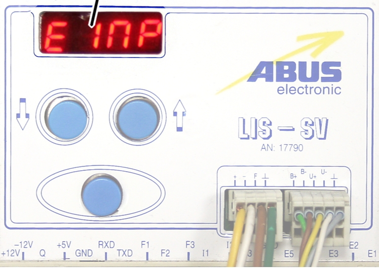
EIMP |
67 s |
With the “Lift/Lower” button pressed, no impulses
were received from the encoder. |
Encoder is faulty. |
Check encoder. |
|
|
|
|
The cable drum does not turn with the brake
released. |
Check
connection. See Assignment of terminal blocks and pin
multipoint connectors. |
|
|
|
|
|
Check the hoist motor. |
|
|
|
|
Connection cable of encoder is damaged. |
Check the connection cable. |
|
|
|
|
The LIS-SV is faulty. |
Contact ABUS Service. See ABUS Service. |
|
(without) |
|
No value can be set for parameter 5.11. |
A value has been set for parameter 3.0. |
Set parameter 3.0 to zero. See Activating/deactivating the
LIS-SV for the ABULiner. |
|
- - - -
(bar in the display does not change) |
|
A control signal (lift/lower) is present, the
corresponding output is switched but the brake is not released. |
Brake contactor K26.3 does not switch. |
Check brake contactor K26.3 and activation. See Assignment of terminal blocks and pin
multipoint connectors. |
|
|
|
|
Input RxD on the LIS-SV receives no signal. |
Check
connection. See Assignment of terminal blocks and pin
multipoint connectors. |
|
- - H2 |
|
With two wire rope hoists: Brake contactor K26.3
does not switch on wire rope hoist 2 (a signal is present at input I3 on
the LIS-SV) |
Error on wire rope hoist 2. |
Check rope hoist 2.
To check wire rope hoist 2, switch off joint
operation (wire rope hoist 1 + 2) on the pendant control.
|
Additional
errors