The wire rope hoist
has a gear limit switch with at least three switching points. The backup limiter
and the top hoist limiter are set at the factory. The bottom hoist limiter was
set during assembly.
After wire rope replacement or repairs, the backup limiter
and top hoist limiter may have to be reset.
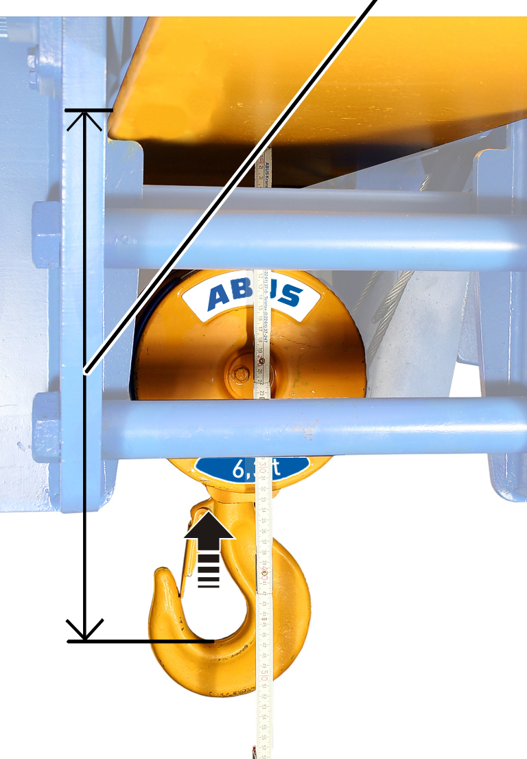
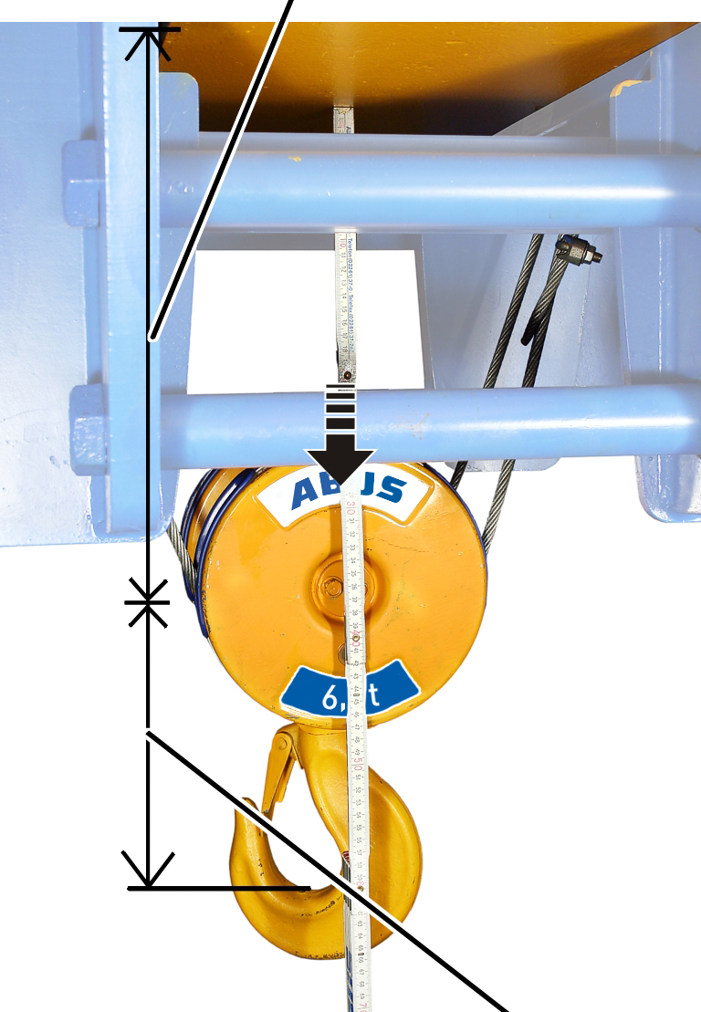
Determining the
hook headroom (C-size) for the backup limiter
─ The hook
headroom is always the distance between the lower edge of the wheel on the wire
rope hoist and the inner edge of the load hook.
─ The hook
headroom is the absolutely uppermost position up to which the load hook may move
without damaging the wire rope.
─ The hook
headroom always refers to a standard series load hook. In the case of larger or
smaller load hooks, see the wire rope data sheet for details of the hook
headroom.
|

|
Danger from falling suspended load!
In certain situations it can be necessary to
enlarge the hook headroom to enable the load hook to brake more quickly
(e.g. so that a crosshead cannot crash under the main girder or lifting
tackle on the main girder are not broken open).
Always carry out and heed a hazard analysis on
site! |
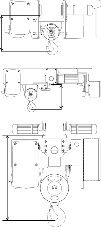
Hook headroom for wire rope hoists of overhead
travelling cranes: types E, S and U.
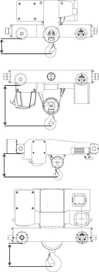
Hook headroom for wire rope hoists of overhead
travelling cranes: types D, DA, DQA and Z.
 Read the hook headroom
(C-size) from the table.
Read the hook headroom
(C-size) from the table.
|
Type |
Size |
Reeving |
Track gauge [mm] |
Hook headroom [mm] |
|
E |
800 |
4/1 |
Up to 300 |
400 |
|
E |
1000 |
4/1 |
Up to 300 |
500 |
|
E |
1000 |
2/1 |
Up to 300 |
567 |
|
E |
2000 |
4/1 |
Up to 300 |
500 |
|
E |
2000 |
2/1 |
Up to 300 |
580 |
|
E |
3000 |
4/1 |
Up to 300 |
580 |
|
E |
3000 |
2/1 |
Up to 300 |
664 |
|
E |
5000 |
2/1 |
Up to 350 |
830 |
|
E |
5000 |
4/1 |
Up to 350 |
825 |
|
E |
6000 |
2/1 |
Up to 350 |
830 |
Table: Hook headroom for wire rope hoists of type E.
With larger hoist spans please heed the following!
|
Type |
Size |
Reeving |
Hook headroom [mm] |
|
S |
800 |
4/1 |
343 |
|
S |
1000 |
4/1 |
420 |
|
S |
2000 |
4/1 |
440 |
|
S |
3000 |
2/1 |
699 |
|
S |
3000 |
4/1 |
550 |
Table: Hook headroom for wire rope hoists of type
S
|
Type |
Size |
Reeving |
Hook headroom [mm] |
|
U |
5000 |
4/1 |
1132 |
|
U |
6000 |
2/1 |
1256 |
|
U |
6000 |
4/1 |
1241 |
|
U |
7000 |
2/1 |
1615 |
Table: Hook headroom for wire rope hoists of type
U
|
Type |
Size |
Reeving |
Track gauge [mm] |
Hook headroom [mm] |
|
D |
800 |
4/1 |
|
144 |
|
D |
1000 |
4/1 |
|
195 |
|
D |
2000 |
2/1 |
|
295 |
|
D |
2000 |
4/1 |
|
215 |
|
D |
3000 |
2/1 |
|
315 |
|
D |
3000 |
4/1 |
|
260 |
|
D |
3000 |
4/2 |
|
250 |
|
D160 |
3000 |
6/1 |
|
469 |
|
D200 |
3000 |
6/1 |
|
429 |
|
D |
5000 |
2/1 |
|
440 |
|
D |
5000 |
4/1 |
|
385 |
|
D |
5000 |
4/2 |
|
320 |
|
D200 |
5000 |
6/1 |
|
611 |
|
D280 |
5000 |
6/1 |
|
606 |
|
D |
6000 |
2/1 |
|
520 |
|
D |
6000 |
4/1 |
|
267 |
|
D |
6000 |
6/1 |
|
606 |
|
D |
7000 |
2/1 |
|
572 |
|
D |
7000 |
4/1 |
|
501 |
|
D |
7000 |
6/1 |
to 2000 |
717 |
|
D |
7000 |
6/1 |
From 2000 |
897 |
|
D |
7000 |
4/2 |
|
236 |
|
D |
7000 |
8/2 |
|
516 |
Table: Hook headroom for wire rope hoists of type
D
|
Type |
Size |
Reeving |
Hook headroom [mm] |
|
DA |
800 |
4/1 |
429 |
|
DA |
1000 |
4/1 |
520 |
|
DA |
2000 |
2/1 |
621 |
|
DA |
2000 |
4/1 |
540 |
|
DA |
3000 |
2/1 |
700 |
|
DA |
3000 |
4/1 |
620 |
|
DA |
3000 |
6/1 |
853 |
|
DA |
5000 |
2/1 |
825 |
|
DA |
5000 |
4/1 |
813 |
|
DA160 |
6000 |
2/1 |
949 |
|
DA200 |
6000 |
4/1 |
470 |
|
DA280 |
6000 |
4/1 |
832 |
|
DA280 |
6000 |
6/1 |
1068 |
|
DA200 |
7000 |
2/1 |
1284 |
|
DA |
7000 |
4/1 |
913 |
|
DA |
7000 |
6/1 |
1370 |
Table: Hook headroom for wire rope hoists of type
DA
|
Type |
Size |
Reeving |
Hook headroom [mm] |
|
DQA |
2000 |
2/1 |
525 |
|
DQA |
2000 |
4/1 |
445 |
|
DQA |
3000 |
2/1 |
639 |
|
DQA |
3000 |
4/1 |
555 |
|
DQA |
5000 |
2/1 |
810 |
|
DQA |
5000 |
4/1 |
712 |
|
DQA |
6000 |
2/1 |
870 |
|
DQA |
6000 |
4/1 |
745 |
|
DQA350 |
7000 |
4/1 |
970 |
|
DQA400 |
7000 |
4/1 |
998 |
Table: Hook headroom for wire rope hoists of type
DQA
|
Type |
Size |
Reeving |
Track gauge [mm] |
Hook headroom [mm] |
|
Z |
5000 |
4/2 |
|
413 |
|
Z |
5000 |
8/2 |
|
631 |
|
Z |
6000 |
4/2 |
|
414 |
|
Z280 |
6000 |
8/2 |
|
638 |
|
Z350 |
6000 |
8/2 |
|
643 |
|
Z |
7000 |
4/2 |
|
668 |
|
Z |
7000 |
6/2 |
to 2000 |
717 |
|
Z |
7000 |
6/2 |
From 2000 |
897 |
|
Z |
7000 |
8/2 |
|
915 |
|
Z |
7000 |
10/2 |
|
960 |
|
Z |
7000 |
12/2 |
|
1378 |
Table: Hook headroom for wire rope hoists of type
Z
|
Type |
Size |
Reeving |
Hook headroom [mm] |
|
ZA |
5000 |
8/2 |
1195 |
|
ZA280 |
6000 |
8/2 |
1253 |
|
ZA350 |
6000 |
8/2 |
1163 |
|
ZA |
7000 |
6/2 |
1370 |
|
ZA |
7000 |
8/2 |
1430 |
|
ZA |
7000 |
10/2 |
1312 |
Table: Hook headroom for wire rope hoists of type
ZA
Only for wire rope hoist
design E and large tracks
This section only applies to wire rope hoists of the design E
with a larger track gauge than given in the table above.
Calculating
larger hook headroom
The hook headroom has to be enlarged from a certain track
gauge onwards.
 Add the additional
dimension from this table to the hook headroom from the table above.
Add the additional
dimension from this table to the hook headroom from the table above.
|
Track gauge [mm] |
Installation size 800
Reeving 4/1 [mm] |
Installation size 1000
Reeving 2/1 [mm] |
Installation size 1000
Reeving 4/1 [mm] |
Installation size 2000
Reeving 2/1 [mm] |
Installation size 2000
Reeving 4/1 [mm] |
|
300 |
0 |
0 |
0 |
0 |
0 |
|
350 |
49 |
39 |
45 |
43 |
53 |
|
400 |
98 |
78 |
89 |
86 |
106 |
|
450 |
146 |
117 |
134 |
129 |
159 |
|
500 |
195 |
156 |
178 |
172 |
212 |
|
550 |
- |
- |
- |
- |
265 |
|
600 |
- |
- |
- |
- |
318 |
|
650 |
- |
- |
- |
- |
371 |
|
700 |
- |
- |
- |
- |
424 |
|
Track gauge |
Installation size 3000
Reeving 2/1 [mm] |
Installation size 3000
Reeving 4/1 [mm] |
Installation size 5000
Reeving 2/1 [mm] |
Installation size 5000
Reeving 4/1 [mm] |
Installation size 6000
Reeving 2/1 [mm] |
|
300 |
0 |
0 |
- |
- |
- |
|
350 |
62 |
80 |
0 |
0 |
0 |
|
400 |
124 |
160 |
76 |
74 |
76 |
|
450 |
187 |
240 |
152 |
148 |
152 |
|
500 |
249 |
320 |
228 |
222 |
228 |
|
550 |
311 |
401 |
304 |
296 |
304 |
|
600 |
373 |
481 |
380 |
370 |
380 |
|
650 |
435 |
561 |
456 |
444 |
456 |
|
700 |
498 |
641 |
532 |
518 |
532 |
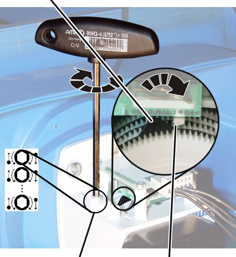
Setting backup
limiter
|
|
Hook
headroom |
|
|
Raise the load hook up to
the hook headroom point.
At the hook headroom previously travelled to:
|
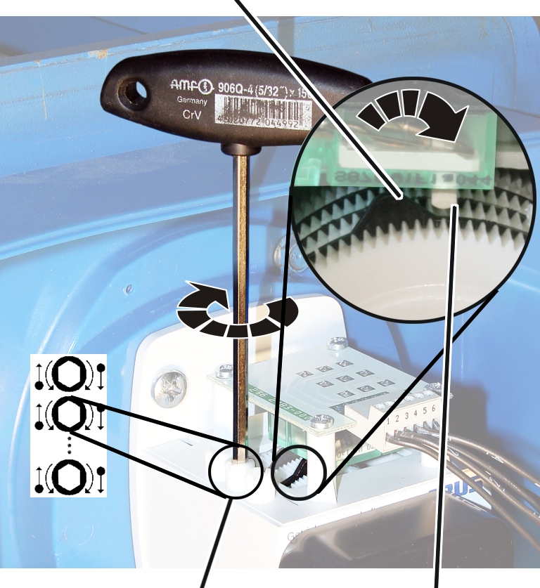
Control
cam |
|
|
|
|
Adjusting screw |
Microswitch |
|
|
|
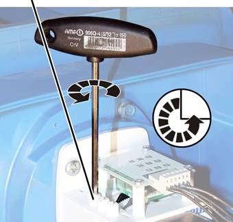
─ The
backup limiter is set with the backmost white adjusting screw.
If necessary: Turn the
adjusting screw until the control cam is to the left of the Microswitch. It
should not be either directly on or to the right of the microswitch.
Turn the adjusting screw
to the right until the control cam presses in a clockwise direction against the
Microswitch and an audible click is heard.
● The main
contactor switches off.
If the switching point is set with a different adjusting
screw than previously specified, this is noted on the wiring diagram.
|
Adjusting screw |
|
|
|
Turn the adjusting screw
three-quarters of a turn to the left.
● The
microswitch switches again; the main contactor switches back on.
Lower the load hook
slightly.
Turn the adjusting screw
three-quarters of a turn back to the right.
Determining and
approaching the braking distance in the limit switch range
Read off the braking
distance from the table.
This braking distance is determined by the LIS-SV and is not
identical to the braking distance during lifting/lowering in normal crane
operation.
|
|
Lifting speed 3000 rpm |
Lifting speed 6000 rpm |
|
Reeving
2/1 and 4/2 |
320 mm |
1280 mm |
|
Reeving
4/1 and 8/2 |
160 mm |
640 mm |
|
Reeving
6/1 and 12/2 |
106 mm |
480 mm |
|
Reeving
10/2 |
128 mm |
512 mm |
|
Reeving
6/2 |
213 mm |
853 mm |
|
Hook headroom |
|
|
|
|
|
Braking
distance |
|
|
|
Move the load hook until
it rests at exactly the braking distance under the hook headroom.
Setting top
hoist limiter
At the hook headroom and braking distance previously travelled
to:
|
Control
cam |
|
|
|
|
Adjusting screw |
Microswitch |
|
|
|
─ The top
hoist limiter is set with the white adjusting screw second from the back.
If necessary: Turn the
adjusting screw until the control cam is to the left of the microswitch. It
should not be either directly on or to the right of the microswitch.
Turn the adjusting screw
to the right until the control cam presses in a clockwise direction against the
Microswitch and an audible click is heard.
If the switching point is set with a different adjusting
screw than previously specified, this is noted on the wiring diagram.
Checking the
setting
Lower the load hook.
Lift the load hook at both
slow and fast lifting speed and check whether it halts at the correct point.
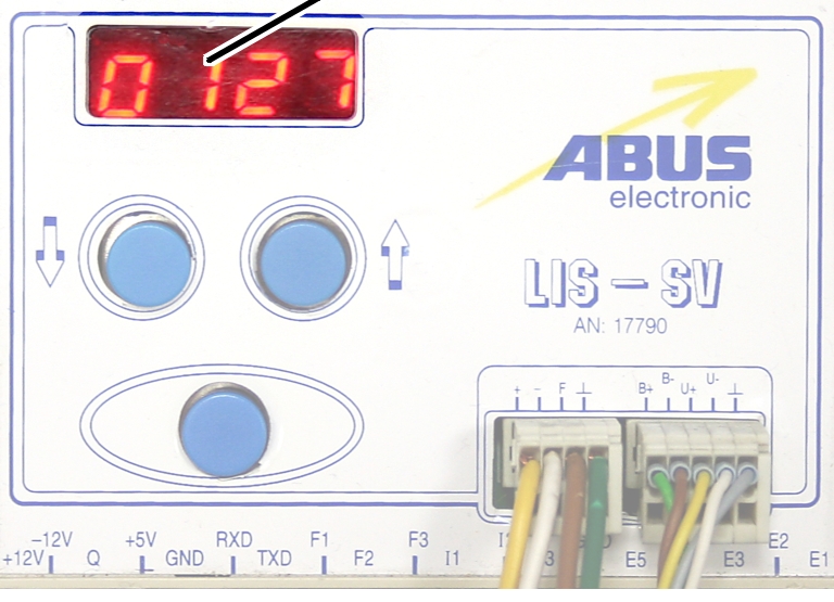
|
Display
of impulses |
|
|
|
● The counted
impulses of the encoder are shown in the LIS-SV display.