Move the load hook under the
upper limit switch range.
Move the load hook under the
upper limit switch range.
If the wire rope is damaged or has more broken wires than permitted (see Inspecting the wire rope), it must be replaced.
If the cable guide is damaged (see Inspecting the cable guide), it must be replaced.
The wire rope is a special lifting rope with a very high breaking strength. This ensures that it has a longer service life than a normal wire rope. This is why only genuine wire ropes from ABUS may be used.
These safety instructions apply specifically to changing the wire rope:
─ Cordon off a generous space for the work area under the wire rope hoist.
─ Ensure that the floor is swept clean.
This reduces soiling of the new wire rope.
─ If no unrolling device is available to unroll the wire rope, sufficient free space for this is required.
─ Position a scrap container or similar receptacle in the immediate vicinity of the lift platform and bottom block for the old wire rope.
─ For a wire rope diameter larger than 11 mm, the rope change should be performed with the assistance of a second person.
Move the load hook under the
upper limit switch range.
Measure, and note the position of the load
hook.
This makes adjusting the hoist limit switch after replacing the wire rope in many cases unnecessary.
If ABUControl is installed for the wire rope hoist, refer to the product manual “ABUControl”, section “Exchanging the wire rope” to prepare for the rope change.
Further steps for the wire rope change are then described in this product manual.
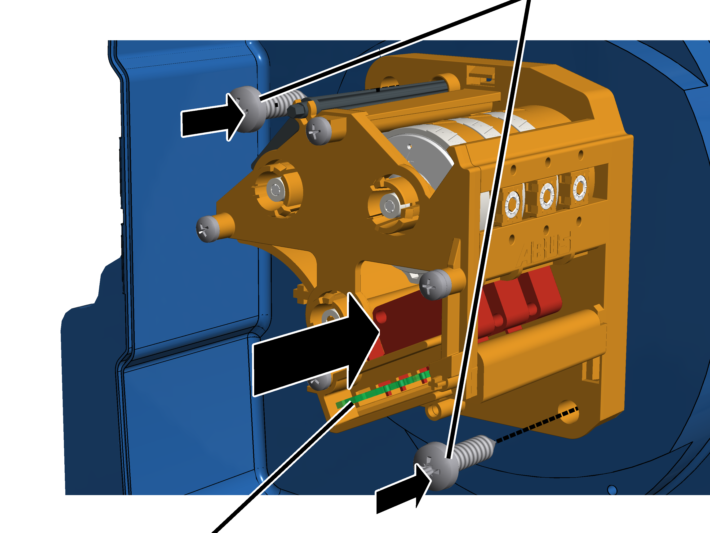
On the first cable drum:
|
|
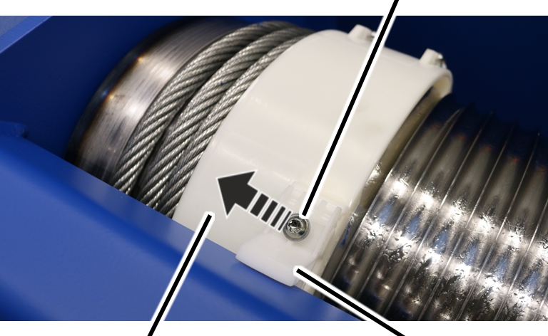
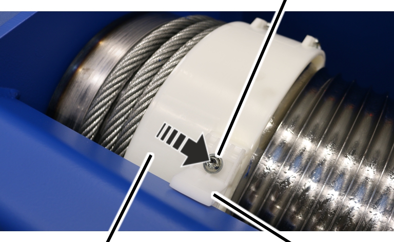
Self-tapping screw M6x16 |
|
| |
|
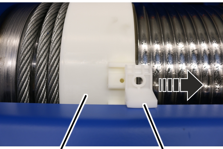
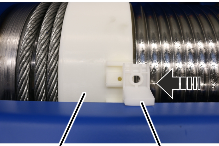
Rope guide ring |
Rope guide runner |
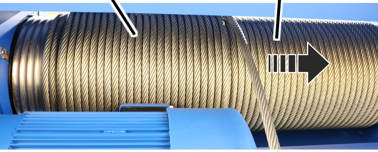
 Allow the wire rope to run off the
cable drum using the motor.
Allow the wire rope to run off the
cable drum using the motor.
Several wire rope windings should remain on the cable drum.
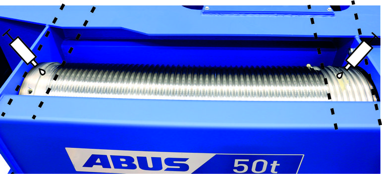
Unscrew the rope guide
runner.
|
| |
|
Rope guide ring |
Rope guide runner |
Push the rope guide runner away to one side
of the rope guide ring.
● The rope guide ring can now be turned freely on the cable drum.
On the first cable drum:
|
|
Clamping element |
|
| |
|
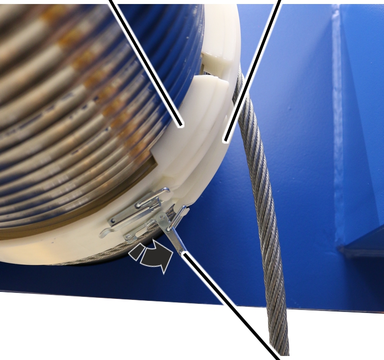
Rope guide ring |
Spring cotter |
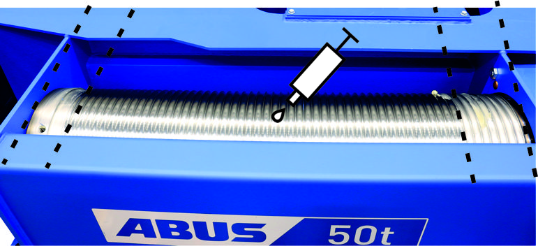
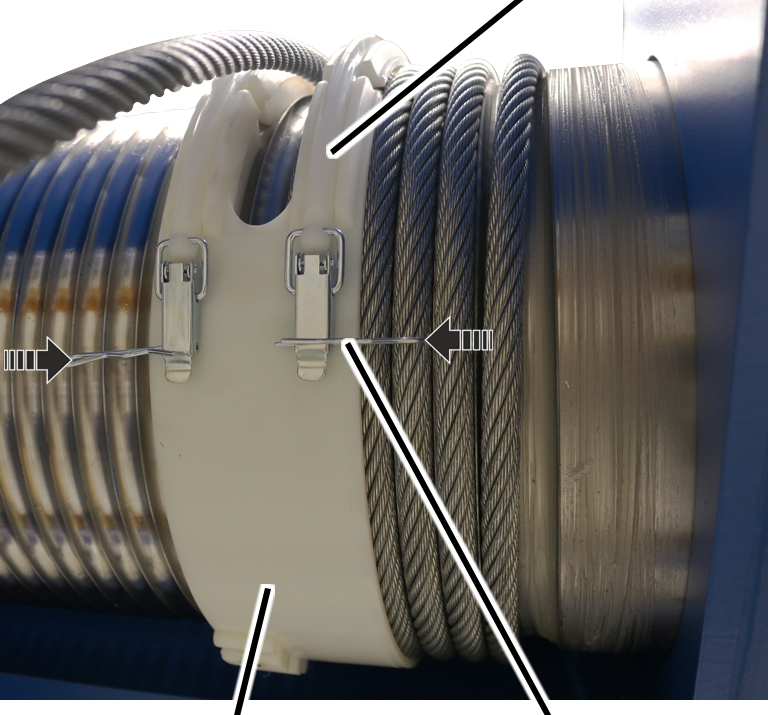
Pull the spring cotter out of the clamping
elements on the rope guide ring.
|
Rope guide ring |
Clamping element |
|
| |
|
|
Tension lever |
Open and release the tension lever of the
clamping element on the rope guide ring.
|
Cable drum |
Clamping element |
|
| |
|
Wire rope |
Rope guide ring |
Pull the rope guide ring with clamping elements from
the cable drum.
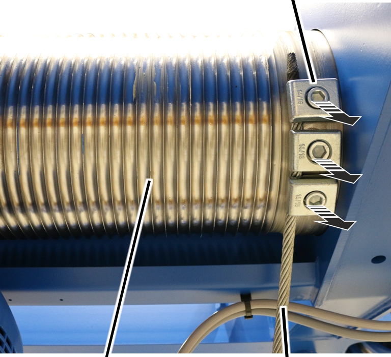
On the first cable drum:
|
|
End clamp |
|
| |
|
Cable drum |
Wire rope |
Allow the wire rope to run off the cable drum
using the motor.
Release the end clamps.
Completely remove the wire rope
from the cable drum.
Secure the wire rope against
falling and carefully set it down on the floor of the building.
|
|
Danger to persons from the wire rope falling. When loosening the wire rope, there is a risk that the wire rope may fall and cause serious injuries to persons or severe material damage. Secure the wire rope against falling. |
On the first cable drum:
Clean the cable drum.
|
|
Lubricate the cable drum from the start to
about the 8th or 10th turn.
Lubricate the cable drum behind
the last turn.
Lubricant: “Molykote PG-75”. For details, see Lubricants.
|
|
Lubricate the cable drum behind the
8th/10th turn up to the last turn.
Lubricant: “Chainlife S”. See Lubricants.
On the second cable drum:
Pull the wire rope back up using
the motor until the rope end is positioned 2 m below the first deflection
roller of the bottom block.
Pull the connection sleeve over
the ends of the old and new wire ropes.
Fix the connection sleeve in
place with duct tape.
The duct tape must be applied as smoothly as possible to ensure that there are no edges sticking up so the wire rope can be pulled up evenly.
Pull the wire rope up until the
new rope end is pulled through all of the deflection rollers and reaches the
cable drum.
Keep the wire rope taut and pull it up without twisting it.
|
|
Roll the wire rope out without twisting it. The wire rope will bend and become damaged if it is rolled out incorrectly. Do not pull the wire rope upwards away from a horizontally lying ring. Unroll the ring so it is vertically upright instead, and allow the wire rope to run onto the cable drum in the same direction as it was rolled onto the ring. |
Note
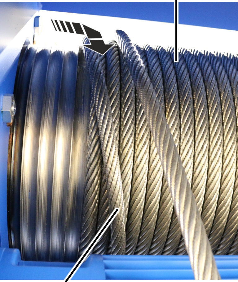
If the cable drum is completely full, the wire rope must be wound in the opposite direction on the cable drum as a second layer.
If there is not enough room on the cable drum:
|
|
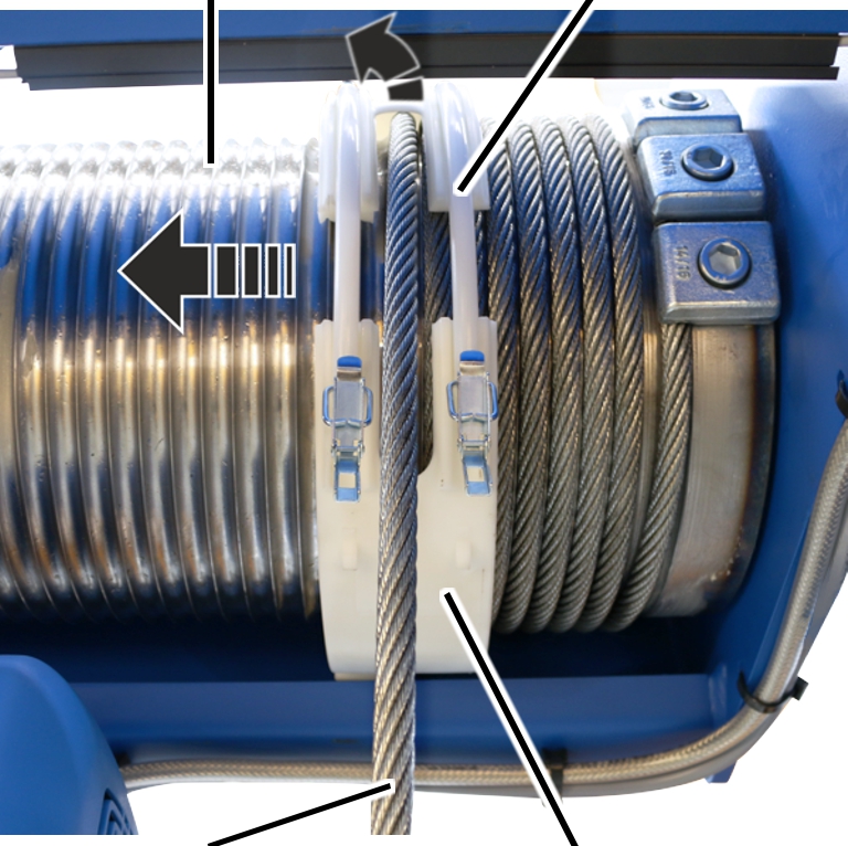
First layer |
|
| |
|
Cross the wire rope over for the second layer |
|
Cross the wire rope over and
wind the second layer at a slow lifting speed.
|
Second layer |
First layer |
|
| |
Continue winding the second
layer until the new rope end reaches the second cable drum.
On the second cable drum:
|
|
End clamp |
|
| |
|
Cable drum |
Wire rope |
Secure the new rope end.
Remove the connection
sleeve.
Allow the wire rope to run off
the cable drum using the motor.
Release the end clamps.
Completely remove the wire rope
from the cable drum.
Secure the wire rope against
falling and carefully set it down.
Ideally, a container should be positioned under the wire rope hoist so that the wire rope can be unwound directly into it.
|
|
Danger to persons due to falling wire rope. When loosening the wire rope, there is a risk that the wire rope may fall and cause serious injuries to persons or severe material damage. Secure the wire rope against falling. |
On the second cable drum:
Clean the cable drum.
|
|
Lubricate the cable drum from
the start to about the 8th or 10th turn.
Lubricate the cable drum behind
the last turn.
Lubricant: “Molykote PG-75”. For details, see Lubricants.
|
|
Lubricate the cable drum behind
the 8th/10th turn up to the last turn.
Lubricant: “Chainlife S”. See Lubricants.
Note
|
|
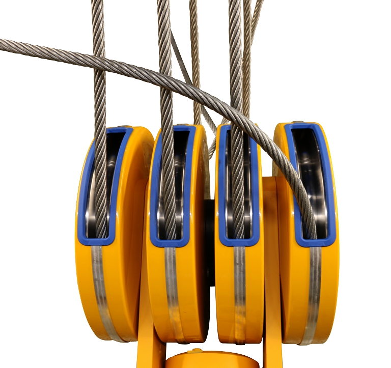
The wire rope must be guided into the second cable drum in front of the rope threads in the bottom block to ensure that the wire rope does not become twisted or guided to the second cable drum between the threads of the wire rope.
|
|
Roll the wire rope out without twisting it. The wire rope will bend and become damaged if it is rolled out incorrectly. Do not pull the wire rope upwards away from a horizontally lying ring. Unroll the ring so it is vertically upright instead, and allow the wire rope to run onto the cable drum in the same direction as it was rolled onto the ring. |
On the second cable drum:
|
Cable drum |
Fillister-head screw M8x20 |
|
| |
|
Wire rope |
End clamp |
Roll out the wire rope without twisting
it.
Thoroughly clean the
fillister-head screws of the end clamps.
The fillister-head screws were previously bolted with a thread lock coating or a thread lock. The residues must be completely removed before the fillister-head screw may be used again.
The thread lock coating and thread lock are single-use only.
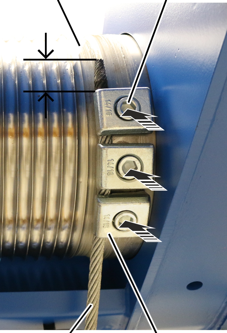
Push the wire rope under the end
clamps far enough that the rope protrusion is about 30 mm.
Tighten the end clamps with
fillister-head screws and secure with (medium strength) thread lock.
|
Size |
Number |
rope diameter |
Tightening torque |
|
GM 5000 |
3 |
14 mm |
210 Nm |
|
GM 6000 |
3 |
16.2 mm |
210 Nm |
|
GM 7000 |
3 |
14 mm |
210 Nm |
|
GM 7000 |
3 |
20.2 mm |
425 Nm |
No pre-assembly is necessary on a cable guide for a GM 800 to GM 3000. This section can be skipped over in this case.
On the cable guide for a wire rope hoist with hoist drive GM 5000 or GM 6000, the clamping elements are hooked into catches on the rope guide ring. The eyebolts for clamping the rope guide ring are located above on the clamping elements.
|
Eyebolt |
Rope guide ring |
|
| |
|
Clamping element |
Catches |
Insert the clamping elements (2x) with the eyebolts
in the first catch on the rope guide ring.
Grease the groove of the rope
guide ring from the inside.
Lubricant: “Molykote PG-75”. For details, see Lubricants.
|
Clamping elements |
Bolt |
|
| |
|
Rope guide ring |
|
Push the bolt through the
clamping elements and the rope guide ring.
|
SL safety clip |
Bolt |
|
| |
|
Rope guide ring |
Clamping element |
Push the SL safety clip onto the
bolt.
Grease the groove of the rope
guide ring from the inside.
Lubricant: “Molykote PG-75”. For details, see Lubricants.
On the second cable drum:
|
Cable drum |
Clamping element |
|
| |
|
Wire rope |
Rope guide ring |
Pull the rope guide ring with
clamping elements onto the cable drum.
Position the wire rope between
the clamping elements.
Check that both ends of the rope
guide ring lie in the same groove of the cable drum.
The ends of the rope guide ring must be aligned.
|
Rope guide ring |
Clamping element |
|
| |
|
|
Tension lever |
Insert the tension lever on the
clamping elements into the rope guide ring and close it.
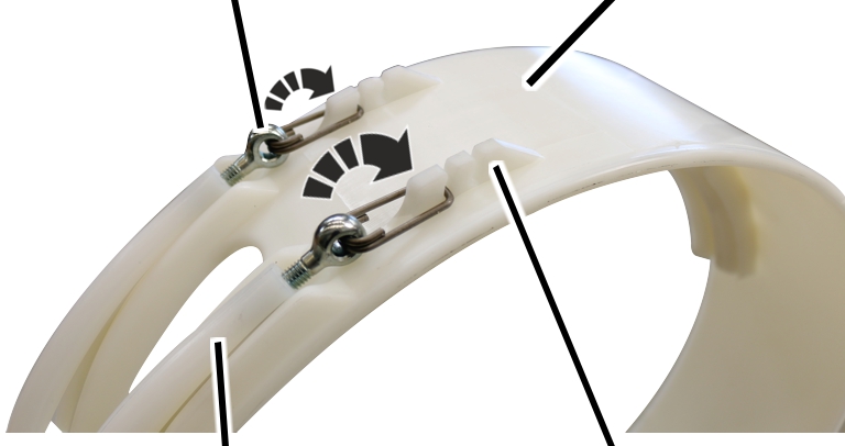
Open the tension lever again and
adjust the rope guide ring with the eyebolts so that the rope guide ring rests
securely on the wire rope but can still be rotated.
|
|
Clamping element |
|
| |
|
Rope guide ring |
Spring cotter |
Push the spring cotter into the
tension lever of the clamping elements.
On the second cable drum:
|
| |
|
Rope guide ring |
Rope guide runner |
Put the rope guide runner on the drum housing
and push it laterally into the rope guide ring.
|
|
Screw |
|
| |
|
Rope guide ring |
Rope guide runner |
Screw on the rope guide runner with the
self-tapping screw M6x16. 5 Nm.
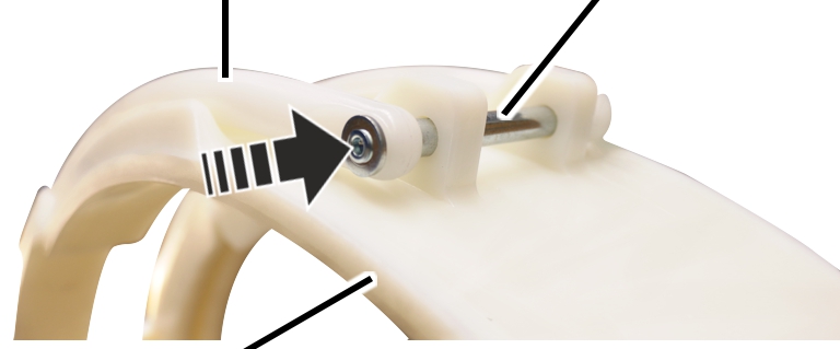
On the first cable drum:
|
Cable drum |
Fillister-head screw M8x20 |
|
| |
|
Wire rope |
End clamp |
 Roll out the wire rope without
twisting it.
Roll out the wire rope without
twisting it.
Thoroughly clean the
fillister-head screws of the end clamps.
The fillister-head screws were previously bolted with a thread lock coating or a thread lock. The residues must be completely removed before the fillister-head screw may be used again.
The thread lock coating and thread lock are single-use only.
Push the wire rope under the end
clamps far enough that the rope protrusion is about 30 mm.
Tighten the end clamps with
fillister-head screws and secure with (medium strength) thread lock.
|
Size |
Number |
rope diameter |
Tightening torque |
|
GM 5000 |
3 |
14 mm |
210 Nm |
|
GM 6000 |
3 |
16.2 mm |
210 Nm |
|
GM 7000 |
3 |
14 mm |
210 Nm |
|
GM 7000 |
3 |
20.2 mm |
425 Nm |
Pull the wire rope taut and use
the motor to wind it onto the cable drum by 6 to 8 turns, ensuring it is taut
and not twisted.
On a cable guide for a GM 5000 to GM 7000, the clamping elements must be secured on the rope guide ring.
No pre-assembly is necessary on a cable guide for a GM 800 to GM 3000. This section can be skipped over in this case.
On the cable guide for a wire rope hoist with hoist drive GM 5000 or GM 6000, the clamping elements are hooked into catches on the rope guide ring. The eyebolts for clamping the rope guide ring are located above on the clamping elements.
|
Eyebolt |
Rope guide ring |
|
| |
|
Clamping element |
Catches |
Insert the clamping elements
(2x) with the eyebolts in the first catch on the rope guide ring.
Grease the groove of the rope
guide ring from the inside.
Lubricant: “Molykote PG-75”. For details, see Lubricants.
On the cable guide for a wire rope hoist with hoist drive GM 7000, the clamping elements are secured on the rope guide ring using a bolt and an SL safety clip. The eyebolts for tensioning the rope guide ring are located below on the clamping elements.
|
Clamping elements |
Bolt |
|
| |
|
Rope guide ring |
|
Push the bolt through the
clamping elements and the rope guide ring.
|
SL safety clip |
Bolt |
|
| |
|
Rope guide ring |
Clamping element |
Push the SL safety clip onto the
bolt.
Grease the groove of the rope
guide ring from the inside.
Lubricant: “Molykote PG-75”. For details, see Lubricants.
Note
Before the second cable guide is mounted, there must be the same number of turns on both cable drums, in other words, 5 to 6 turns in front of the cable guide.
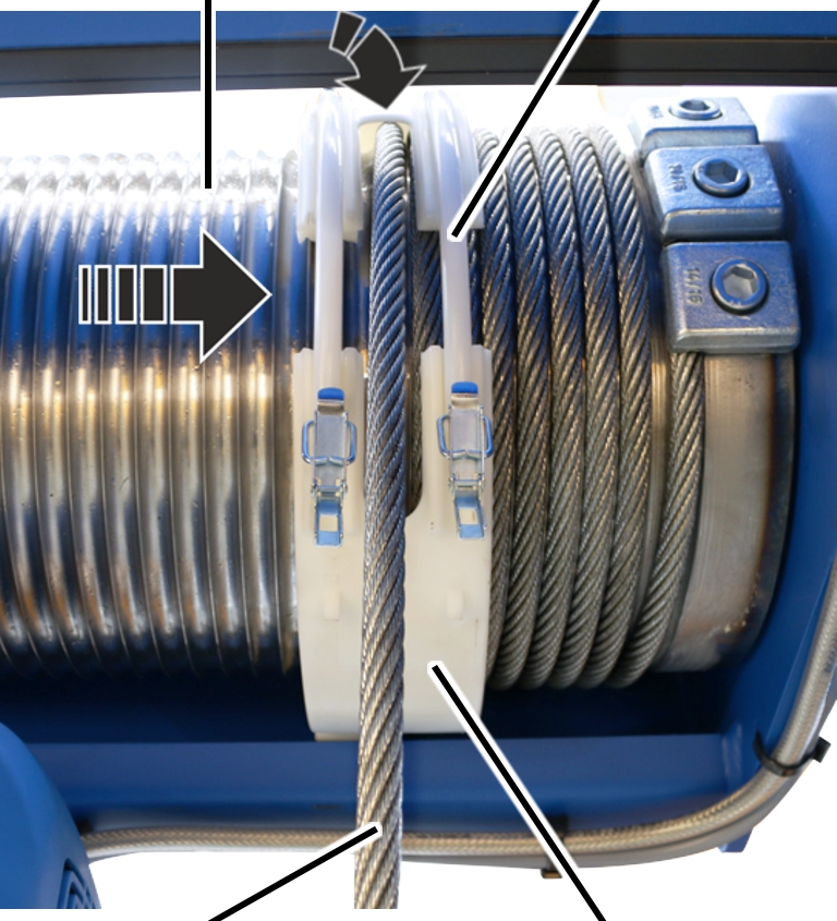
On the first cable drum:
|
Cable drum |
Clamping element |
|
| |
|
Wire rope |
Rope guide ring |
 Pull the rope guide ring with
clamping elements onto the cable drum.
Pull the rope guide ring with
clamping elements onto the cable drum.
Position the wire rope between
the clamping elements.
Check that both ends of the rope
guide ring lie in the same groove of the cable drum.
The ends of the rope guide ring must be aligned.
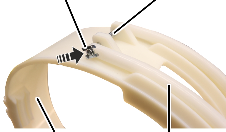
|
Rope guide ring |
Clamping element |
|
| |
|
|
Tension lever |
Insert the tension lever on the
clamping elements into the rope guide ring and close it.
If necessary:
Open the tension lever again and
adjust the rope guide ring with the eyebolts so that the rope guide ring rests
securely on the wire rope but can still be rotated.
|
|
Clamping element |
|
| |
|
Rope guide ring |
Spring cotter |
Push the spring cotter into the
tension lever of the clamping elements.
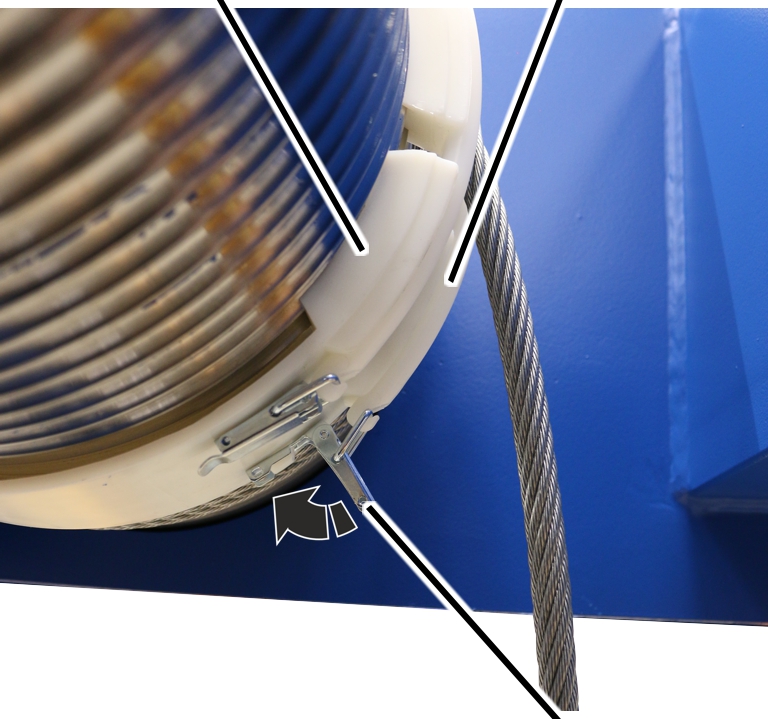
On the first cable drum:
|
| |
|
Rope guide ring |
Rope guide runner |
Put the rope guide runner on the
drum housing and push it laterally into the rope guide ring.
|
|
Screw |
|
| |
|
Rope guide ring |
Rope guide runner |
Screw on the rope guide runner
with the self-tapping screw M6x16. 5 Nm.
Use the motor to wind up the
wire rope completely.
If ABUControl is installed for the wire rope hoist, refer to the “Exchanging the wire rope” section of the “ABUControl” product manual to complete the rope change.
Further steps are then described in this product manual.
Move the load hooks to the
position you noted previously.
|
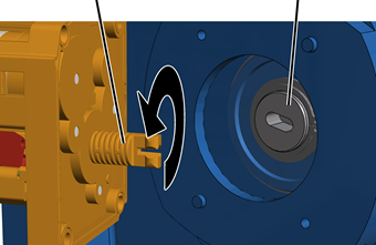
Shaft |
Bearing flange |
|
| |
Open the housing cover of the
hoist limit switch enclosure on the cable drum.
Rotate the shaft of the gear
limit switch so that it matches the elongated hole in the bearing flange of the
cable drum.
|
Plastic screws B6, 3x25 | |
|
| |
|
Cam switch PCB |
|
Insert the gear limit switch
with the shaft in the elongated hole on the bearing flange and guide it onto the
two pins.
Screw the gear limit switch
tight with the plastic screws B6, 3x25. 3 Nm.
Plug
in the connector of the connection cable on the cam switch PCB.
If the switching points have moved:
Normally, the adjustment of the hoist limit switch after replacing the wire rope can in many cases be omitted, since the position of the load hook was previously measured and then travelled to again. In special cases (e.g. if the wire rope is severely damaged or has been incorrectly rolled onto the cable drum), the switching points may need to be readjusted.
Reset switching points for the
bottom hoist limiter, the top hoist limiter and the backup limiter.
With ABUS electrics 3 with contactor control: see product manual “ABUS gear limit switch”.
With ABUS electrics 3 with ABULiner: see product manual “Frequency converter control of the lifting speed for ABUS electrics 3”.