Air gap (between magnet body and anchor plate)
Brake lining thickness
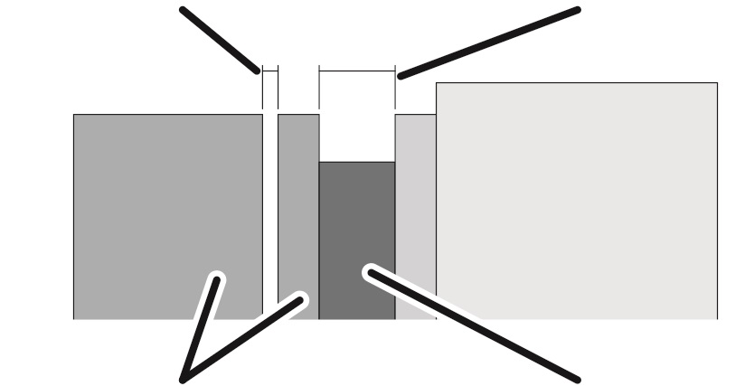
Magnet body and anchor plate
Brake rotor with brake lining
If the air gap is wider than permitted, it must be readjusted.
Overview:
|
Air gap (between magnet body and anchor plate) |
Brake lining thickness |
|
| |
|
Magnet body and anchor plate |
Brake rotor with brake lining |
|
Dimension |
Size |
Size |
|
Maximum air gap |
1.3 mm |
1.3 mm |
|
Minimum air gap |
0.3 mm |
0.3 mm |
|
Brake lining thickness, new |
7.5 mm |
8.5 mm |
|
Brake lining thickness, minimum |
4.5 mm |
5.5 mm |
Due to the wear of the brake lining as the motor is braked, the brake rotor gradually becomes thinner. The anchor plate is thereby pressed ever further toward the brake rotor during braking and the air gap thus becomes wider. If the air gap has reached its maximum width, a gap limiter prevents the anchor plate from being pressed any further, thus ensuring that the anchor plate is reliably ventilated. When the gap limiter is employed, the braking effectiveness gradually lessens.
|
Magnet body |
Brake rotor with brake lining |
|
| |
|
Anchor plate |
|
If the brake lining is worn, the air gap will be larger. See Inspecting the brake on the drive with the helical gear unit. If the air gap is larger than maximally permitted, the brake must be readjusted. If the brake rotor is too thin due to wear, it must be replaced. See Inspecting the brake on the drive with the helical gear unit.
|
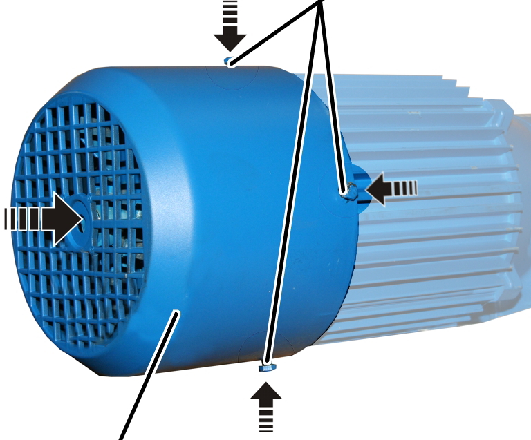
Screws | |
|
| |
|
Fan cover |
|
 Unscrew and remove screws
(4x).
Unscrew and remove screws
(4x).
Take off the fan cover.
|
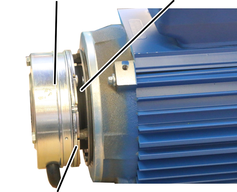
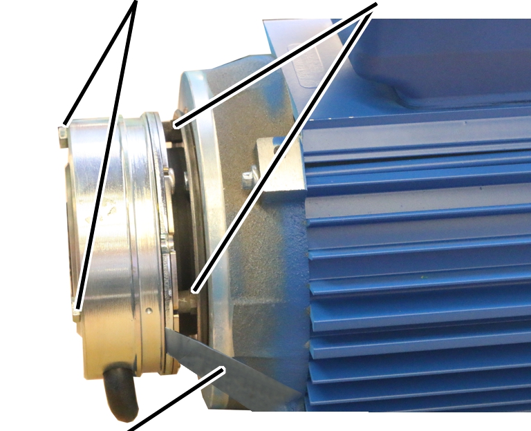
Hexagon head screws |
Banjo bolts |
|
| |
|
Feeler gauge |
|
Unscrew the hexagon head screws
(3x) by a half turn.
Screw in the banjo bolts (3x) by
a half turn in the direction of the magnet body.
Read off the minimum width of
the air gap from the table.
|
Dimension |
Size 80 / 112 |
Size 140 |
|
Maximum air gap |
1.3 mm |
1.3 mm |
|
Minimum air gap |
0.3 mm |
0.3 mm |
Insert the appropriate feeler
gauge directly next to one of the hexagon head screws in the air gap between
magnet body and anchor plate.
Tighten the hexagon head screws
so that the feeler gauge can still be pulled from the air gap.
● The air gap on this hexagon head screw is now adjusted to the minimum width.
Repeat the steps for all hexagon
head screws (3x).
Screw the banjo bolts (3x) in
the direction of the motor until hand-tight.
Tighten the hexagon head screws
(3x).
|
Size |
Size and length |
Tightening torque |
|
Size 80 / 112 |
M4x45 |
3 Nm |
|
Size 140 |
M5x55 |
6 Nm |
● The brake is fixed with screws.
Check the air gap next to all
three hexagon head screws. If different than the minimum width, repeat the
adjustment.
|
|
Screws | |
|
| ||
|
Fan cover |
| |
Attach fan cover.
Tighten screws (4x).