Air gap (between magnet body and anchor plate)
Brake lining thickness
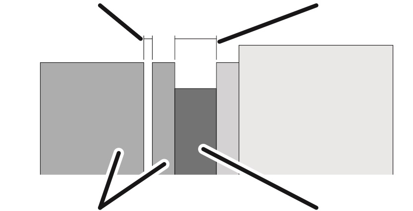
Magnet body and anchor plate
Brake rotor with brake lining
If the air gap is wider than permitted, it must be readjusted.
Overview:
|
Air gap (between magnet body and anchor plate) |
Brake lining thickness |
|
| |
|
Magnet body and anchor plate |
Brake rotor with brake lining |
|
Dimension |
Value |
|
Air gap between anchor plate and magnet body |
Between 0.4 mm and 1.1 mm |
|
Target value for air gap |
0.4 mm |
|
Size |
Brake lining thickness (minimum) [mm] | ||
|
Hoist motor L6 |
Hoist motor H6 |
Hoist motor U6 | |
|
800.4 |
9.3 |
9.3 |
9.3 |
|
1000.7 |
9.3 |
9.3 |
11.3 |
|
2000.3 |
9.3 |
11.3 |
- |
|
3000.4 |
11.3 |
12.3 |
- |
|
5000.3 |
12.3 |
13.8 |
- |
|
6000.3 |
13.8 |
- |
- |
|
7000.1 |
- |
13.8 |
13.8 |
As soon as the hoist motor stops running, the anchor plate presses against the brake rotor through spring force, braking the hoist motor. An air gap is created between the magnet body and the anchor plate. When the hoist motor starts up, the magnet body pulls the anchor plate away from the brake rotor and the hoist motor can rotate freely again.
If the brake lining is worn, the air gap will be larger. See Inspecting the brake on the hoist drive. If the air gap is larger than the maximum permitted, the brake must be readjusted. If the brake lining on the brake rotor is worn too thin, it must be replaced. See Replacing the brake rotor on the hoist drive.
|
| |
|
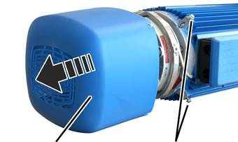
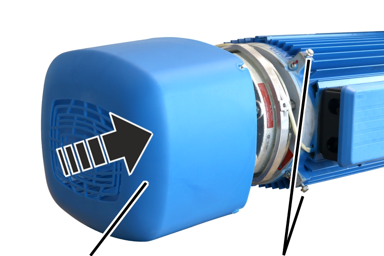
Fan cover |
Rib screws |
 Unscrew the rib screws
(3x) of the fan cover.
Unscrew the rib screws
(3x) of the fan cover.
Take off the fan
cover.
|
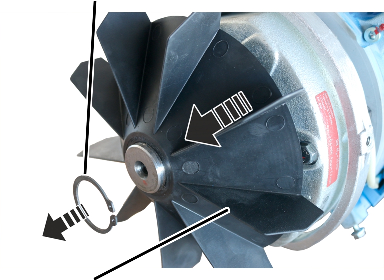
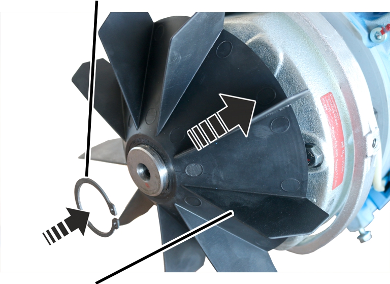
Circlip |
| |
|
| ||
|
Fan blade |
| |
Remove the circlip.
Remove the fan blade.
|
|
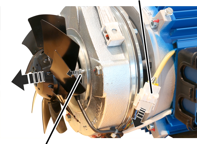
Do not allow the auxiliary fan to hang from the connection cable! If the auxiliary fan hangs from the connection cable, it could break. If present, unplug the plug-in connection so that the auxiliary fan can be laid aside during the assembly. If no plug-in connection is present, leave the auxiliary fan connected and secure it after removal (e.g. with a lashing strap). |
|
|
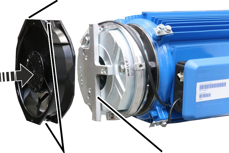
Plug-in connection |
|
| |
|
Hexagon head screw |
|
If present: Unplug the
plug-in connection from the auxiliary fan.
Release the hexagon head
screws (3x) on the auxiliary fan and remove the auxiliary fan.
If the auxiliary fan does
not have a plug-in connection: Leave the auxiliary fan connected and secure it
on the hoist motor, e.g. with a lashing strap.
|
|
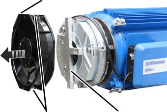
Do not allow the auxiliary fan to hang from the connection cable! If the auxiliary fan hangs from the connection cable, it could break. Unplug the plug-in connection so that the auxiliary fan can be laid aside during the assembly. |
|
Plug-in connection |
|
|
| |
|
Fillister-head screw |
Mount |
Unplug the plug-in
connection from the auxiliary fan.
Release the fillister-head
screws (2x) on the auxiliary fan and remove the auxiliary fan.
|
| |
|
O-ring |
|
Remove the O-ring.
Clean the entire brake
with compressed air.
|
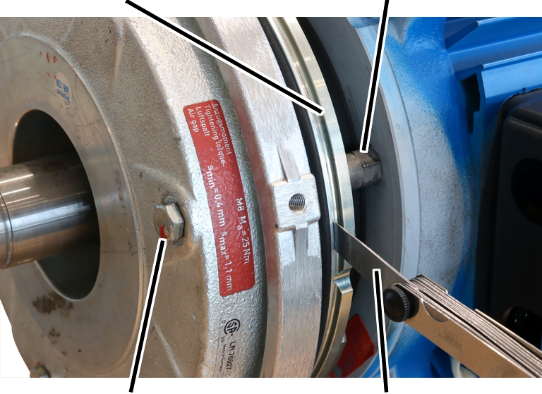
Magnet body |
Banjo bolt |
|
| |
|
Hexagon head screw |
Feeler gauge |
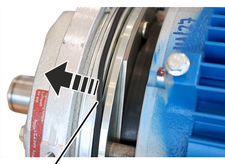
Unscrew the hexagon head screws (3x) by a half
turn.
Screw in the banjo bolts
(3x) by a half turn in the direction of the magnet body.
Read off the nominal width
of the air gap from the table.
|
Dimension |
Value |
|
Air gap between anchor plate and magnet body |
Between 0.4 mm and 1.1 mm |
|
Target value for air gap |
0.4 mm |
|
Size |
Brake lining thickness (minimum) [mm] | ||
|
Hoist motor L6 |
Hoist motor H6 |
Hoist motor U6 | |
|
800.4 |
9.3 |
9.3 |
9.3 |
|
1000.7 |
9.3 |
9.3 |
11.3 |
|
2000.3 |
9.3 |
11.3 |
- |
|
3000.4 |
11.3 |
12.3 |
- |
|
5000.3 |
12.3 |
13.8 |
- |
|
6000.3 |
13.8 |
- |
- |
|
7000.1 |
- |
13.8 |
13.8 |
Tighten the hexagon head
screws so that the feeler gauge can still be pulled from the air gap.
● The air gap on this hexagon head screw is now adjusted to the set width.
Repeat the steps for all
hexagon head screws (3x).
|
|
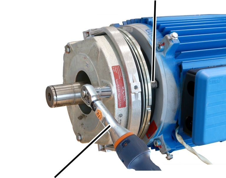
Banjo bolt |
|
| |
|
Torque wrench |
|
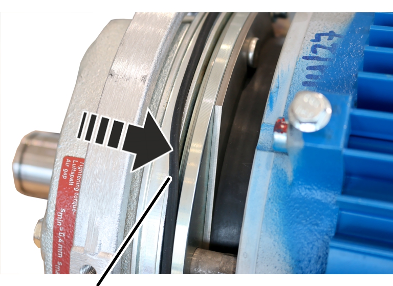
Screw the banjo bolts (3x) in the direction of the
hoist motor until hand-tight.
Screw on the hexagon head
screws (3x).
|
Hexagon head screw |
Tightening torque |
|
M6x70 |
10 Nm |
|
M8x80 |
25 Nm |
|
M8x90 |
25 Nm |
|
M8x100 |
25 Nm |
● The brake is fixed with screws.
Check the air gap next to
all three hexagon head screws. If different than the set width, repeat the
adjustment.
|
| |
|
O-ring |
|
Insert the O-ring.
|
Circlip |
| |
|
| ||
|
Fan blade |
| |
 Insert the fan blade on
the motor shaft.
Insert the fan blade on
the motor shaft.
Insert the circlip.
|
|
Plug-in connection |
|
| |
|
Hexagon head screw M5x10 |
|
Place the auxiliary fan on
the magnet body.
Bolt on the auxiliary fan
with hexagon head screws M5x10 (3x).4,8 Nm. Secure with thread-locking
compound (medium tightness).
If necessary: Insert the
plug-in connection from the auxiliary fan.
|
Plug-in connection |
|
|
| |
|
Fillister-head screw M4x16 |
Mount |
Place the auxiliary fan on
the mount.
Screw the auxiliary fan
onto the mounting using fillister-head screws M4x12 (2x). 2,4 Nm. Secure
with thread-locking compound (medium tightness).
Insert the plug-in
connection from the auxiliary fan.
|
| |
|
Fan cover |
Rib screws |
Attach fan cover.
Screw in the rib screws
(3x) of the fan cover.