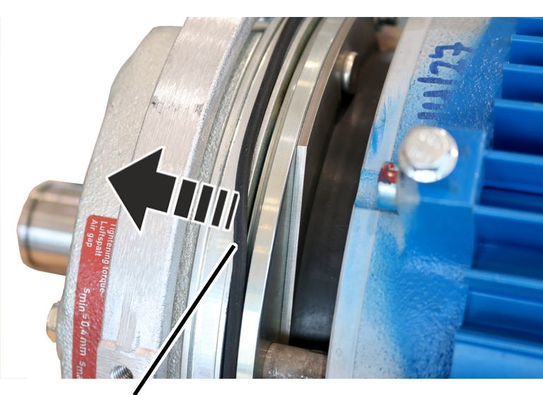
Air gap (between magnet body and anchor plate)
Brake lining thickness
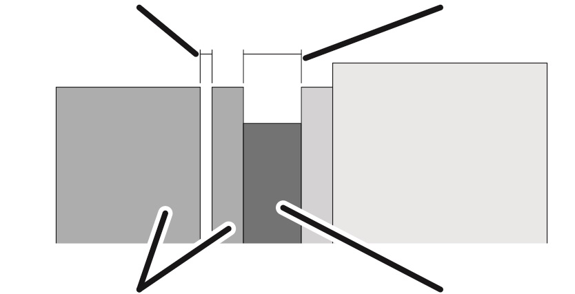
Magnet body and anchor plate
Brake rotor with brake lining
|
Air gap (between magnet body and anchor plate) |
Brake lining thickness |
|
| |
|
Magnet body and anchor plate |
Brake rotor with brake lining |
|
Dimension |
Value |
|
Air gap between anchor plate and magnet body |
Between 0.4 mm and 1.1 mm |
|
Target value for air gap |
0.4 mm |
|
Brake lining thickness (minimum) [mm] | |||
|
Hoist motor L6 |
Hoist motor H6 |
Hoist motor U6 | |
|
800.4 |
9.3 |
9.3 |
9.3 |
|
1000.7 |
9.3 |
9.3 |
11.3 |
|
2000.3 |
9.3 |
11.3 |
- |
|
3000.4 |
11.3 |
12.3 |
- |
|
5000.3 |
12.3 |
13.8 |
- |
|
6000.3 |
13.8 |
- |
- |
|
7000.1 |
- |
13.8 |
13.8 |
This is the point at which the air gap must be readjusted at the latest. If the minimum lining thickness has been reached, the brake rotor must be replaced.
|
| |
|
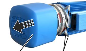
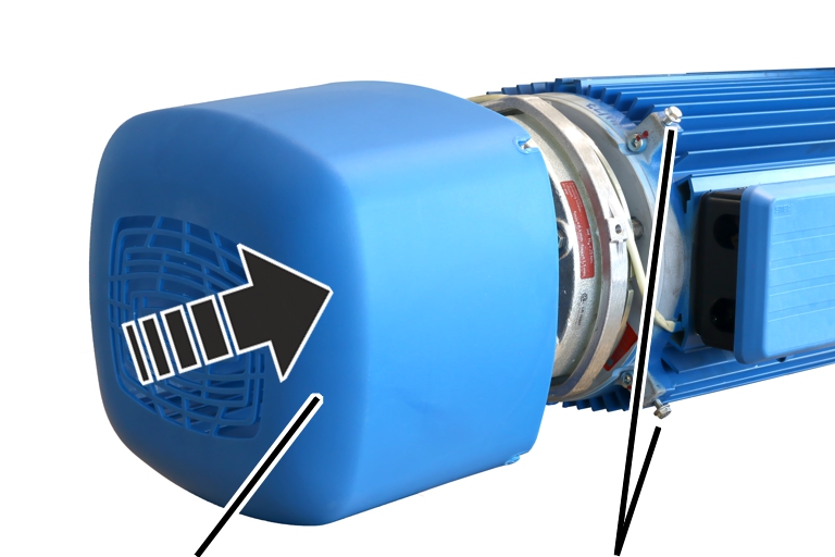
Fan cover |
Rib screws |
 Unscrew the rib screws
(3x) of the fan cover.
Unscrew the rib screws
(3x) of the fan cover.
Take off the fan
cover.
|
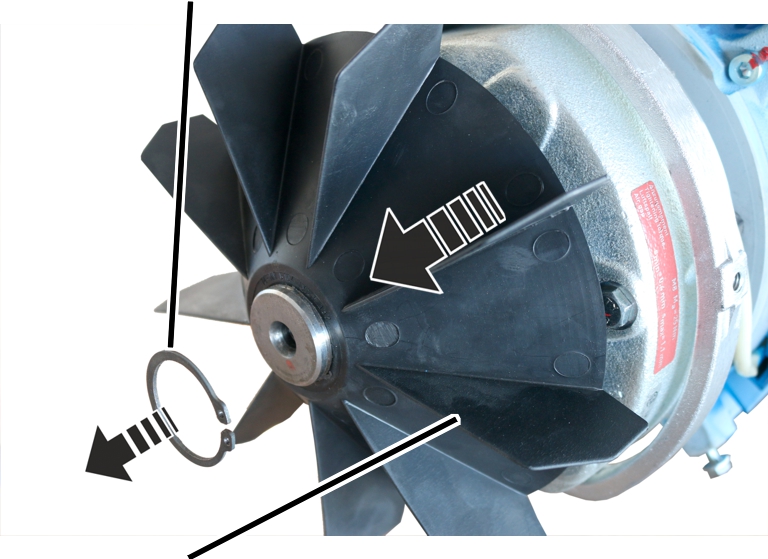
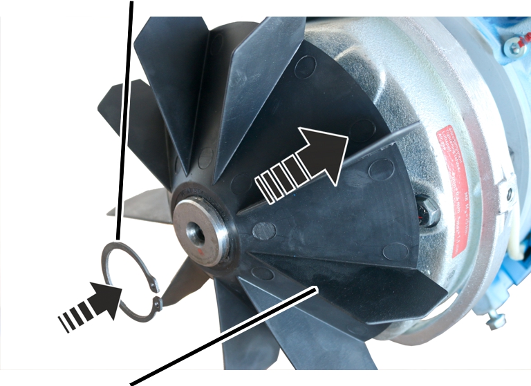
Circlip |
| |
|
| ||
|
Fan blade |
| |
 Remove the circlip.
Remove the fan blade.
|
|
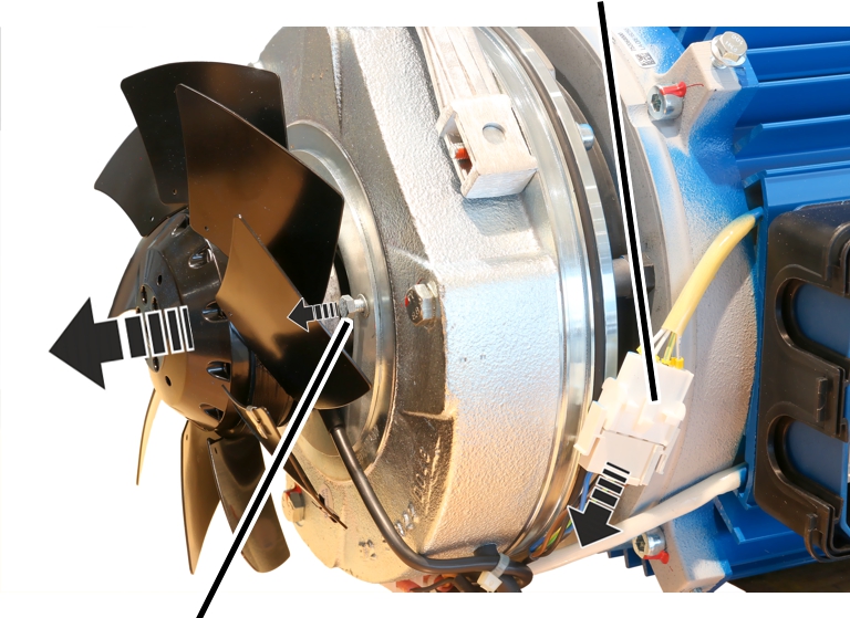
Do not allow the auxiliary fan to hang from the connection cable! If the auxiliary fan hangs from the connection cable, it could break. If present, unplug the plug-in connection so that the auxiliary fan can be laid aside during the assembly. If no plug-in connection is present, leave the auxiliary fan connected and secure it after removal (e.g. with a lashing strap). |
|
|
Plug-in connection |
|
| |
|
Hexagon head screw |
|
If present: Unplug the
plug-in connection from the auxiliary fan.
Release the hexagon head
screws (3x) on the auxiliary fan and remove the auxiliary fan.
If the auxiliary fan does
not have a plug-in connection: Leave the auxiliary fan connected and secure it
on the hoist motor, e.g. with a lashing strap.
|
|
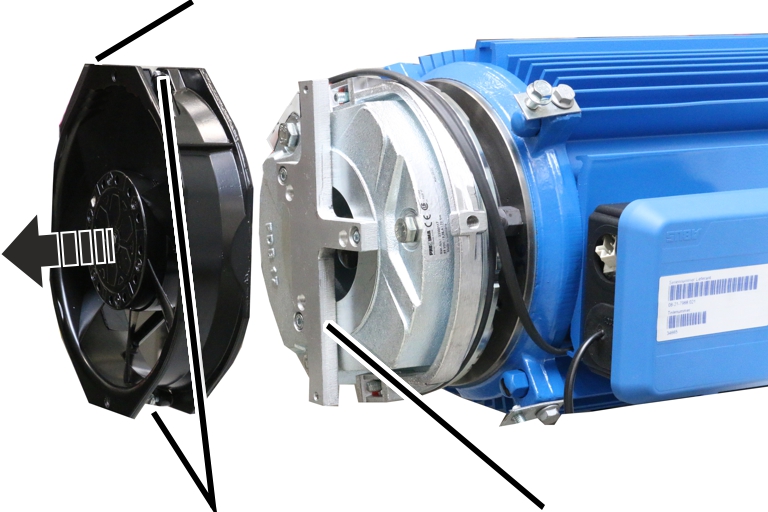
Do not allow the auxiliary fan to hang from the connection cable! If the auxiliary fan hangs from the connection cable, it could break. Unplug the plug-in connection so that the auxiliary fan can be laid aside during the assembly. |
|
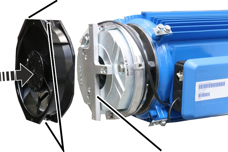
Plug-in connection |
|
|
| |
|
Fillister-head screw |
Mount |
Unplug the plug-in
connection from the auxiliary fan.
Release the fillister-head
screws (2x) on the auxiliary fan and remove the auxiliary fan.
|
| |
|
O-ring |
|
Remove the O-ring.
Clean the entire brake
with compressed air.
|
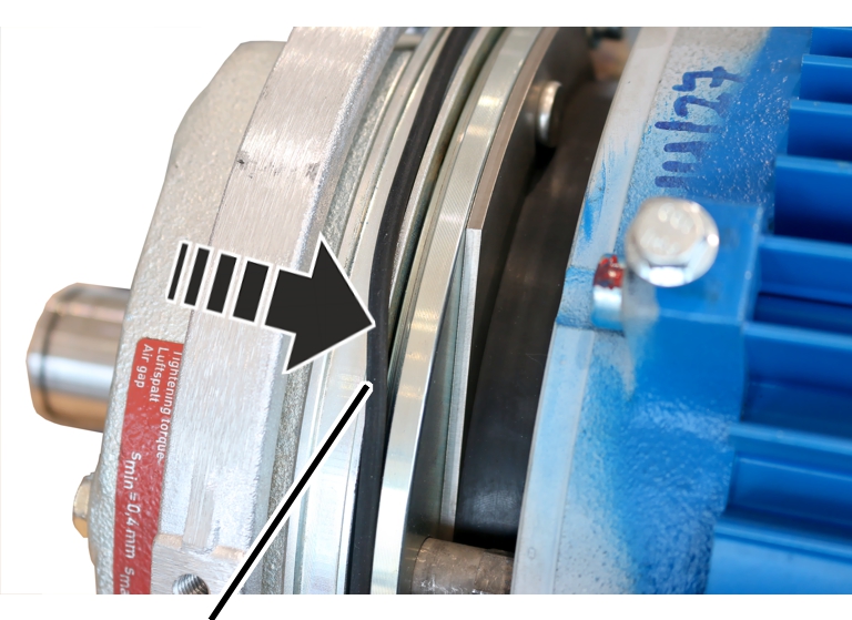
Magnet body |
Anchor plate |
|
| |
|
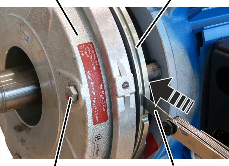
Hexagon head screw |
Feeler gauge |
If the air gap has reached
the maximum width of the operating range (1.1 mm), adjust the brake. See Setting the air gap on
the brake.
If the width of the air gap is within the permitted range but usage behaviour leads to the expectation that the air gap will be wider than permitted before the next regular inspection, the air gap must be readjusted now.
Repeat the steps for all hexagon head screws
(3x).
|
|
Danger from falling bottom block! If the hoist drive, the hoist motor or the brake are removed, the cable drum of the wire rope hoist will no longer be supported. This can cause the wire rope to unwind in an uncontrolled manner and fall down with the bottom block. Secure the bottom block on the wire rope hoist! |
|
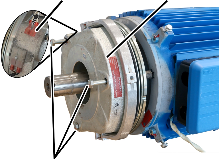
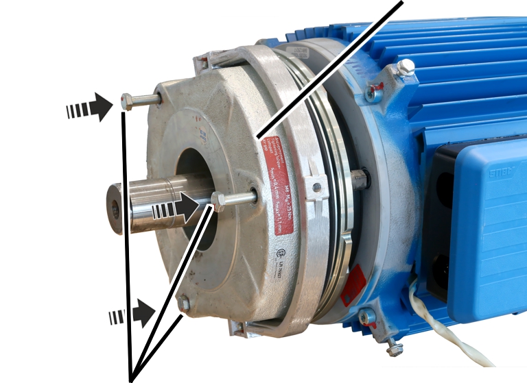
Power supply |
Magnet body |
|
| |
|
Hexagon head screws |
|
Disconnect the power supply of the magnet
body.
Release the hexagon head
screws (3x).
Pull the magnet body from
the motor shaft.
|
| |
|
| |
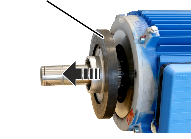
Pull the brake rotor from
the hub and from the motor shaft.
|
| |
|
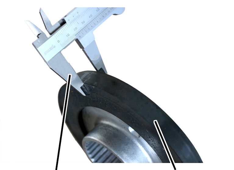
Calliper |
Brake rotor |
Check the thickness of the
brake lining with a calliper.
If the brake rotor is
thinner than specified in the table: replace the brake rotor. See Replacing the
brake rotor on the hoist drive.
|
Size |
Brake lining thickness (minimum) [mm] | ||
|
Hoist motor L6 |
Hoist motor H6 |
Hoist motor U6 | |
|
800.4 |
9.3 |
9.3 |
9.3 |
|
1000.7 |
9.3 |
9.3 |
11.3 |
|
2000.3 |
9.3 |
11.3 |
- |
|
3000.4 |
11.3 |
12.3 |
- |
|
5000.3 |
12.3 |
13.8 |
- |
|
6000.3 |
13.8 |
- |
- |
|
7000.1 |
- |
13.8 |
13.8 |
The area (air gap) between the magnet body and the anchor plate is protected from dust by an O-ring. The O-ring must not become damaged or lost.
Check the O-ring.
The O-ring may not be torn, dented or otherwise damaged, nor may it be missing completely.
If the O-ring is damaged
or missing, fit a new O-ring.
|
|
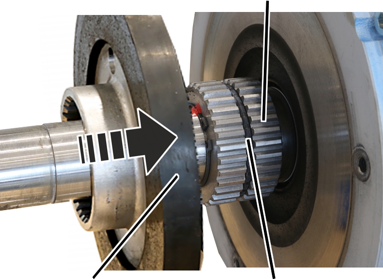
Hub |
|
| |
|
Brake rotor |
O-ring |
If present: Check whether
the O-ring lies fully in the groove of the hub.
Slide the brake rotor over
the motor shaft onto the hub.
|
|
Magnet body |
|
| |
|
Hexagon head screws |
|
Slide the magnet body onto
the motor shaft.
Screw on the hexagon head
screws (3x).
|
Tightening torque | |
|
M6x70 |
10 Nm |
|
M8x80 |
25 Nm |
|
M8x90 |
25 Nm |
|
M8x100 |
25 Nm |
If necessary, replace the hexagon head screws and banjo bolts with new ones.
Ideally, the magnet body should not only be screwed back on, but also the air gap should be readjusted to optimise the operating range of the brake. See Setting the air gap on the brake.
Connect the power supply
of the magnet body.
|
| |
|
O-ring |
|
Insert the O-ring.
|
Circlip |
| |
|
| ||
|
Fan blade |
| |
Insert the fan blade on
the motor shaft.
Insert the circlip.
|
|
Plug-in connection |
|
| |
|
Hexagon head screw M5x10 |
|
Place the auxiliary fan on
the magnet body.
Bolt on the auxiliary fan
with hexagon head screws M5x10 (3x).4,8 Nm. Secure with thread-locking
compound (medium tightness).
If necessary: Insert the
plug-in connection from the auxiliary fan.
|
Plug-in connection |
|
|
| |
|
Fillister-head screw M4x16 |
Mount |
Place the auxiliary fan on
the mount.
Screw the auxiliary fan
onto the mounting using fillister-head screws M4x12 (2x). 2,4 Nm. Secure
with thread-locking compound (medium tightness).
Insert the plug-in
connection from the auxiliary fan.
|
| |
|
Fan cover |
Rib screws |
Attach fan cover.
Screw in the rib screws
(3x) of the fan cover.