Air gap (between magnet body and anchor plate)
Brake lining thickness
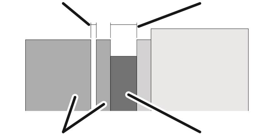
Magnet body and anchor plate
Brake rotor with brake lining
The air gap between the magnet body and the anchor plate must be measured to check the brake.
The air gap on the brake is measured through an opening in the side of the brake. The brake does not have to be disassembled.
Overview:
|
Air gap (between magnet body and anchor plate) |
Brake lining thickness |
|
| |
|
Magnet body and anchor plate |
Brake rotor with brake lining |
|
Dimension |
Value |
|
Maximum air gap |
0.95 mm |
|
Air gap when new |
0.35 mm |
If the air gap is wider than permitted, the brake rotor must be replaced.
If the width of the air gap is within the permitted range but usage behaviour leads to the expectation that the air gap will be wider than permitted before the next regular inspection, the brake rotor must be replaced now.
|
|
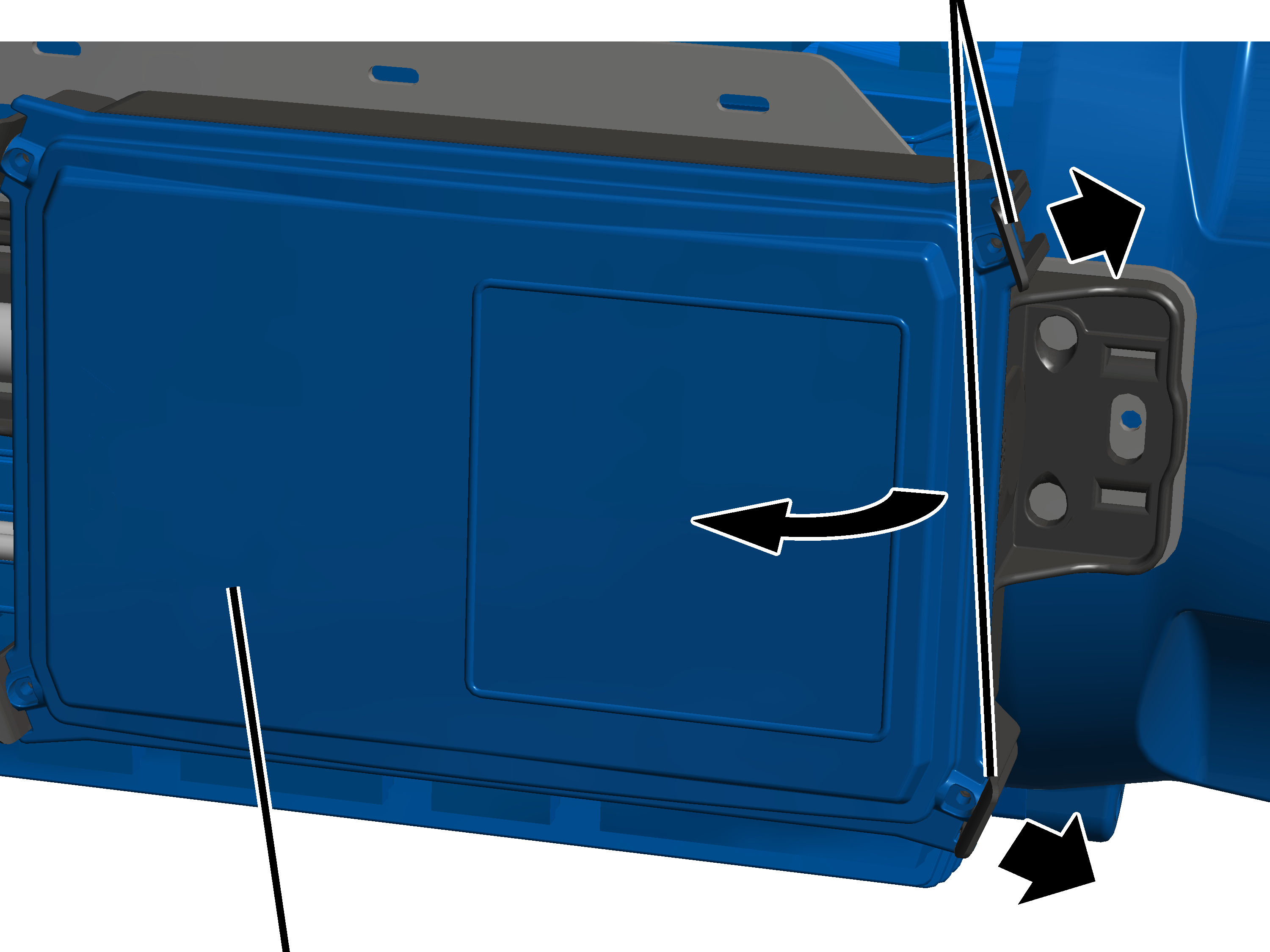
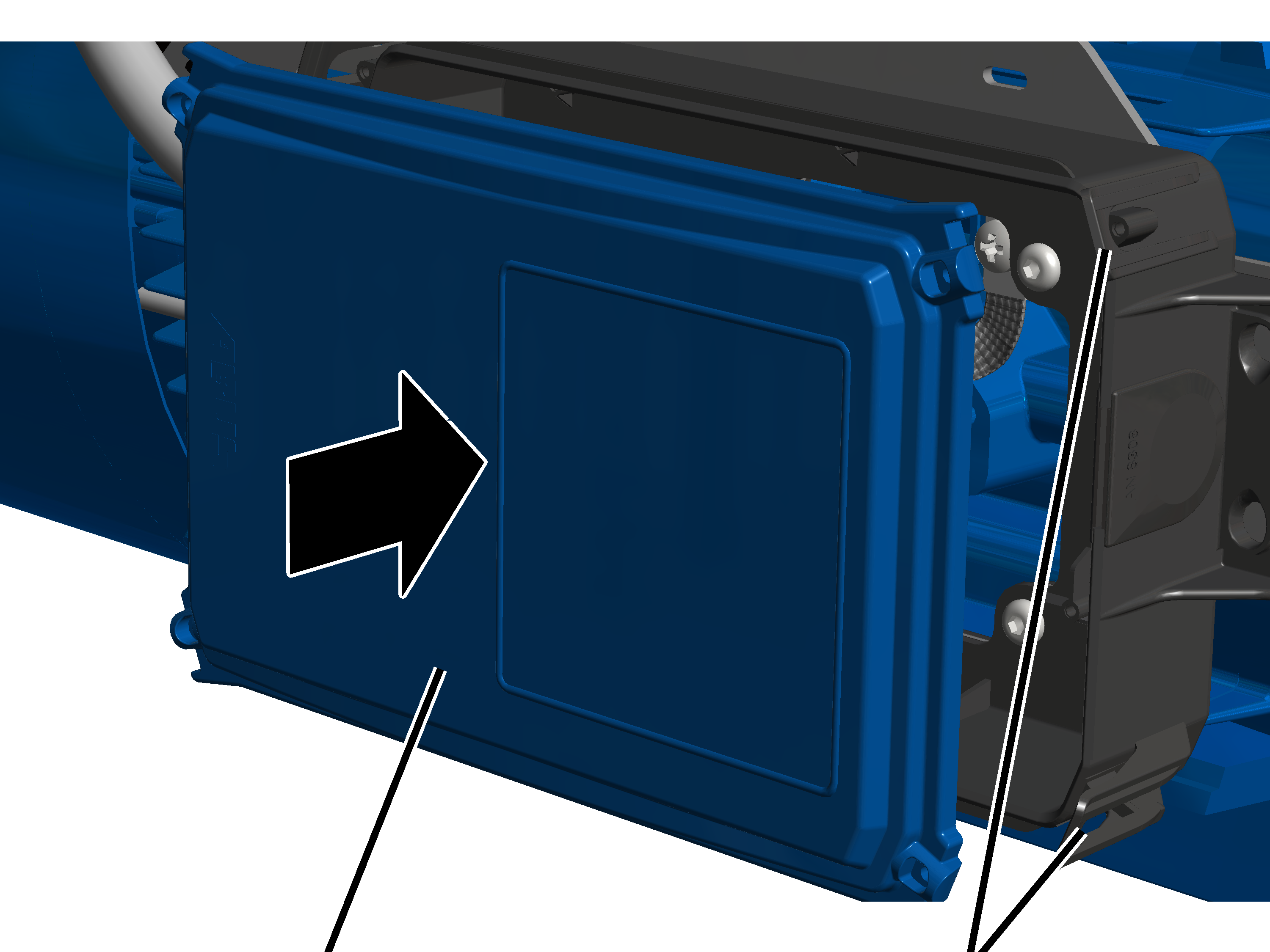
Clip fasteners |
|
| |
|
Cover |
|
 Lightly push the two clip
fasteners one one side slightly outwards.
Lightly push the two clip
fasteners one one side slightly outwards.
At the same time, pull the cover
on this side away from the housing.
|
| |
|
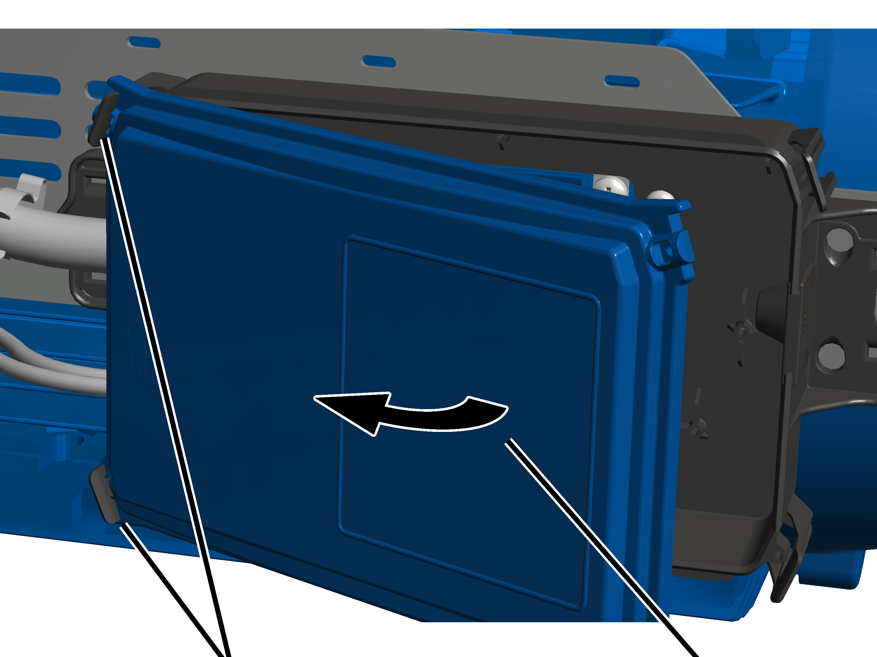
Clip fasteners |
Cover |
 Tilt the cover to the side until
it is almost perpendicular to the housing.
Tilt the cover to the side until
it is almost perpendicular to the housing.
● The lid automatically releases from the clip fasteners on the other side when tilted.
Put the cover aside.
|
|
Danger from electric shock! Even after the crane has been switched off, life-threatening high voltages are present in the frequency converter and hoist drive. Before working on the hoist drive, detach the connection cable of the hoist drive. |
|
|
Do not allow the fan cover to hang from the connection cable! If the fan cover with auxiliary fan hangs on the connection cable, it can break, since the fan cover with auxiliary fan is very heavy. Detach the plug-in connection in the connector housing and pull out the connection cable so that you can lay the fan cover aside during the assembly. |
|
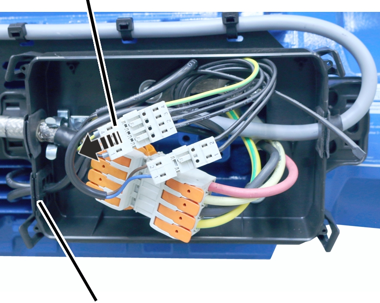
Auxiliary fan connector |
|
|
| |
|
Cable bushing |
|
Disconnect the auxiliary fan
connector.
Pull the connection cable of the
auxiliary fan out of the cable bushing.
The cable bushing is slotted in from above. This makes it easy to pull the connection cable out.
|
|
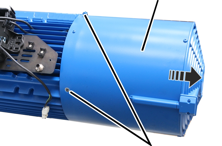
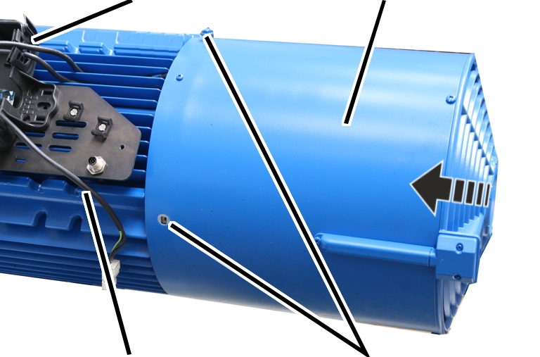
Fan cover |
|
| |
|
|
Rib screws M6x10 |
Unscrew the rib screws M6x10 of
the fan cover.
Pull the fan cover off to the
rear.
|
|
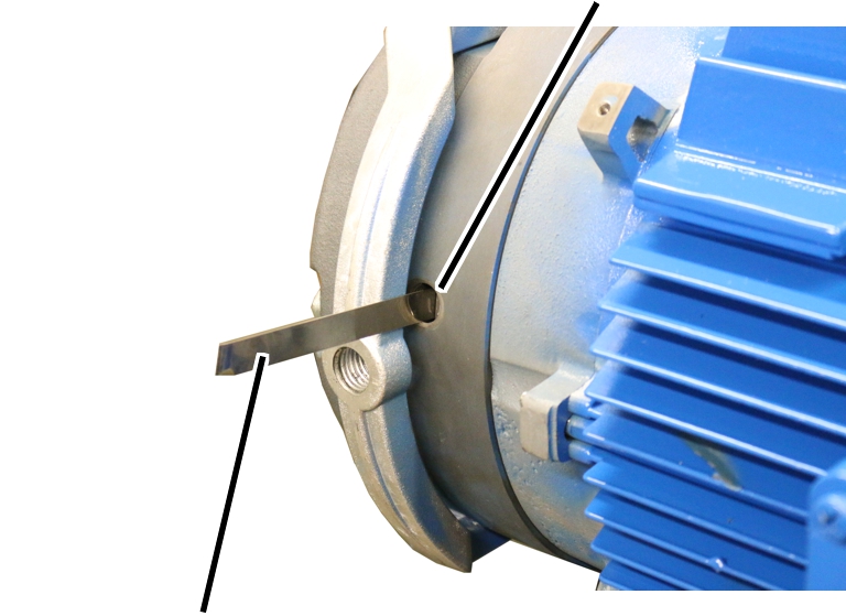
Opening in the brake |
|
| |
|
Feeler gauge |
|
Unscrew the screw plug on the
brake.
Push the feeler gauge at least
30 mm into the air gap from the side.
The air gap can only be measured reliably from a depth of at least 30 mm.
If the air gap is larger than
0.95 mm: Change brake rotor. See Replacing the brake rotor on
the hoist drive.
The air gap on the brake cannot be adjusted or readjusted.
If the width of the air gap is within the permitted range but usage behaviour leads to the expectation that the air gap will be wider than permitted before the next regular inspection, the brake rotor must be replaced now.
Screw the screw plug into the
opening on the brake.
If the hoist drive has been
braked 500 times via emergency stop at double lifting speed (200 Hz): Replace
the brake rotor. See Replacing the brake rotor on
the hoist drive.
During an emergency stop, the total energy of the lifting movement is absorbed by the brake. This causes the condition of the brake lining to deteriorate, which is why the brake rotor must be replaced after 500 applications of the brake.
|
Cable bushing |
Fan cover |
|
| |
|
Connection cable of the auxiliary fan |
Rib screws M6x10 |
Attach the fan cover with
built-in auxiliary fan.
Tighten the fan cover with M6x10
rib screws. 19 Nm.
Push the auxiliary fan
connection cable through the suitable cable bushing.
The cable bushing is slotted in from above so that the connection cable can be easily pushed in.
Insert the connector from the
auxiliary fan.
|
| |
|
Cover |
Clip fasteners |
Place all four corners of the
cover onto the housing.
Press the cover into all four
locking clips at the same time until they snap into place.