Danger from electric shock!
Even after the crane has been switched off, life-threatening high voltages are present in the frequency converter and hoist drive.
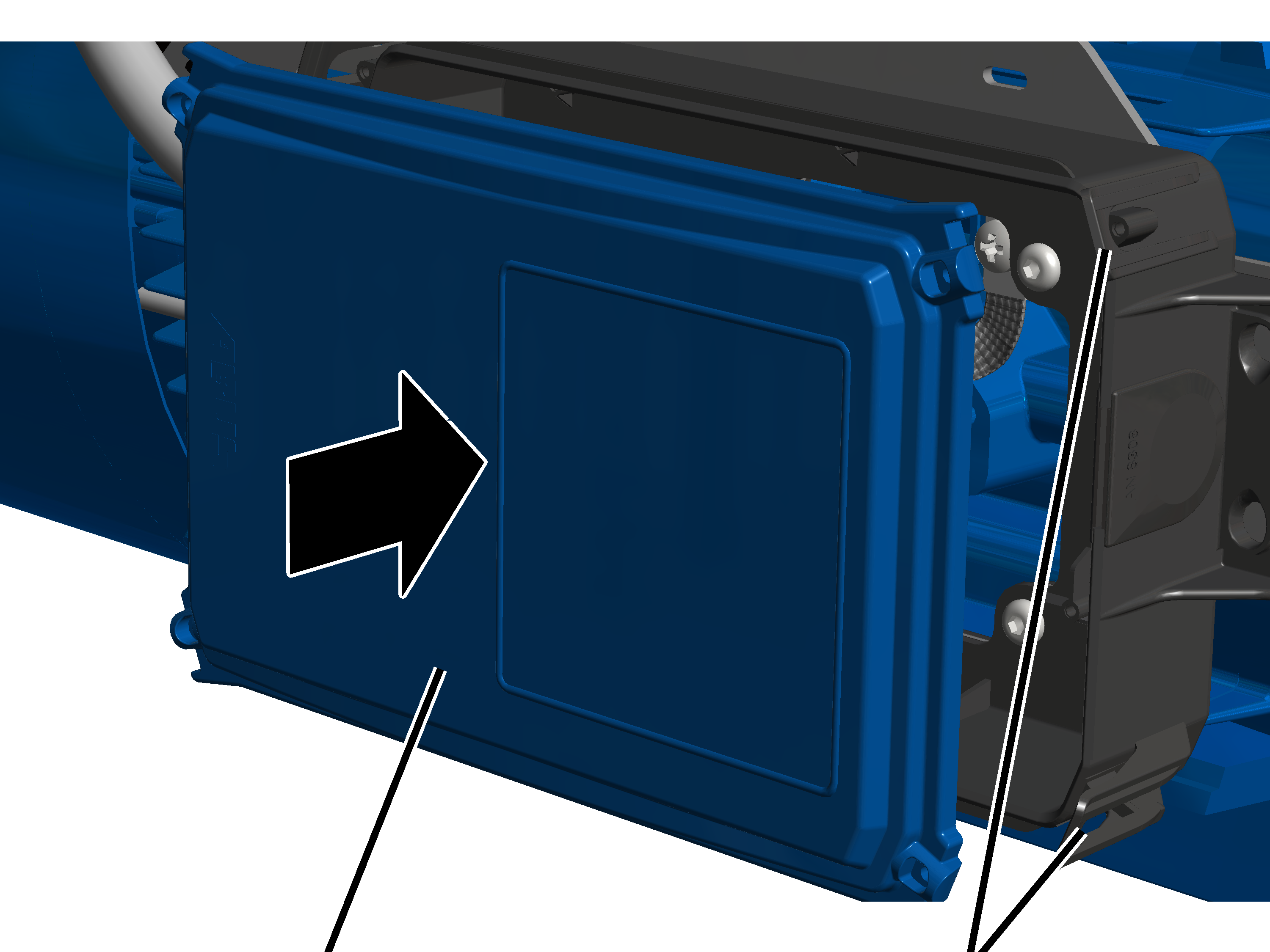
Before working on the hoist drive, detach the connection cable of the hoist drive.
If the air gap on the hoist drive is wider than permitted, the brake rotor must be replaced.
|
|
Danger from electric shock! Even after the crane has been switched off, life-threatening high voltages are present in the frequency converter and hoist drive. Before working on the hoist drive, detach the connection cable of the hoist drive. |
|
|
Do not allow the fan cover to hang from the connection cable! If the fan cover with auxiliary fan hangs on the connection cable, it can break, since the fan cover with auxiliary fan is very heavy. Detach the plug-in connection in the connector housing and pull out the connection cable so that you can lay the fan cover aside during the assembly. |
|
Auxiliary fan connector |
|
|
| |
|
Cable bushing |
|
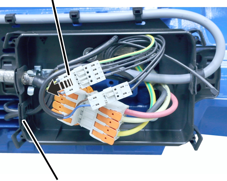
 Disconnect the auxiliary fan
connector.
Disconnect the auxiliary fan
connector.
Pull the connection cable of the
auxiliary fan out of the cable bushing.
The cable bushing is slotted in from above. This makes it easy to pull the connection cable out.
|
|
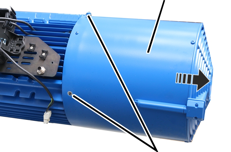
Fan cover |
|
| |
|
|
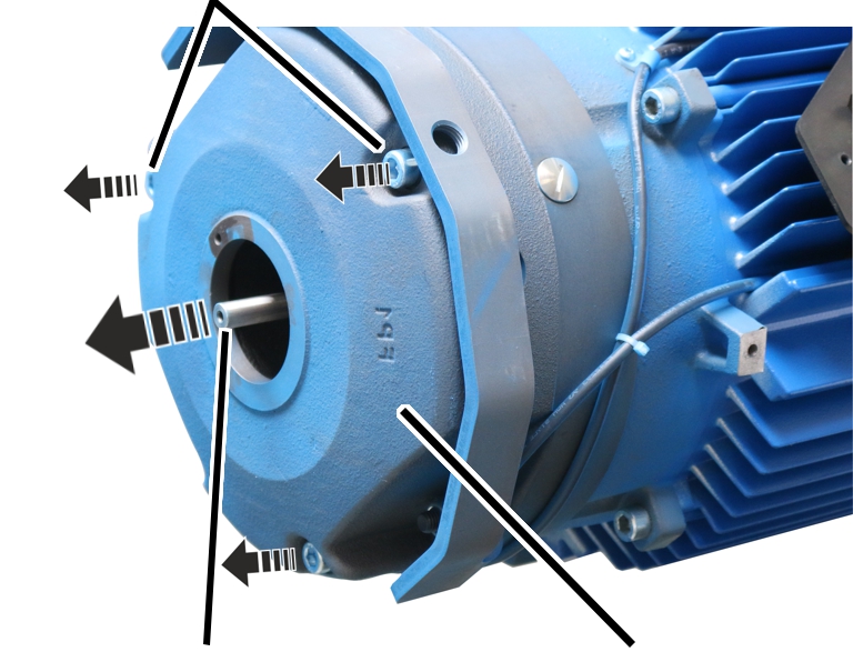
Rib screws M6x10 |
Unscrew the rib screws M6x10 of
the fan cover.
Pull the fan cover off to the
rear.
|
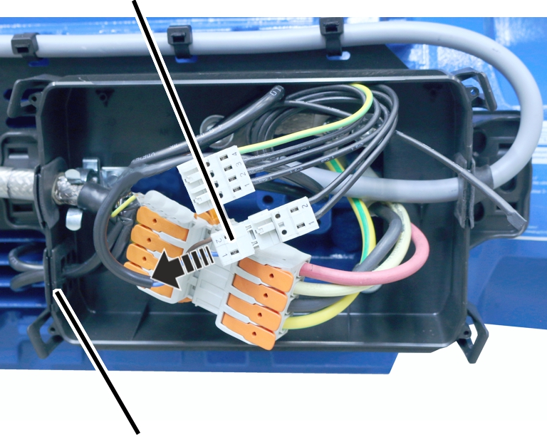
Plug-in connection of brake |
|
|
| |
|
Cable bushing |
|
Disconnect the brake
connector.
Pull the brake connection cable
out of the cable bushing.
The cable bushing is slotted in from above. This makes it easy to pull the connection cable out.
The incremental rotary encoder on the motor shaft must be dismantled in order to dismantle the brake. It is not sufficient to dismantle the spring element and/or the torque support
|
Spring element |
Torque support |
|
| |
|
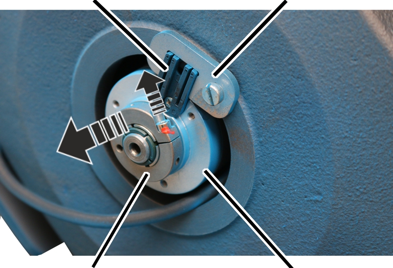
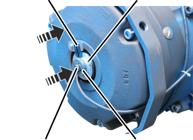
Clamping ring |
Incremental rotary encoder |
Loosen the hexagon head screw
M3x10 on the clamping ring.
Do not dismantle the spring
element and/or torque support.
Pull the incremental rotary
encoder off the motor shaft to the rear.
● The spring element is mounted on the incremental rotary encoder and slips out of the torque support.
|
|
Danger due to the heavy weight of the component! The magnet body is heavy (about 30 kg). If it is unscrewed without being secured, it can fall down and injure people. Secure the magnet body before unscrewing it. |
|
|
Damage to the motor shaft! The magnet body is heavy (about 30 kg). If it is supported on the thin end of the motor shaft, the motor shaft may break or bend. Secure the magnet body before unscrewing it. |
|
Fillister-head screws |
|
|
| |
|
Motor shaft |
Magnet body |
Remove the fillister-head screws
M10x110 (3x).
Secure the magnet body so that it
does not fall down or get caught on the motor shaft.
Take off the magnet body.
|
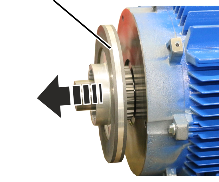
Brake rotor |
|
|
| |
Pull the brake rotor from the
hub.
Put new brake rotor onto the
hub.
|
Spring element |
Incremental rotary encoder |
|
| |
|
Motor shaft |
Clamping ring |
Place the magnet body on the
motor shaft.
Do not support the magnet body on the motor shaft.
Tighten the magnet body with
cheese head screws M10x110 (3x). 45 Nm.
Plug the incremental rotary
encoder onto the motor shaft.
Turn the incremental rotary
encoder so that the spring element slips into the torque support and is held
without play.
Tighten fillister-head screw
M5x10 on the clamping ring and secure with threadlocker. 1 Nm.
Place the brake connection cable
in the connector housing and push it through the cable bushing.
The cable bushing is slotted in from above so that the connection cable can be easily pushed in.
|
Cable bushing |
Fan cover |
|
| |
|
Connection cable of the auxiliary fan |
Rib screws M6x10 |
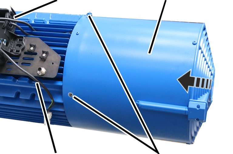
Attach the fan cover with
built-in auxiliary fan.
Tighten the fan cover with M6x10
rib screws. 19 Nm.
Push the auxiliary fan
connection cable through the suitable cable bushing.
The cable bushing is slotted in from above so that the connection cable can be easily pushed in.
Insert the connector from the
auxiliary fan.
|
| |
|
Cover |
Clip fasteners |
Place all four corners of the
cover onto the housing.
Press the cover into all four
locking clips at the same time until they snap into place.