If the trolley towing arm has not been installed yet, continue here. Otherwise, skip this section.
The trolley towing arm is installed above the hoist panel. It pulls the electrical cables for the trolley power supply (festoon cable system or energy chain) and the cross-type limit switch of the trolley travel limit switch back and forth parallel to the trolley.
The trolley towing arm must be installed differently, depending on the main girder (I-beam or box girder) and the type of power supply (festoon cable system or energy chain).
|
|
Trolley towing arm with normal-height main girders (primarily box girders) and energy chain. See Assemble trolley towing arm for normal-height main girders, and then Installing energy chain on carrying tube.
|
|
Trolley towing arm with low main girders (primarily I-beams) and energy chain. See Assemble trolley towing arm for low main girders and then Installing energy chain on carrying tube.
|
|
Trolley towing arm in festoon cable system. See Assembling trolley towing arm for festoon cable system.
|
Carrying tube |
|
|
| |
|
Trolley towing arm |
Rectangular pipe clamp |
 Slide the rectangular pipe clamp
onto the vertical part of the trolley towing arm.
Slide the rectangular pipe clamp
onto the vertical part of the trolley towing arm.
Turn square tube so that the
drill holes point to the main girders later.
Slide the carrying tube into the
rectangular pipe clamp.
Loosely screw in M8 rib nuts
(4x) onto the rectangular pipe clamp. The square tube will have to be shifted
later.
On both ends of the trolley towing arm:
|
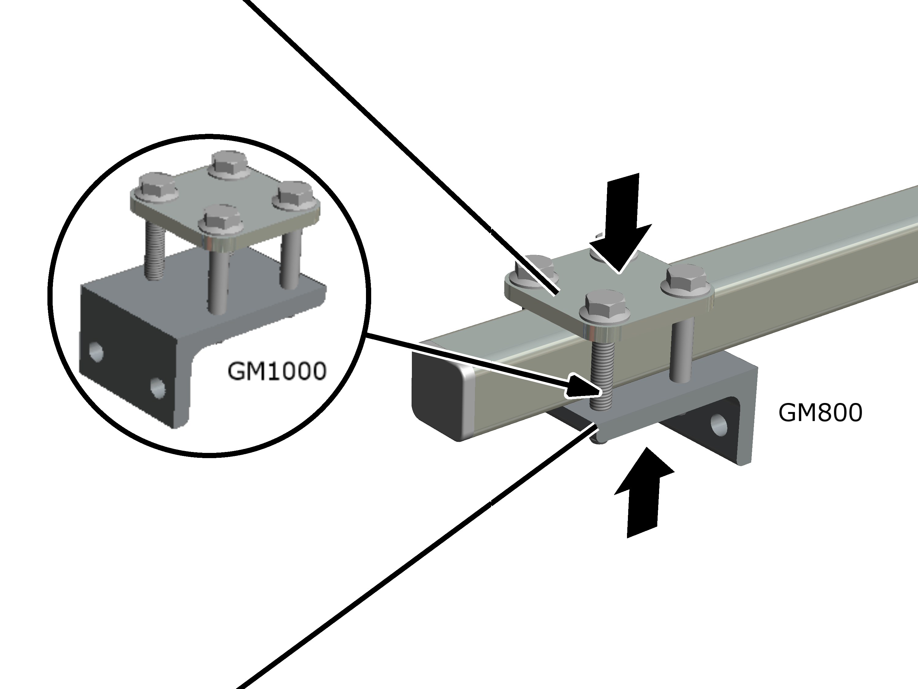
Plate |
|
|
| |
|
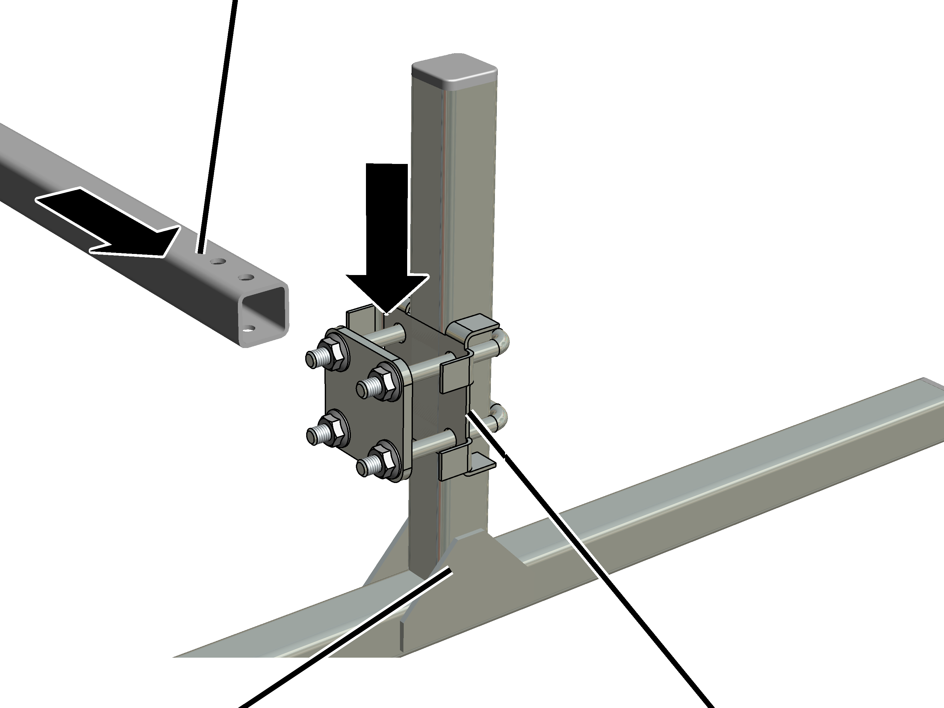
Mounting bracket |
|
Mounting bracket and plate
pre-installed with M8x50 rib screws.
On GM800: Turn the unit so that
the mounting bracket points outward later
On GM1000: Turn the unit so that
the mounting bracket points inward later.
Screw unit together loosely.
|
| |
|
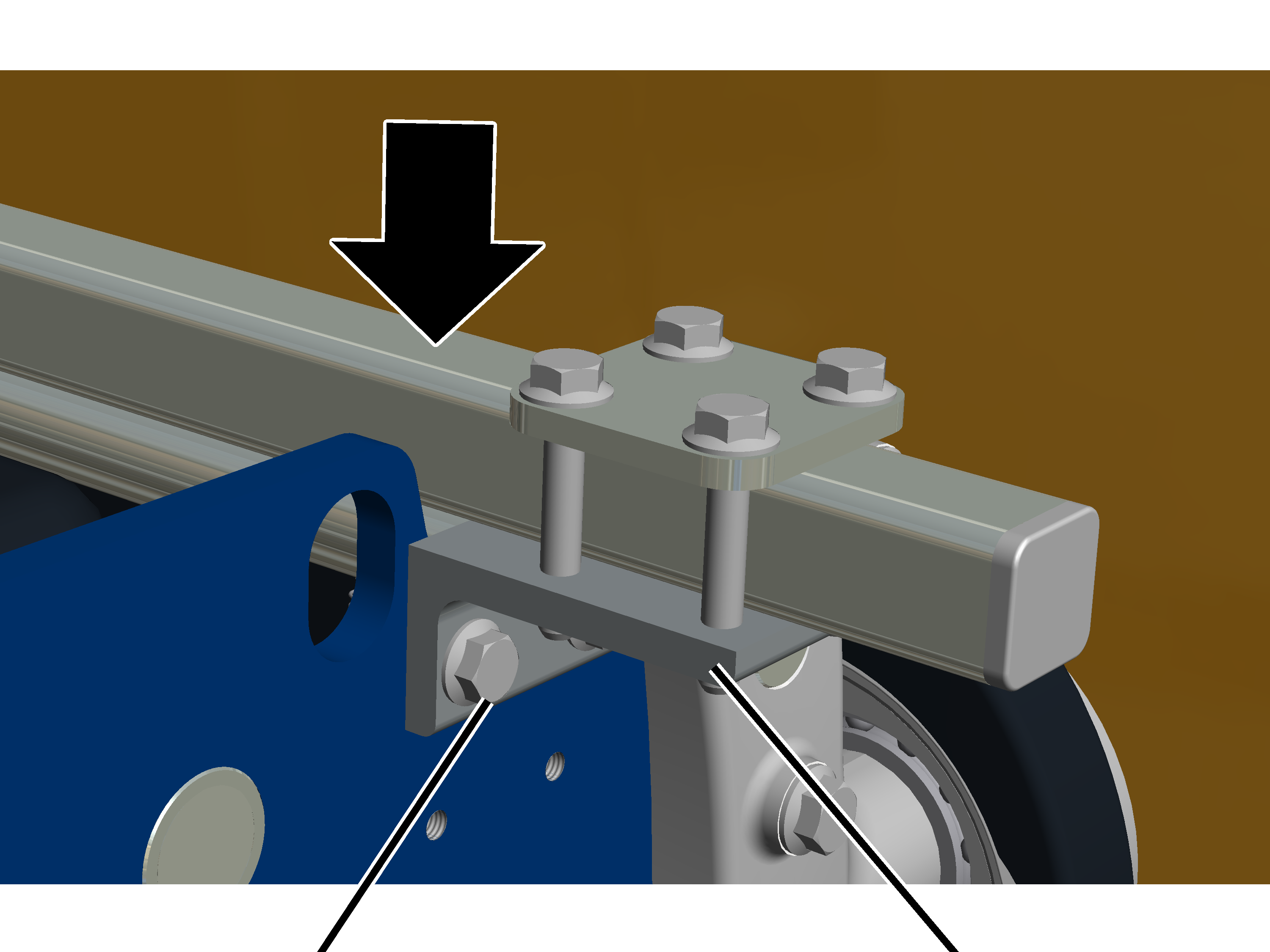
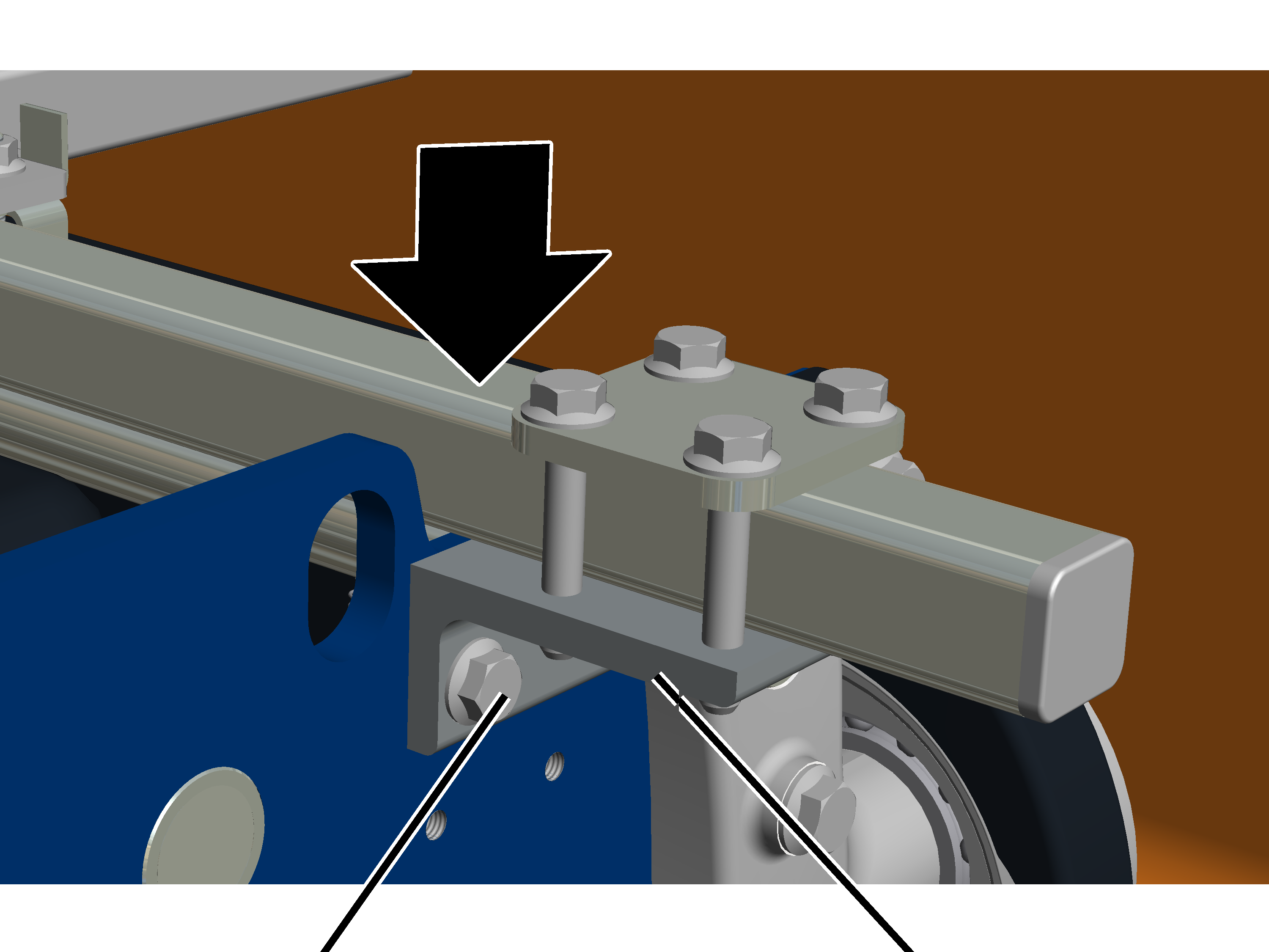
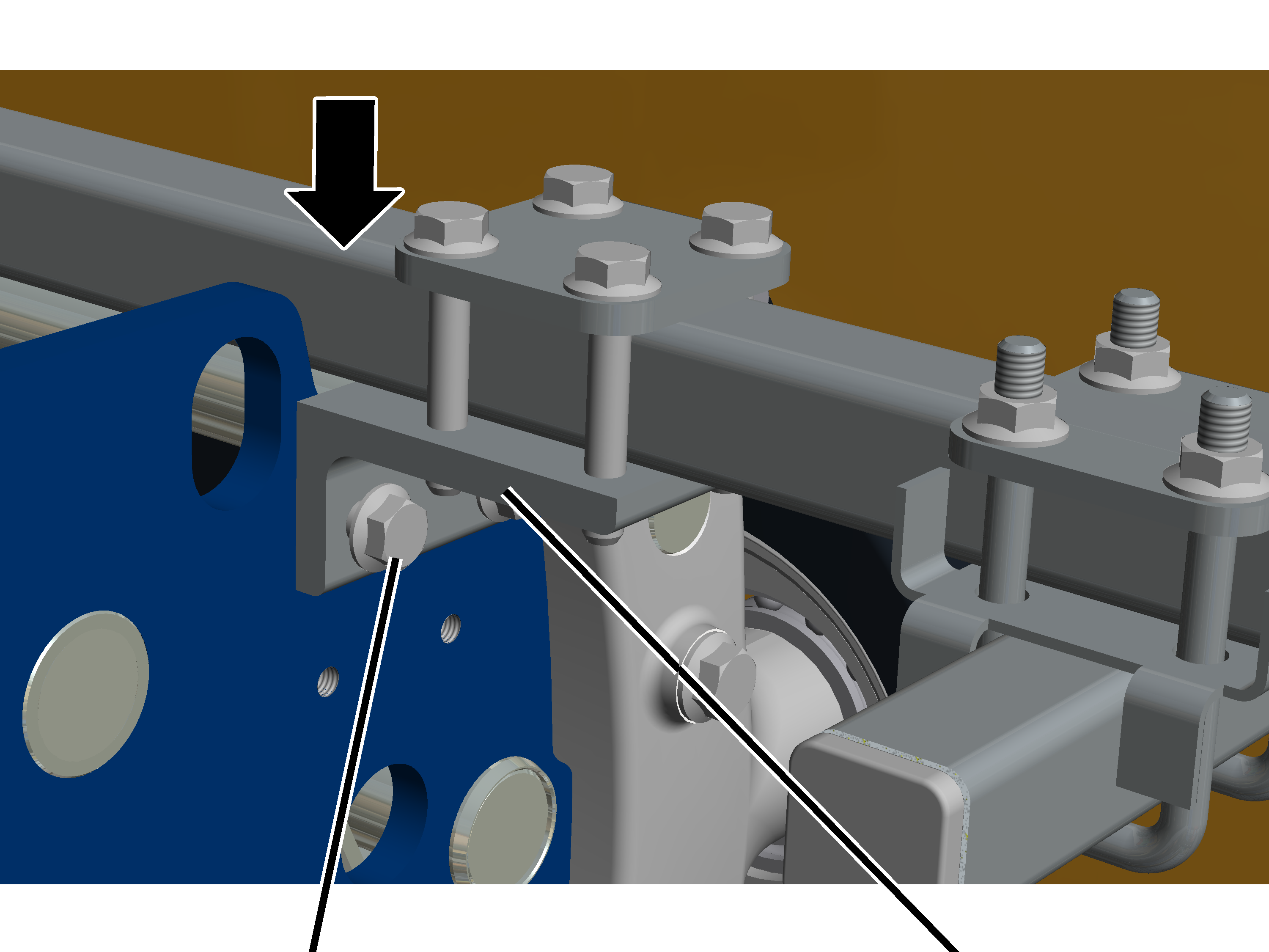
Rib screw |
Mounting bracket |
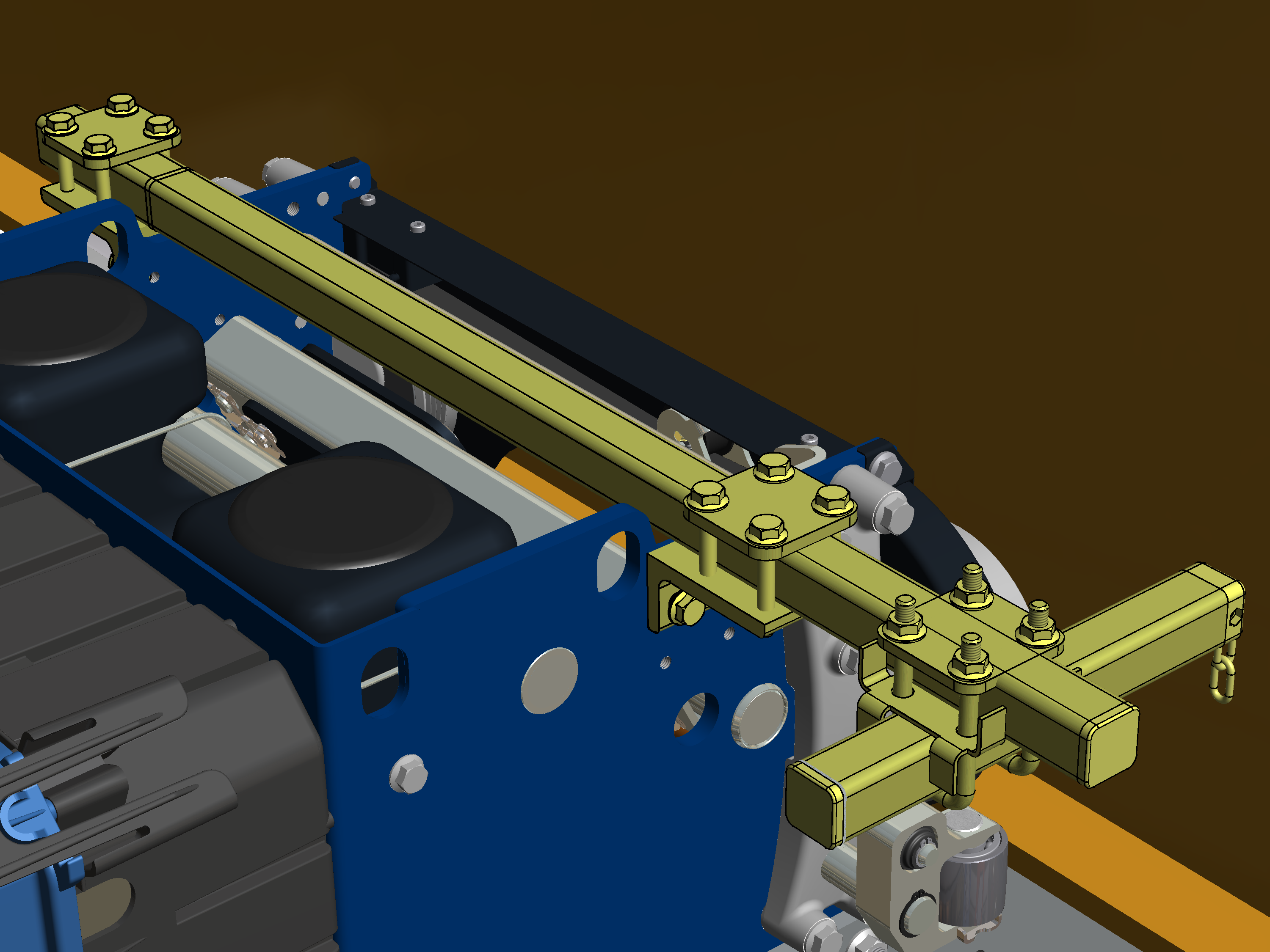
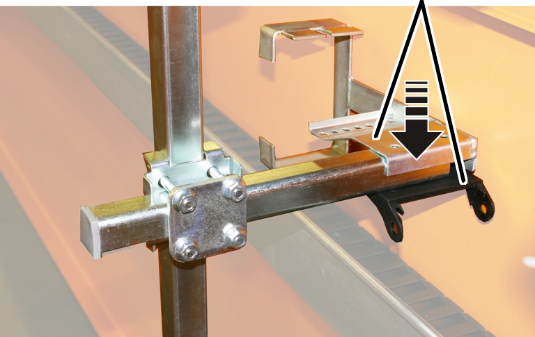
Place the trolley towing arm
from above onto the trolley frame on the counterweight side.
On GM800: The mounting brackets are placed onto the sides of the trolley frame from the outside (see picture).
On GM1000: The mounting brackets point inward, however they are placed and screwed onto the side panel of the trolley frame from outside with the side of the mounting bracket.
Screw on the mounting brackets
with the M8x20 (2x per mounting bracket) rib screws until they are hand-tight.
25 Nm
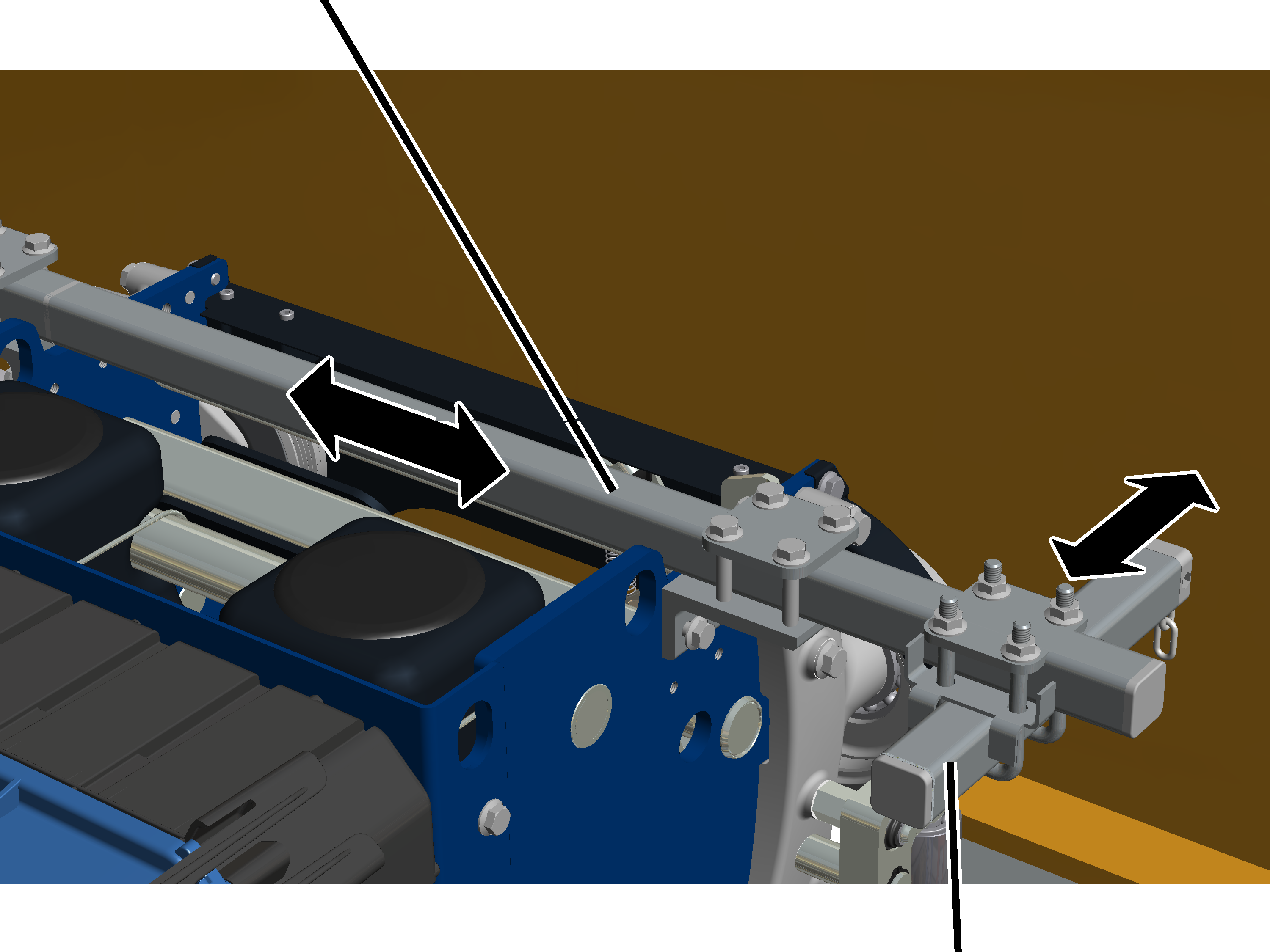
|
|
Carrying tube |
|
| |
|
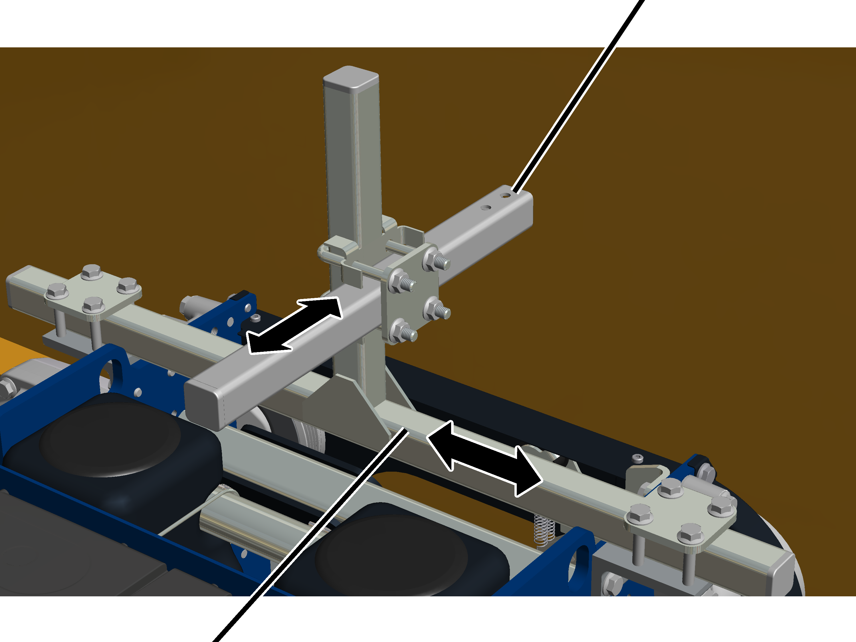
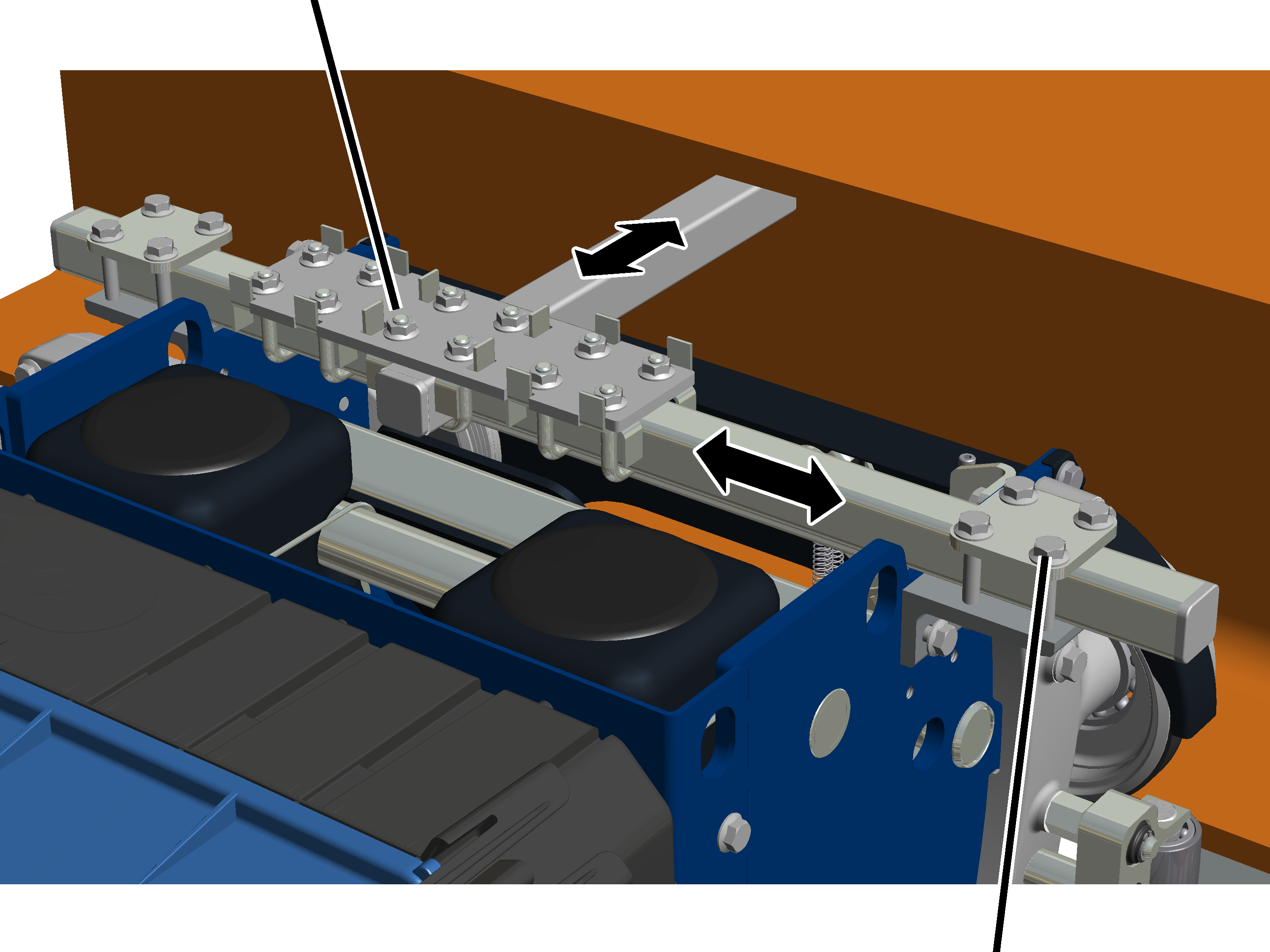
Trolley towing arm |
|
 Shift trolley towing arm
sideways (parallel to the main girder) as centred as possible to the wire rope
hoist.
Shift trolley towing arm
sideways (parallel to the main girder) as centred as possible to the wire rope
hoist.
Shift the carrying tube
crosswise (vertical to main girder) into the necessary position.
For more details: See assembly instructions of the energy chain.
Tighten M8 rib nuts (12x) and
M8x50 rib screws (8x). 25 Nm
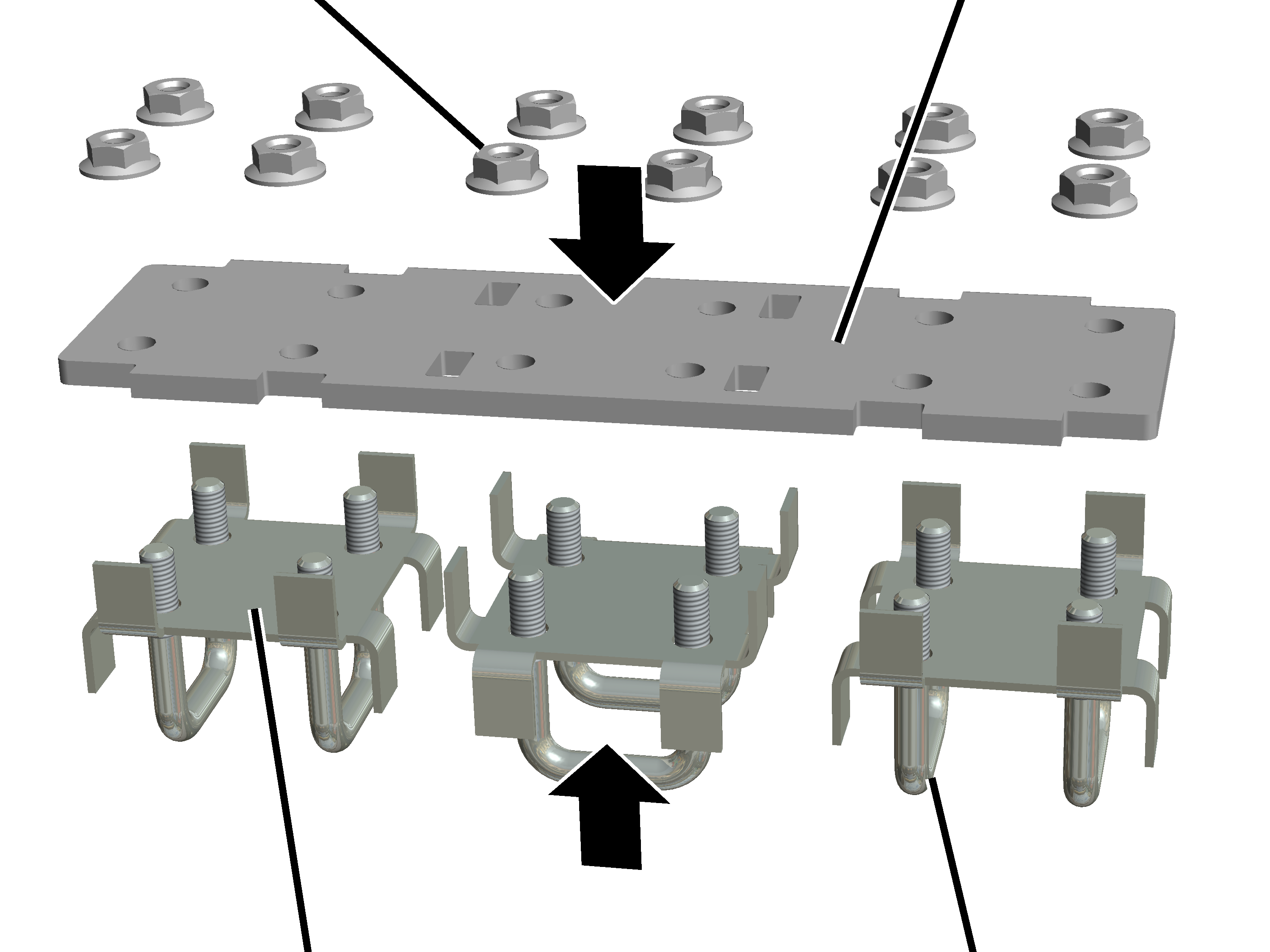
|
M8 rib nuts |
Metal plate |
|
| |
|
Rectangular pipe clamp |
Threaded bracket |
Loosely screw together plate,
rectangular pipe clamp (3x) and threaded bracket (6x) with rib nuts (12x) as
shown in the picture.
|
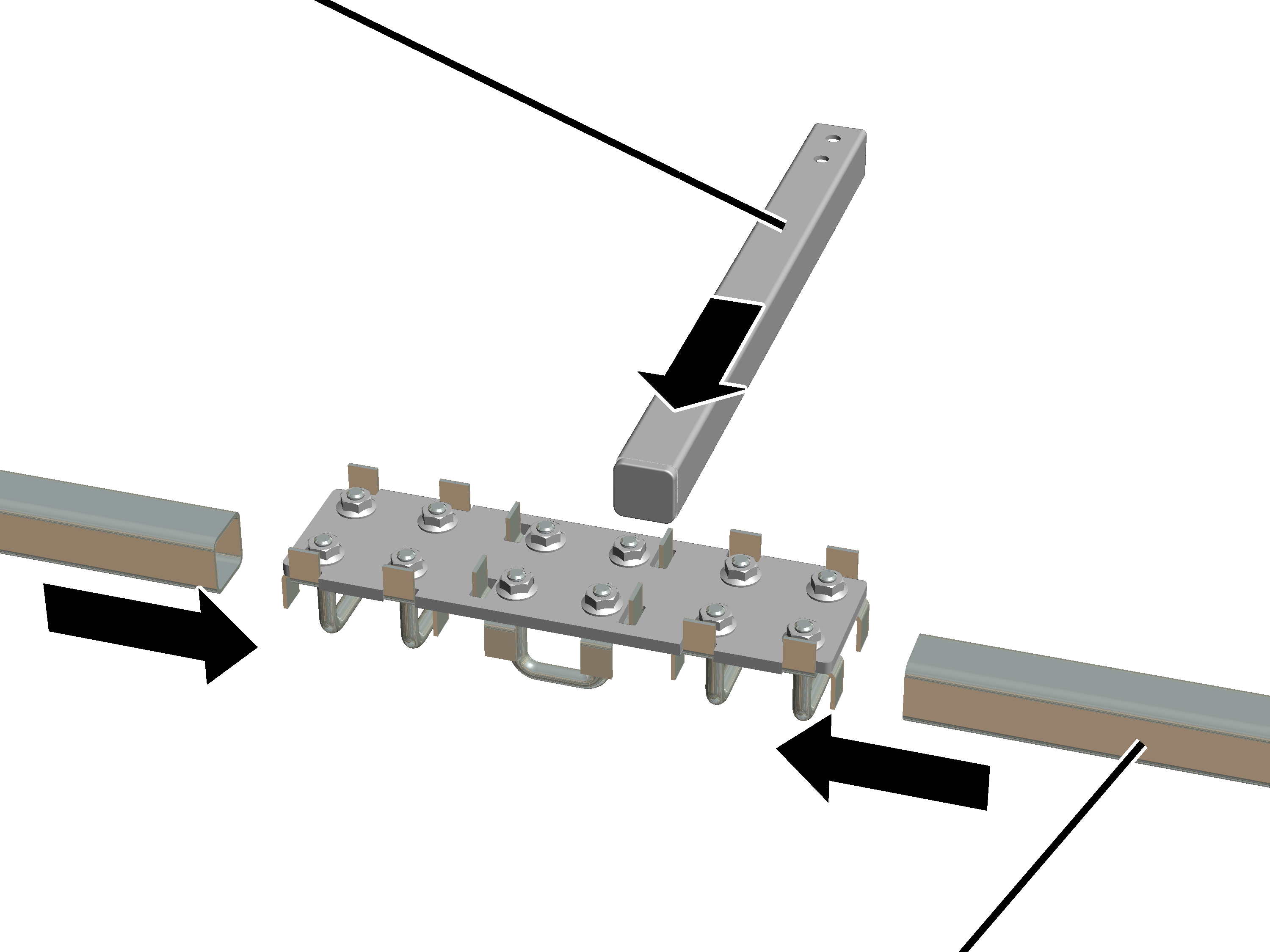
Carrying tube |
|
|
| |
|
|
Square tube |
Turn square tube so that the
drill holes point to the main girders later.
Slide the carrying tube into the
threaded bracket on the long side.
Slide square tube (2x) into the
threaded bracket on the short side, until it hits the already installed carrying
tube.
Loosely screw on M8 rib nuts
(12x). The square tubes must be shifted later.
On both sides:
|
Plate |
|
|
| |
|
|
Mounting bracket |
Mounting bracket and plate pre-installed with M8x50 rib
screws.
On GM800: Turn the unit so that
the mounting bracket points outward later
On GM1000: Turn the unit so that
the mounting bracket points inward later.
Screw unit together loosely.
|
| |
|
Rib screw |
Mounting bracket |
Place
the trolley towing arm from above onto the trolley frame on the counterweight
side.
On GM800: The mounting brackets are placed onto the sides of the trolley frame from the outside (see picture).
On GM1000: The mounting brackets point inward, however they are placed and screwed onto the side panel of the trolley frame from outside with the side of the mounting bracket.
Screw on the mounting brackets
with the M8x20 (2x per mounting bracket) rib screws until they are hand-tight.
25 Nm
|
Rib nuts |
|
|
| |
|
|
Rib screws |
Shift trolley towing arm
sideways (parallel to the main girder) as centred as possible to the wire rope
hoist.
Slide the trolley towing arm
crosswise (vertical to the main girder) into the necessary position.
For more details: See assembly instructions of the energy chain.
Screw M8 rib nuts (12x) tight.
15 Nm.
Screw in the rib screws M8x50
(8x). 25 Nm
The energy chain is fastened to the horizontal carrying tube.
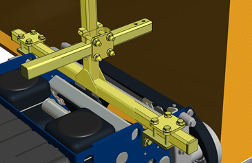
|
|
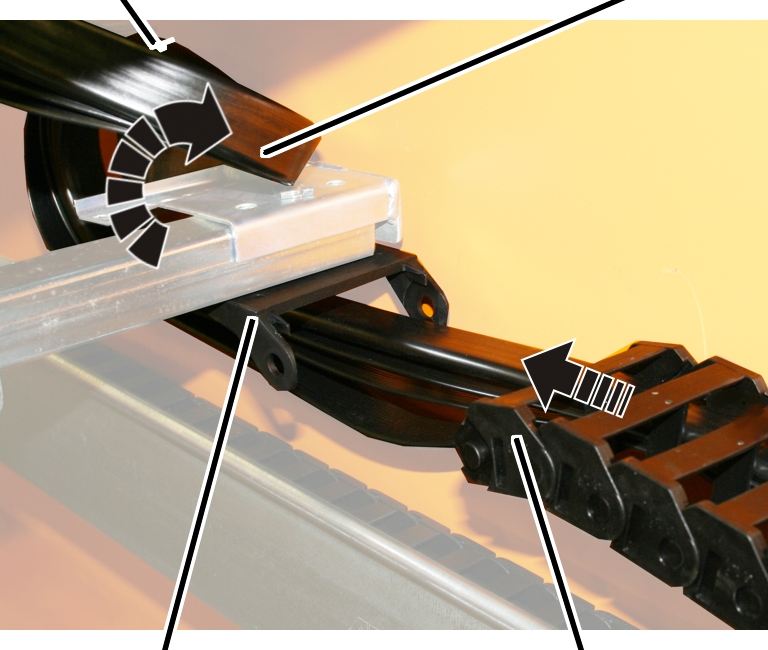
Individual components of the energy chain |
|
| |
|
|
|
|
Cable tie |
Flat cable | |
|
| ||
|
Connection element |
Energy chain | |
Lead through the flat cable from
the energy chain and guide in a curve around the deflection bracket.
Fasten the flat cable with cable
ties to the upper section of the deflection bracket.
Insert the energy chain into the
connection element and click into place.
On both sides of the square tube:
|
Plate |
|
|
| |
|
Mounting bracket |
|
Mounting bracket and plate
pre-installed with M8x50 rib screws.
On GM800: Turn the unit so that
the mounting bracket points outward later
On GM1000: Turn the unit so that
the mounting bracket points inward later.
Screw unit together loosely.
On the opposite side of the festoon cable system's feed unit:
|
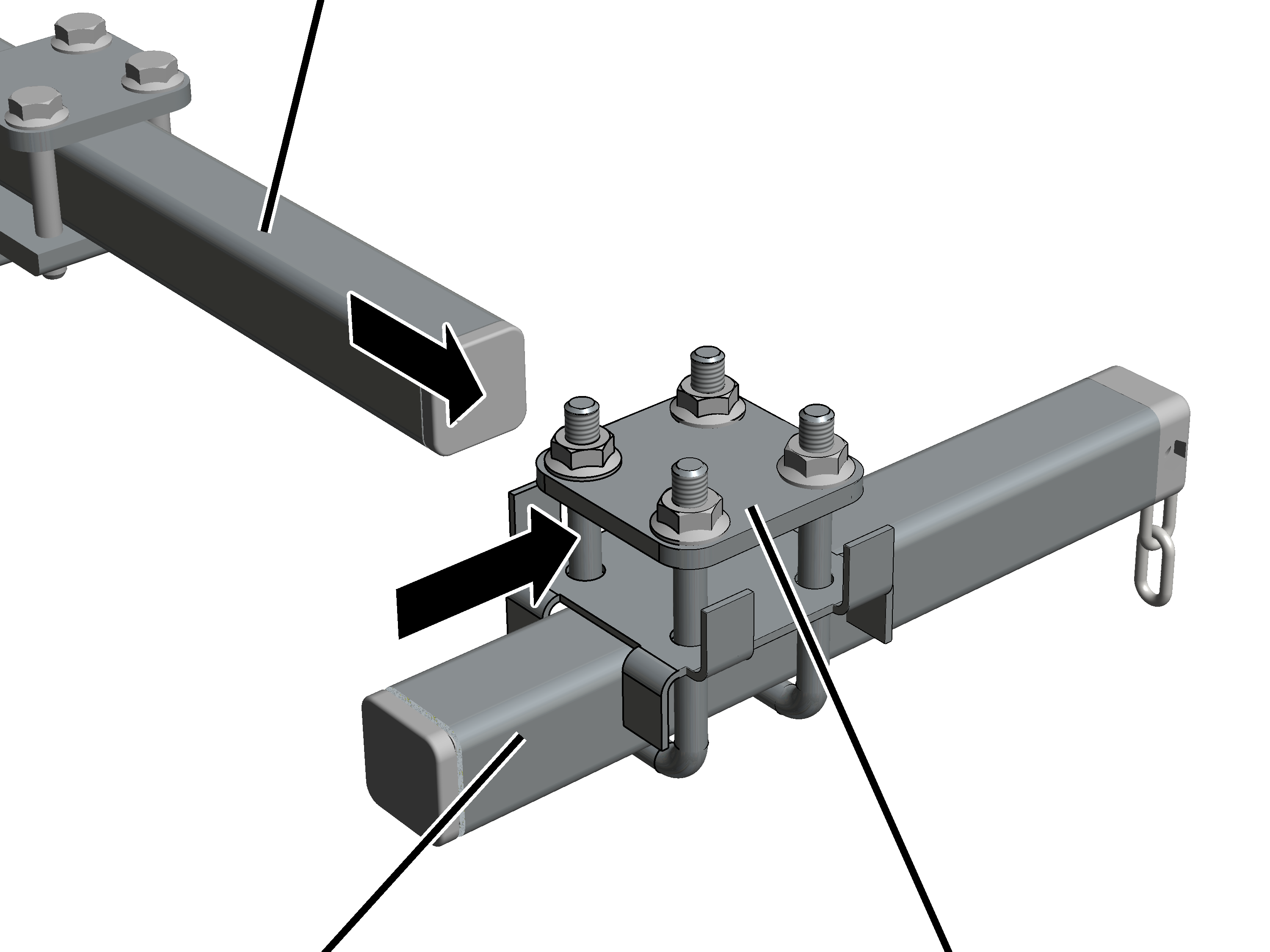
Square tube |
|
|
| |
|
Square tube |
Pipe clamp |
Slide the pipe clamp with
rectangular pipe clamp onto the short square tube.
Slide long square pipe into the
pipe clamp.
Loosely screw in M8 rib nuts
(4x) onto the pipe clamp. The square tubes must be shifted later.
For festoon cable system with chain:
|
| |
|
Dowel |
Square tube |
Insert a dowel in the horizontal
or vertical square tube.
Insert a screw in the dowel and
screw in until the dowel sits tightly in the square tube.
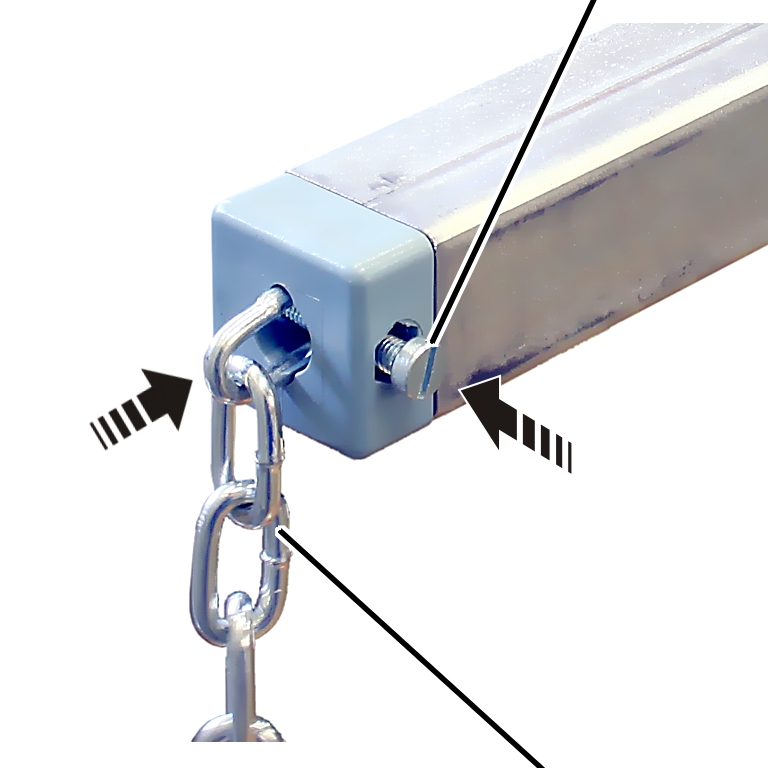
|
|
Fillister-head screw |
|
| |
|
|
Chain |
Insert the chain into the dowel
from the front.
Insert a fillister-head screw
laterally into the dowel and screw until hand-tight with a self-locking nut.
|
| |
|
Rib screw |
Mounting bracket |
Place the trolley towing arm
from above onto the trolley frame on the counterweight side.
On GM800: The mounting brackets are placed onto the sides of the trolley frame from the outside (see picture).
On GM1000: The mounting brackets point inward, however they are placed and screwed onto the side panel of the trolley frame from outside with the side of the mounting bracket.
Screw on the mounting brackets
with the M8x20 (2x per mounting bracket) rib screws until they are hand-tight.
25 Nm
|
Square tube |
|
|
| |
|
|
Short square tube |
Move the long square tube
(parallel to main girder) into the desired position.
Move the short square tube
(vertical to main girder) into the desired position.
Screw M8 rib nuts (12x) tight.
15 Nm.
Screw in the rib screws M8x50
(8x). 25 Nm
Connect the chain or the square
tube with the cable carrier of the festoon cable system.