Rib nut M12
Hexagon head screw M12x40
in slot and in
pivot
If the wire rope hoist has not been installed yet, continue here. Otherwise, skip this section.
The wire rope hoist can be mounted to a main girder or I-beam from below when tipped and when it is in installed condition.
The pictures show the procedure on a GM 1000 modular wire rope hoist. The procedure on GM 800 does not differ significantly from this.
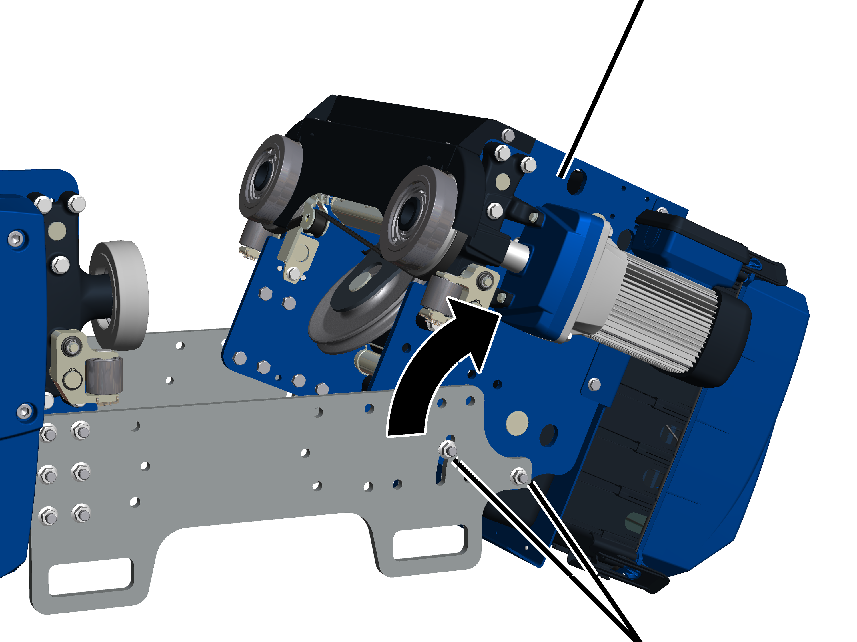
First the screws on the flange plate are unscrewed and removed so that the wire rope hoist can be tipped.
On both flange plates:
|
Rib nut M12 |
|
|
| |
|
Hexagon head screw M12x40 | |
 Place the wire rope hoist with
the flange plate onto a firm, elevated surface.
Place the wire rope hoist with
the flange plate onto a firm, elevated surface.
When tipping the counterweight side, the loosened half will later swivel downwards.
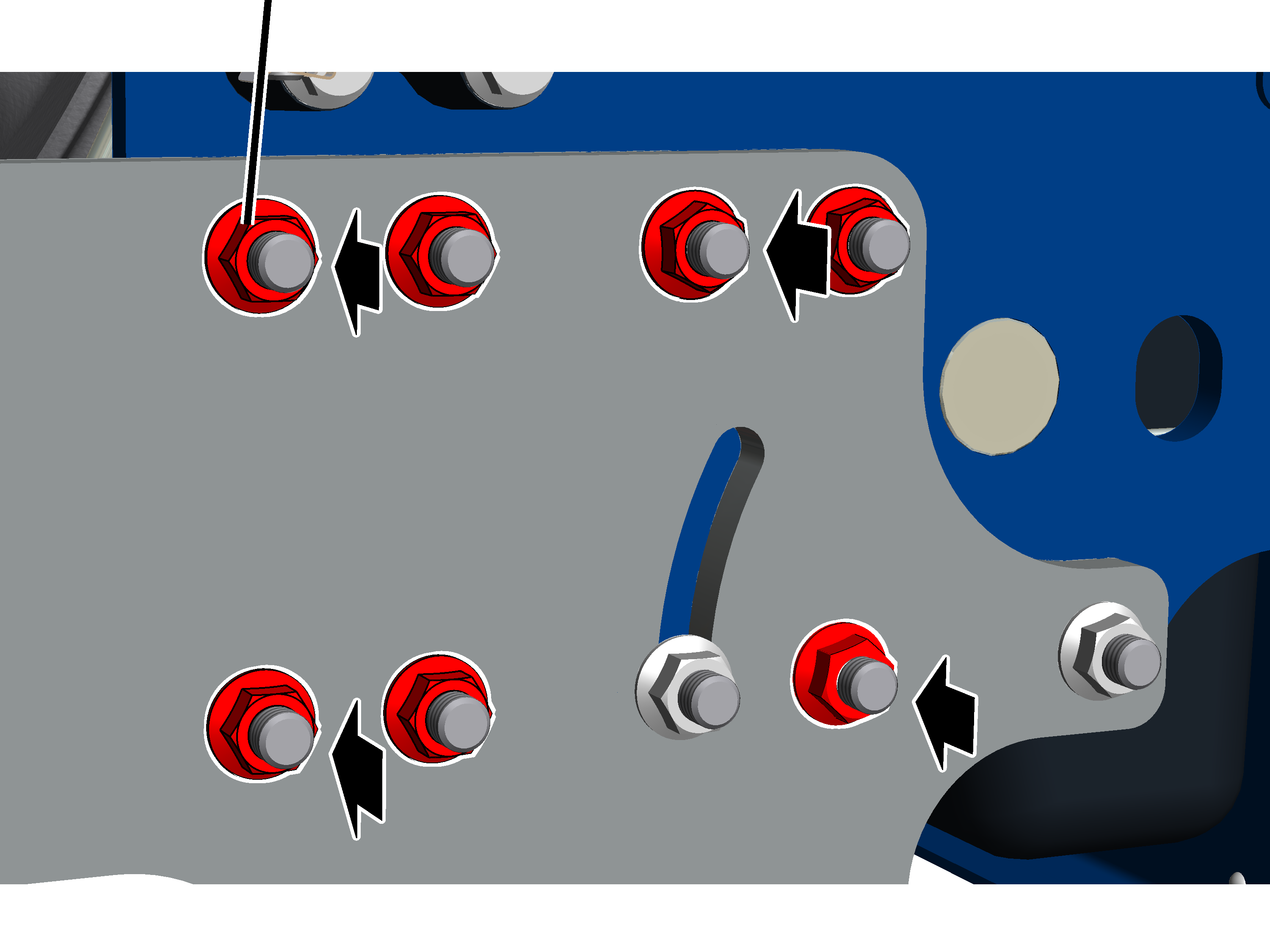
Leave M12 rib nuts tightly
screwed in the pivot and slot for now.
Loosen all other M12 rib nuts on
the counterweight side and remove the M12x40 hexagon head screws.
|
Size |
Screws on the counterweight side for each flange plate |
Screws on the drum side for each flange plate |
|
GM 800 |
4x 2x in the pivot and slot |
4x |
|
GM 1000 |
7x 2x in the pivot and slot |
6x |
|
|
Danger of crushing on trolley frame! Fingers can be crushed by moving parts when the counterweight side is tipped. Wear gloves. Hold the counterweight side in the upper area and slowly pull manually. |
|
|
The wire rope hoist's counterweight side |
|
| |
|
|
Hexagon head screw M12x40 in slot and in pivot |
Secure the wire rope hoist's
counterweight side, so that it cannot tip uncontrollably.
Loosen M12 rib nuts in pivot and
slot, but do not remove them.
Hold the counterweight side in the
upper area and tilt until hexagon head screw M12x40 has reached the end of
the slot.
Tighten M12 rib nuts in pivot
and slot. 85 Nm.
This ensures that the counterweight side does not tip accidentally during further installation.
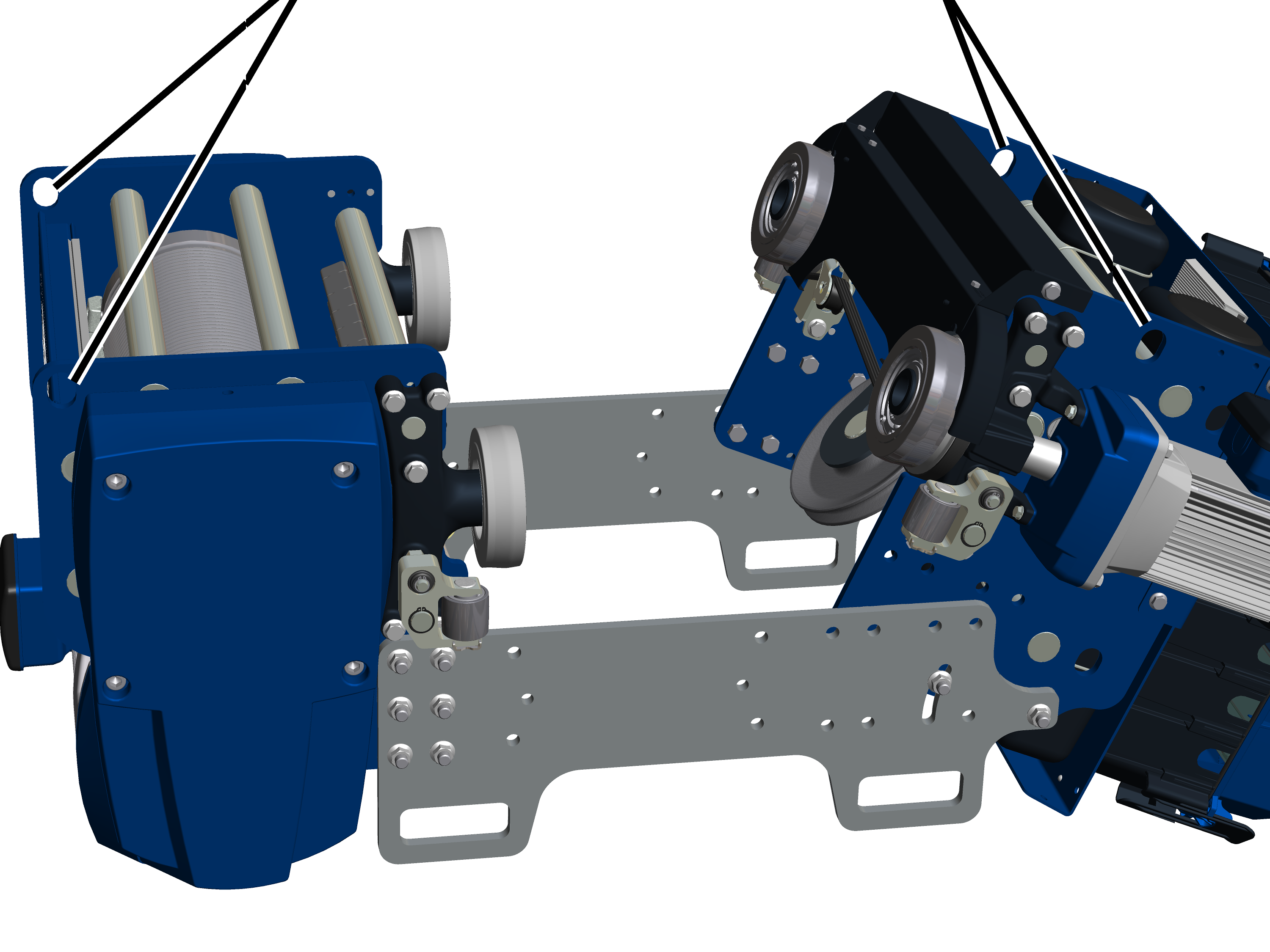
Now the wire rope hoist is brought under the main girder or single-rail trolley track from below, and placed on the bottom flange and/or lower flange.
|
Suspension eyelets drum side |
suspension eyelets counterweight side |
|
| |
Either:
Use suitable lifting tackle with
load hooks.
Hang all four load hooks in the
suspension eyelets on the wire rope hoist.
Observe the occupational health
and safety requirements, and raise the wire rope hoist.
Or:
Raise the wire rope hoist from
below by the flange plates.
|
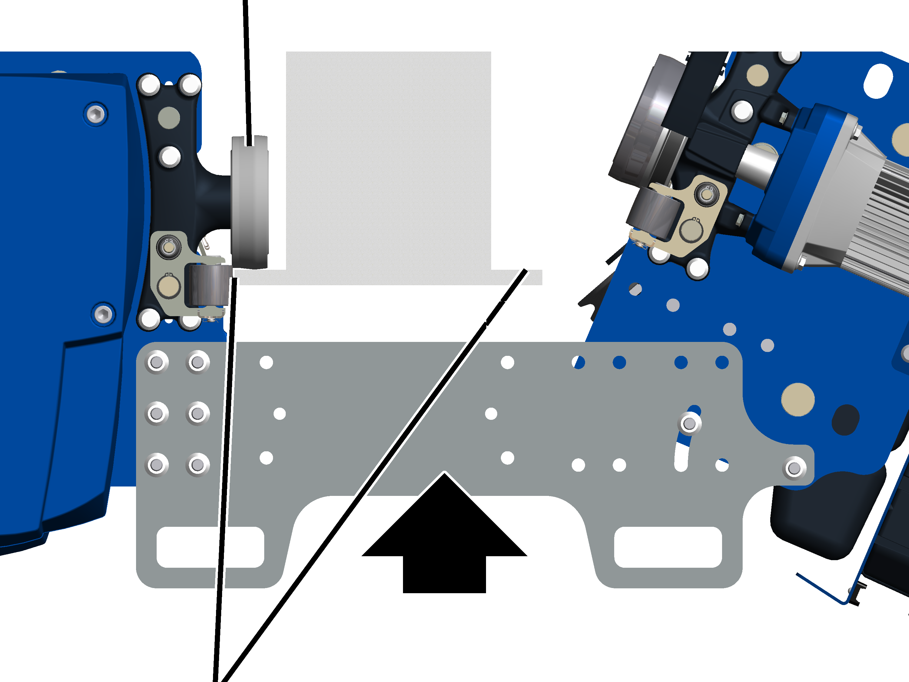
Wheels on drum side |
|
|
| |
|
Here: Lower flange, alternatively bottom flange |
|
|
|
Do not damage guide rollers! The guide rollers can be damaged when the guide rollers of the wire rope hoist hit against the main girder. Position the wire rope hoist precisely and move it carefully. |
Move the wire rope hoist in such
a way that the drum side is on the side across from the trolley power supply.
Lift the wire rope hoist from
below by the main girders and raise until the wheels stand on the bottom flange.
Place the drum side onto the
lower flange or bottom flange.
Secure the wire rope hoist so
that the wheels do not accidentally slide away from the main girder when the
counterweight side is tipped back.
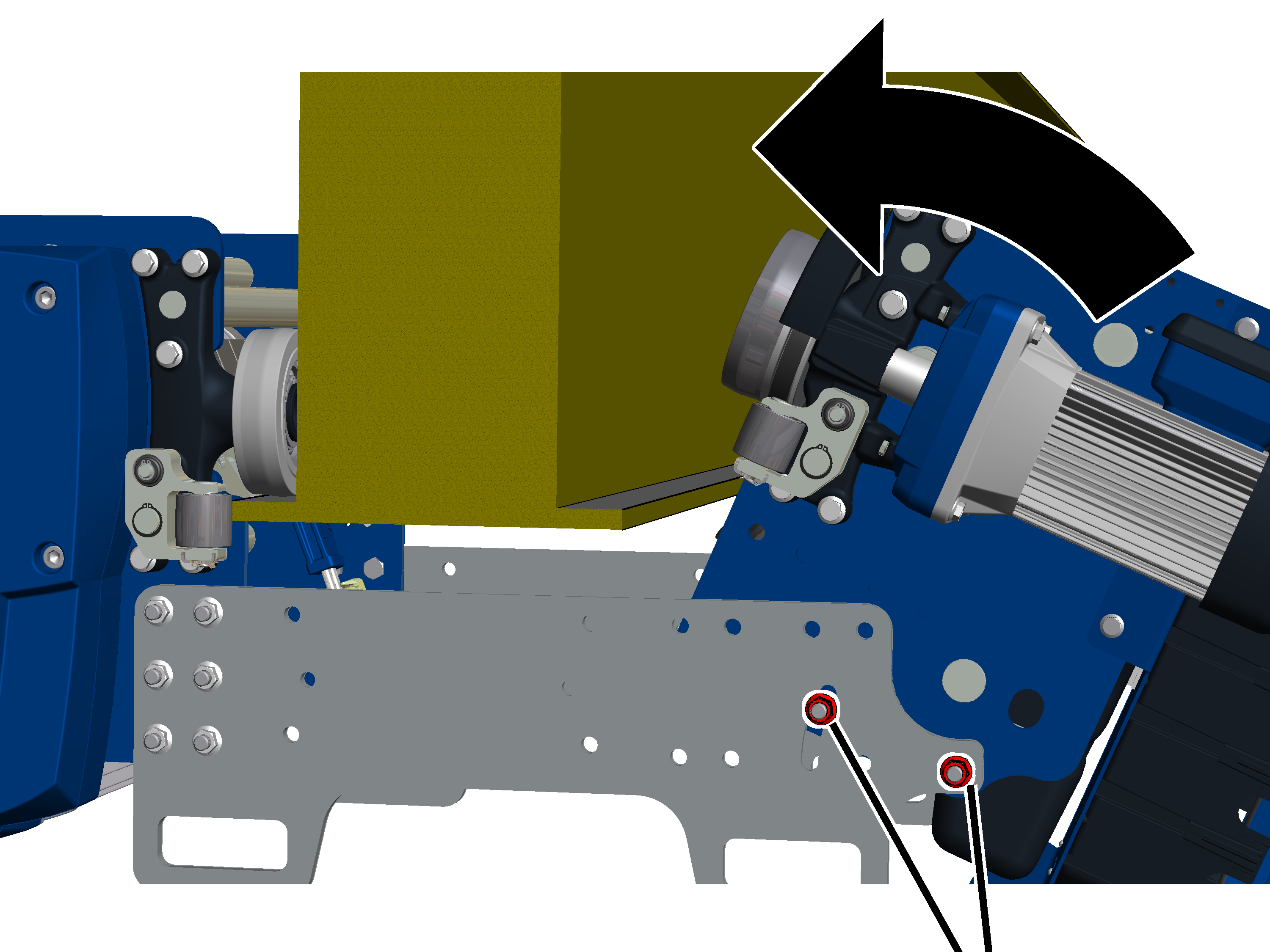
Now the wire rope hoist is tipped back.
|
| |
|
|
Slightly loosen hexagon head screw in slot and pivot. |
Slightly loosen rib nuts in
pivot and slot.
|
|
Do not damage guide rollers! The guide rollers can be damaged when the guide rollers of the wire rope hoist hit against the main girder. Position the wire rope hoist precisely and move it carefully. |
Carefully tip back the
counterweight side and place the wheels on the lower flange or bottom
flange.
Now the flange plates are screwed tight on both sides.
On both flange plates:
|
Rib nut M12 |
|
|
| |
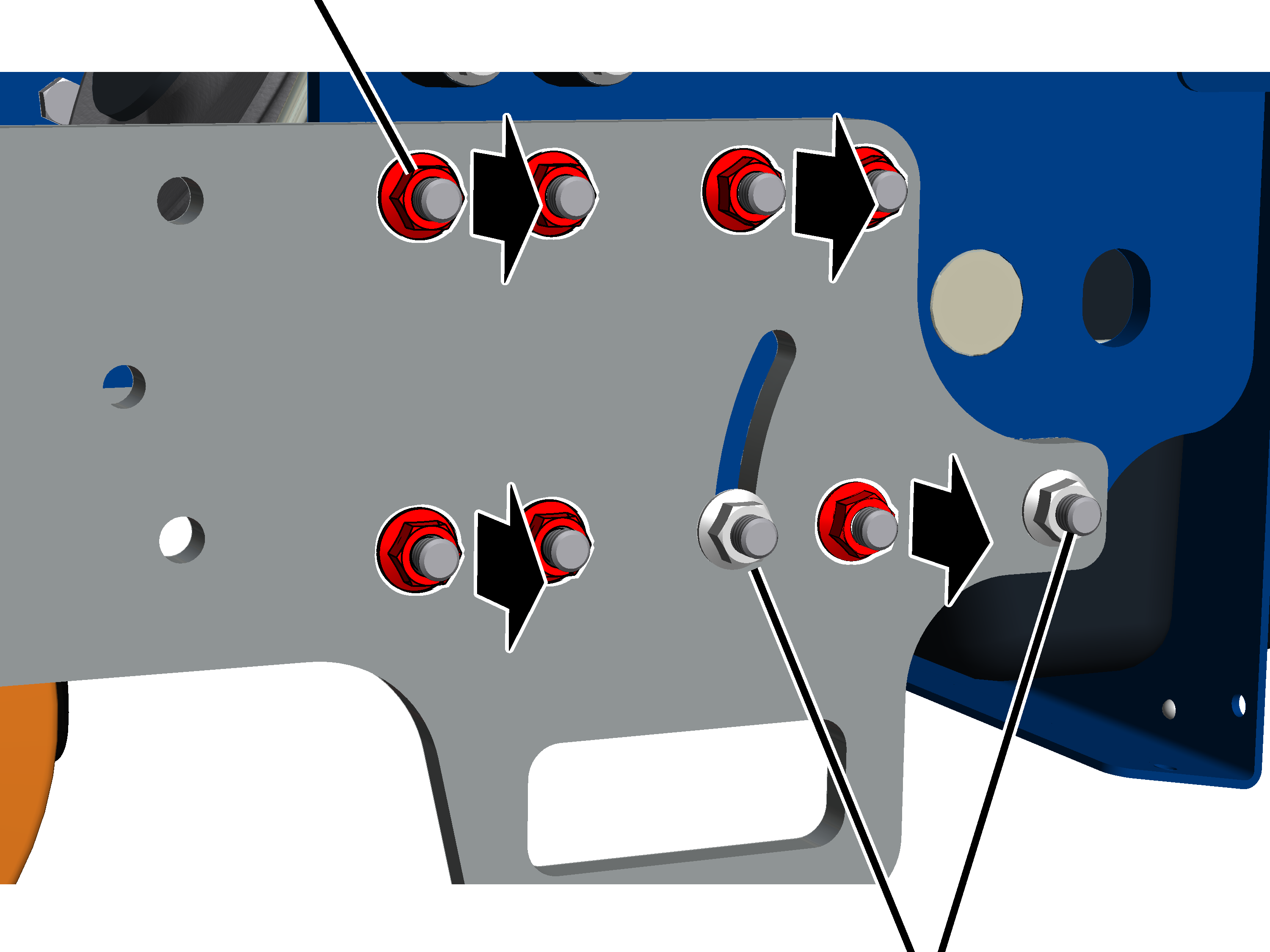
Push M12x40 hexagon head screws
(shown in red) through the trolley frame and the flange plate.
|
Size |
Screws on the counterweight side for each flange plate |
Screws on the drum side for each flange plate |
|
GM 800 |
4x 2x in the pivot and slot |
4x |
|
GM 1000 |
7x 2x in the pivot and slot |
6x |
Screw on M12 rib nut (shown in
red) from the outside. 85 Nm.
Now the guide rollers have to be set.
See Adjusting the guide rollers.