If available: Read the position
of the mains power carrying fork from the planning documents (drawing
“Installation position of mains power carrying fork (MCF)”).
If available: Read the position
of the mains power carrying fork from the planning documents (drawing
“Installation position of mains power carrying fork (MCF)”).
Depending on the type of crane and the on-site conditions in the building, the mains power supply is installed differently.
If available: Read the position
of the mains power carrying fork from the planning documents (drawing
“Installation position of mains power carrying fork (MCF)”).
Additionally: Select the
installation version required at the site from the following versions and the
scope of delivery.
Installation versions for panel on the end carriage:
|
Possible second mount |
Mount |
|
| |
|
Vertical square tube |
Possible second vertical square tube |
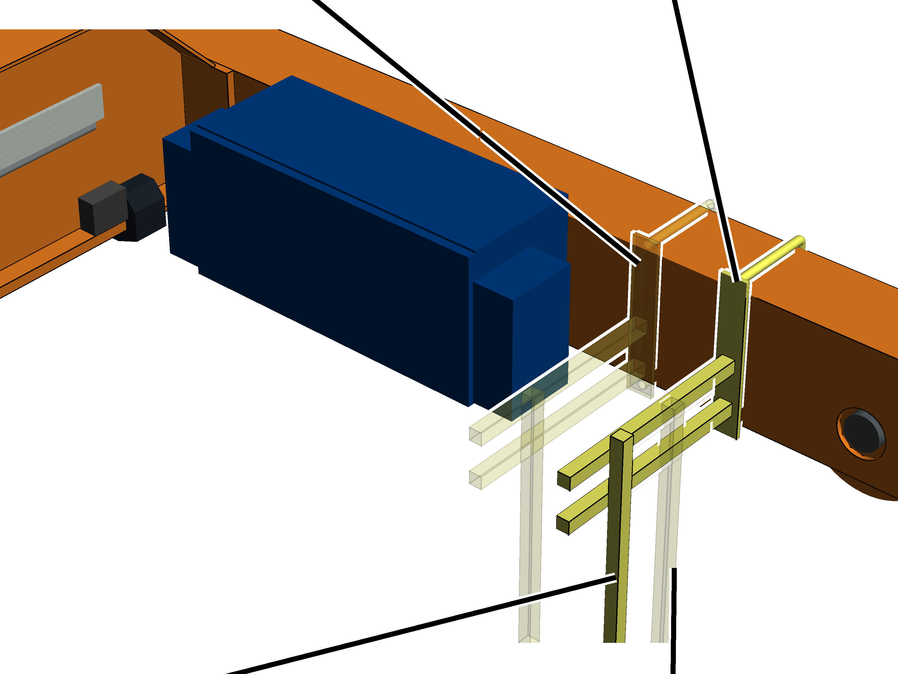
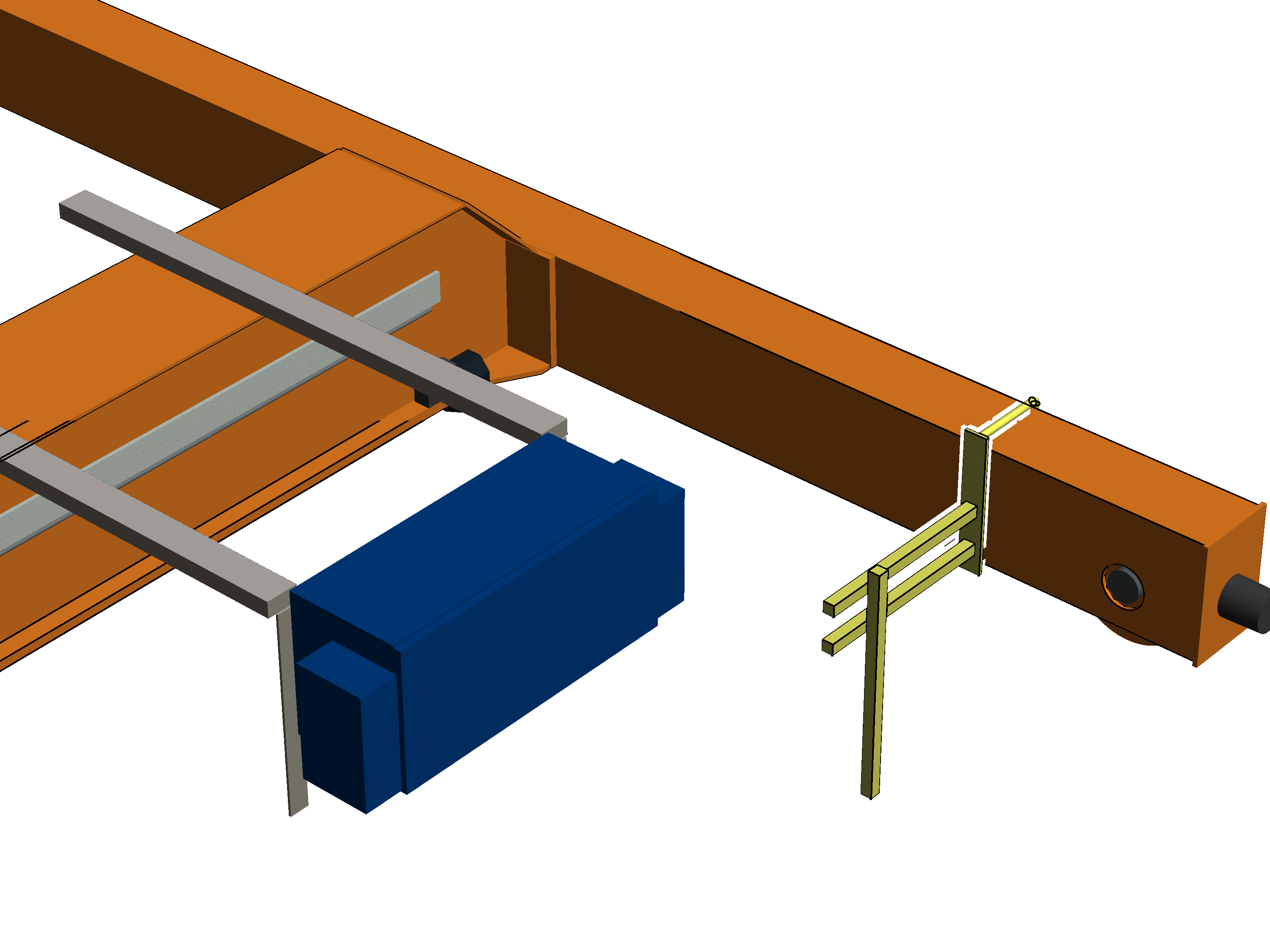
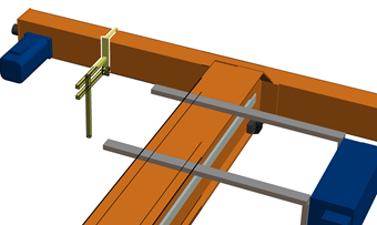
Preferred version: mains power carrying fork on the end carriage next to the panel
─ This preferred version can be used if there is adequate space between the outer edge of the panel and the opening for the wheel.
|
Cable entry housing |
Area for assembly of the mounts |
|
| |
|
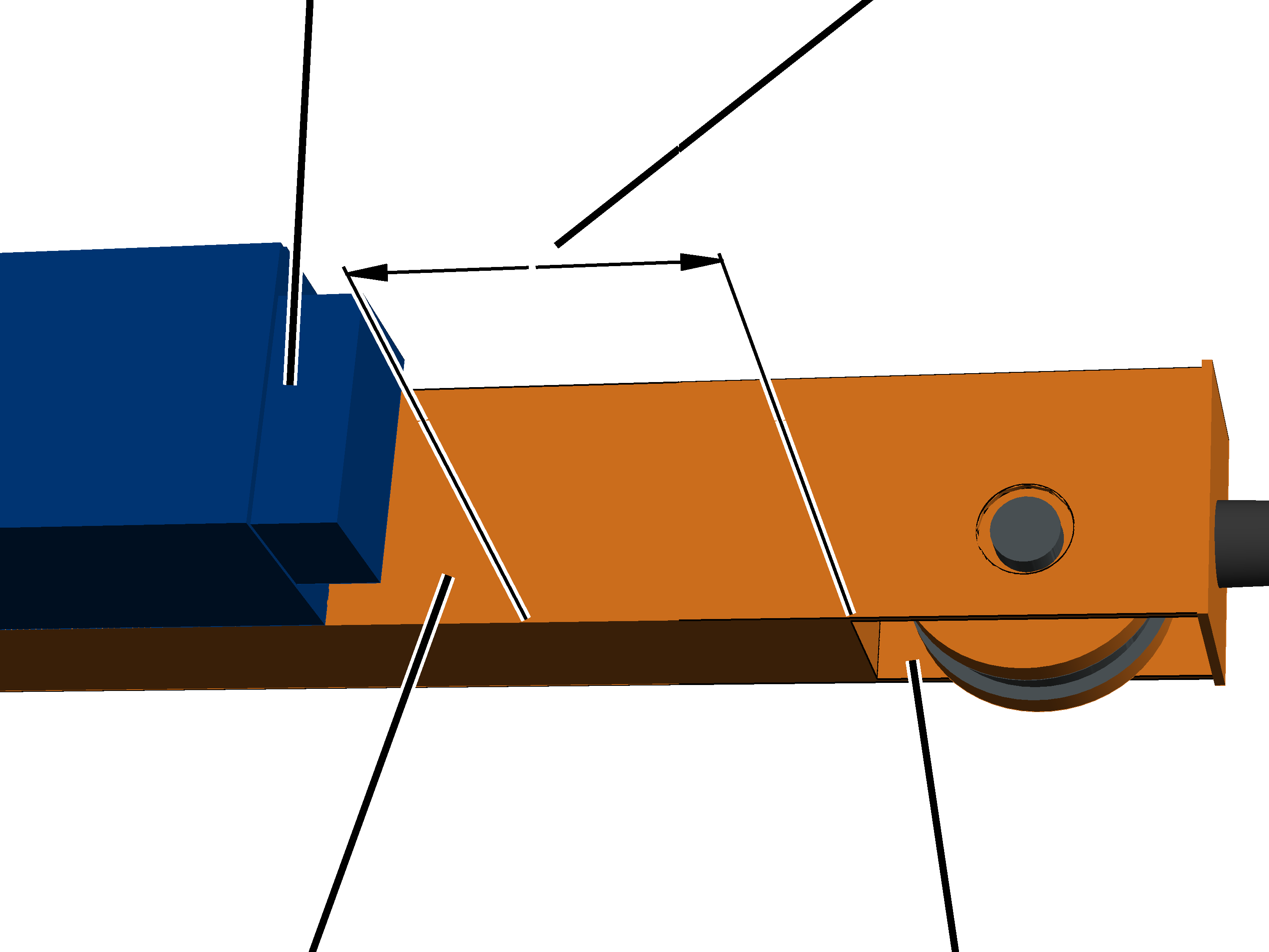
Free space for opening the cable entry housing |
Opening of the wheel |
It should be noted that to open the cover of the cable entry housing, approximately 10 cm free space is required at the side next to the panel.
It must be additionally considered that the mount may not be installed in the area of the wheel opening.
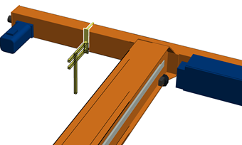
─ This preferred version can be used if the mains power carrying fork consists of a single mount.
If the mains power carrying fork has two mounts, there is in most cases insufficient space to install both mounts (see above). In this case, choose one of the following versions instead. However, if there is enough space available, installing the mains power carrying fork at this position is preferred.
─ For one mount: If the vertical square tube is 80 cm long, a single square tube is used.
For one mount: If the vertical square tube is 100 cm or 130 cm long, two square tubes are used.
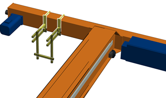
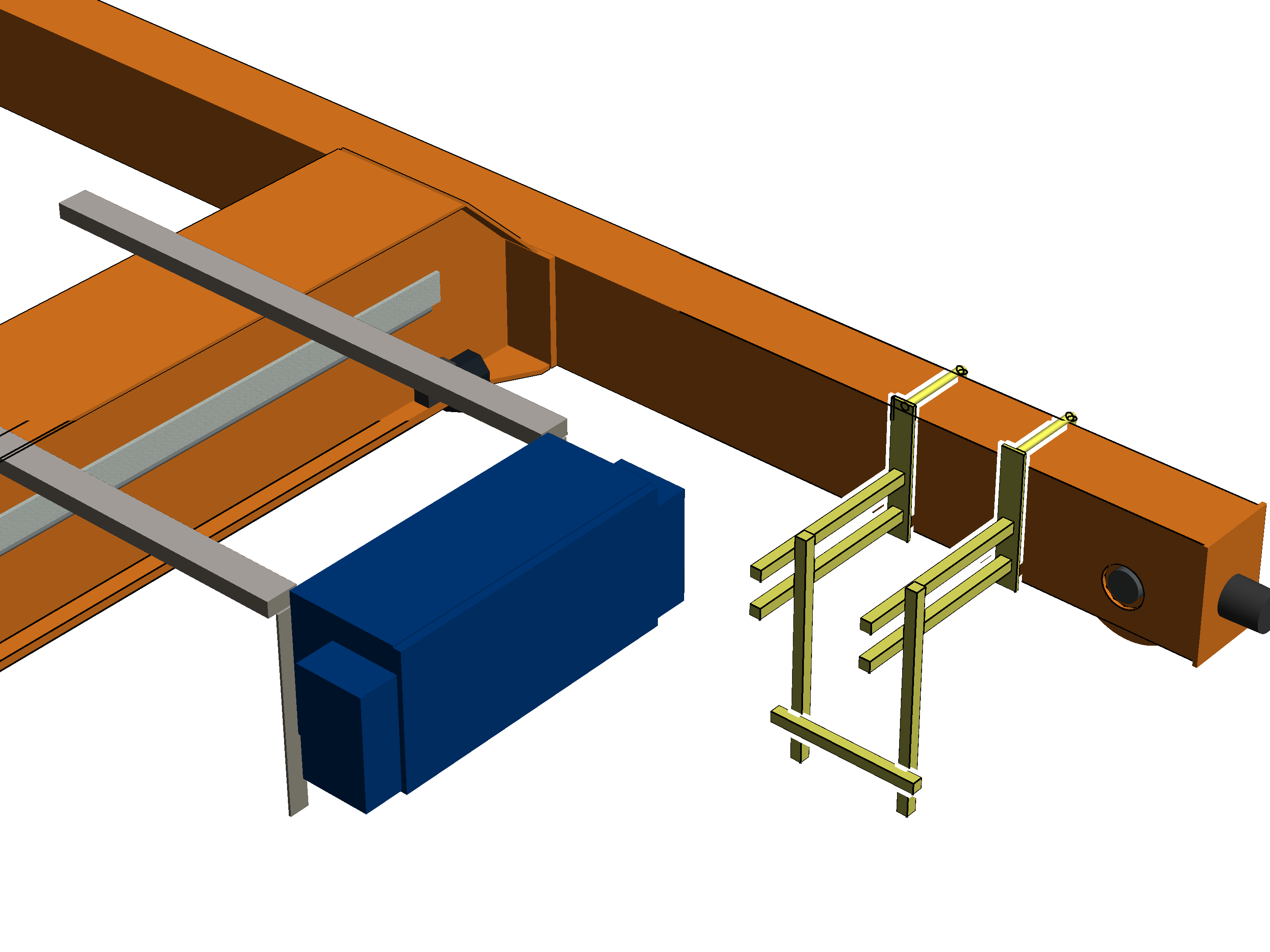
For two mounts: If the vertical square tube is 80 cm long, a single square tube is used on each mount.
For two mounts: If the vertical square tube is 100 cm or 130 cm long, two square tubes are used on each mount.
With 130 cm long vertical square tubes, the vertical square tubes of both mounts are additionally connected with each other crosswise by means of a square tube.
|
|
Next possible version: mains power carrying fork on the other side of the panel on the end carriage
─ This version can be used if there is insufficient space on the right side of the end carriage next to the panel (previous version).
The mains power carrying fork consists of a single mount or two mounts (see next version).
Whether the mains power carrying fork consists of one or two mounts is determined by the scope of delivery.
─ The mains power carrying fork must be installed inside as far as possible but still pose no risk of colliding with the trolley.
─ If the connection cable of the current collector is not long enough, an additional terminal box must be installed and the connection cable extended.
─ If the vertical square tube is 80 cm long, a single square tube is used.
If the vertical square tube is 100 cm or 130 cm long, two square tubes are used.
|
|
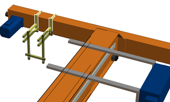
Next possible version: mains power carrying fork with dual mount on the other side of the panel on the end carriage
─ This version can be used if the mains power carrying fork consists of two mounts and the preferred version (see beginning) cannot be used.
Whether the mains power carrying fork consists of one or two mounts is determined by the scope of delivery.
─ The mains power carrying fork must be installed inside as far as possible but still pose no risk of colliding with the trolley.
─ If the connection cable of the current collector is not long enough, an additional terminal box must be installed and the connection cable extended.
─ If the vertical square tube is 80 cm long, a single square tube is used on each mount.
If the vertical square tube is 100 cm or 130 cm long, two square tubes are used on each mount.
With 130 cm long vertical square tubes, the vertical square tubes of both mounts are additionally connected with each other crosswise by means of a square tube.
Installation versions for a suspended panel:
|
B |
Preferred version: mains power carrying fork on the end carriage next to the panel
─ This preferred version can be used in most cases.
─ The mains power carrying fork consists of a single mount.
Whether the mains power carrying fork consists of one or two mounts is determined by the scope of delivery.
─ If the vertical square tube is 80 cm long, a single square tube is used.
If the vertical square tube is 100 cm or 130 cm long, two square tubes are used.
─ The mains power carrying fork must be installed inside as far as possible but still pose no risk of colliding with the trolley.
|
|
Next possible version: mains power carrying fork with dual mount on the end carriage
─ This preferred version can be used in most cases.
─ The mains power carrying fork consists of two mounts.
Whether the mains power carrying fork consists of one or two mounts is determined by the scope of delivery.
─ If the vertical square tube is 80 cm long, a single square tube is used on each mount.
If the vertical square tube is 100 cm or 130 cm long, two square tubes are used on each mount.
With 130 cm long vertical square tubes, the vertical square tubes of both mounts are additionally connected with each other crosswise by means of a square tube.
─ The mains power carrying fork must be installed inside as far as possible but still pose no risk of colliding with the trolley.
|
|
Next possible version: mains power carrying fork on the other side of the panel on the end carriage
─ This version can be used if there is insufficient space on the right side of the end carriage next to the panel (previous versions). Normally however, the clearance to the left and right next to the end carriage is identical on a crane with suspended panel.
─ The mains power carrying fork consists of a single mount.
Whether the mains power carrying fork consists of one or two mounts is determined by the scope of delivery.
─ The mains power carrying fork must be installed inside as far as possible but still pose no risk of colliding with the trolley.
─ If the connection cable of the current collector is not long enough, an additional terminal box must be installed and the connection cable extended.
─ If the vertical square tube is 80 cm long, a single square tube is used.
If the vertical square tube is 100 cm or 130 cm long, two square tubes are used.
|
|
Next possible version: mains power carrying fork with dual mount on the other side of the panel on the end carriage
─ This version can be used if there is insufficient space on the right side of the end carriage next to the panel (previous versions). Normally however, the clearance to the left and right next to the end carriage is identical on a crane with suspended panel.
─ The mains power carrying fork consists of two mounts. Whether the mains power carrying fork consists of one or two mounts is determined by the scope of delivery.
─ The mains power carrying fork must be installed inside as far as possible but still pose no risk of colliding with the trolley.
─ If the connection cable of the current collector is not long enough, an additional terminal box must be installed and the connection cable extended.
─ If the vertical square tube is 80 cm long, a single square tube is used on each mount.
If the vertical square tube is 100 cm or 130 cm long, two square tubes are used on each mount.
With 130 cm long vertical square tubes, the vertical square tubes of both mounts are additionally connected with each other crosswise by means of a square tube.
One or two mounts are now assembled on the left or right of the end carriage, according to the previously selected installation version.
If necessary:
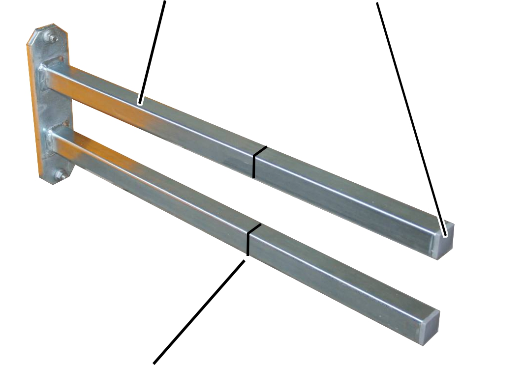
|
Mount |
Ribbed end cap |
|
| |
|
Shorten mount to required length |
|
Remove the ribbed end caps (2x)
from the mount.
Shorten the mount.
The required length is determined by the on-site conditions in the building and the safety clearances from the crane drawing.
Reinsert the ribbed end caps
(2x) into the ends of the mount.
|
| ||
|
| ||
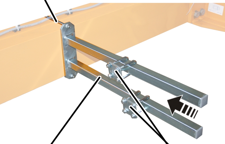
|
Mount |
Pipe clamp | |
Attach the mount to the end carriage on which
the crane panel is installed.
Bolt the mount onto the threaded bracket.
|
Threaded bracket |
Tightening torque |
|
M8 |
25 Nm |
|
M10 |
50 Nm |
|
M12 |
75 Nm |
Slide on the two pipe clamps and
secure them.
If necessary:
Remove the ribbed end cap from
the square tube.
Shorten the square tube.
Reinsert the ribbed end cap into
the square tube.
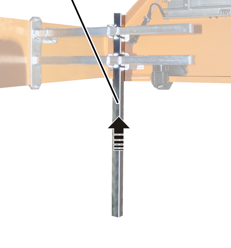
|
Vertical square tube |
|
|
| |
Move the vertical square tube to the required
position on the mount.
The required length is determined by the on-site conditions in the building and the safety clearances from the crane drawing.
Screw the vertical square tube
onto the mount using pipe clamps (2x). Tighten to 15 Nm.
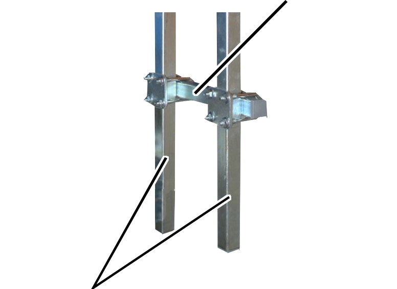
For more than one vertical square tube:
|
|
Horizontal square tube |
|
| |
|
Vertical square tube |
|
Attach the horizontal square tube with two pipe
clamps to the vertical square tubes.
The horizontal square tube can be a single square tube or a part of the current collector on the mains power supply.
Tighten the pipe clamps (2x).
Tighten to 15 Nm
The required components are now installed on the prepared mains power carrying fork.
─ Current collector of the mains power supply.
─ Cross-type limit switch. See Installing the cross-type limit switch.
─ Horn
─ Red signal lamp