Only with cross-type limit switch
This section is only applicable if the overhead travelling crane has a cross-type limit switch in the direction of crane travel.
Where and for which travel limit the cross-type limit switch is designed is specified on the wiring diagram.
|
|
Danger due to malfunction! If the cross-type limit switch is screwed on too tightly, the parts on the inside can become jammed and no longer function properly. The tightening torque of 3 Nm must be strictly observed. |

|
Threaded bracket | |
|
| |
|
Cross-type limit switch |
|
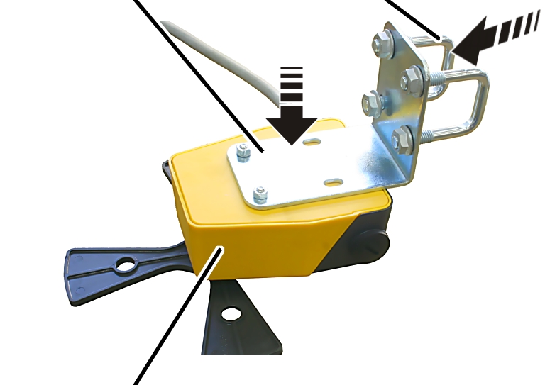
 Screw the mounting bracket onto
the cross-type limit switch with the fillister-head screws M5x50 (2x).
Screw the mounting bracket onto
the cross-type limit switch with the fillister-head screws M5x50 (2x).
Screw on the mounting bracket
using locking washers and M5 hex nuts (2x). 3 Nm.
Insert threaded brackets (2x) in
the mounting bracket.
Loosely screw in the M8 rib nuts
(4x).
Installing the cross-type limit switch on the mains power carrying fork
The cross-type limit switch can be installed on the mains power carrying fork, for example.
|
Crane travel limit switches |
|
|
| |
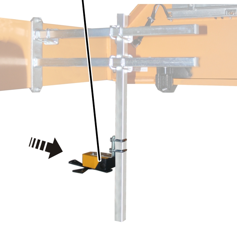
Turn the travel limit switch to
position 0.
The position of the cross-type limit switch is marked with an arrow that can be rotated further, depending on the switching state.
Hold the travel limit switch
against the square tube so that the switching lug activates the travel limit
switch.
Screw the travel limit switch
onto the vertical square tube using pipe clamps (2x). Tighten to 15 Nm
Connecting the cross-type limit switch
Route the connection cable
(round cable or flat cable) from the cross-type limit switch to the panel.
Route the connection cable with
cable fitting into the panel.
If necessary: Connect the
connection cable to a coupler plug or connector.
Fasten the connection cable with
cable ties, cable ducting and adhesive clips.
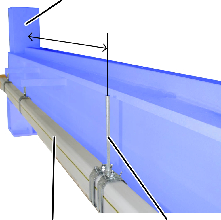
Attaching the actuating cam
|
End stopper |
|
|
| |
|
Conductor system |
Actuating cam |
Suspend a load on the load hook which
corresponds to the maximum load capacity of the crane.
Determine the necessary distance
between the actuating cam and the end stopper:
For braking function: The distance must be such that the crane is only travelling at a low speed shortly before the end stopper.
For shut-down: The distance must be such that the crane is at a standstill shortly before the end stopper.
Install the actuating cam for
the crane travel limit switch to the crane track or conductor system at the
determined distance.