If the deflection roller crosshead is damaged, it must be
replaced.
Disassembling
the deflection roller crosshead
Only with wire rope hoist
with hoist drive GM 7000 and reeving 4/1
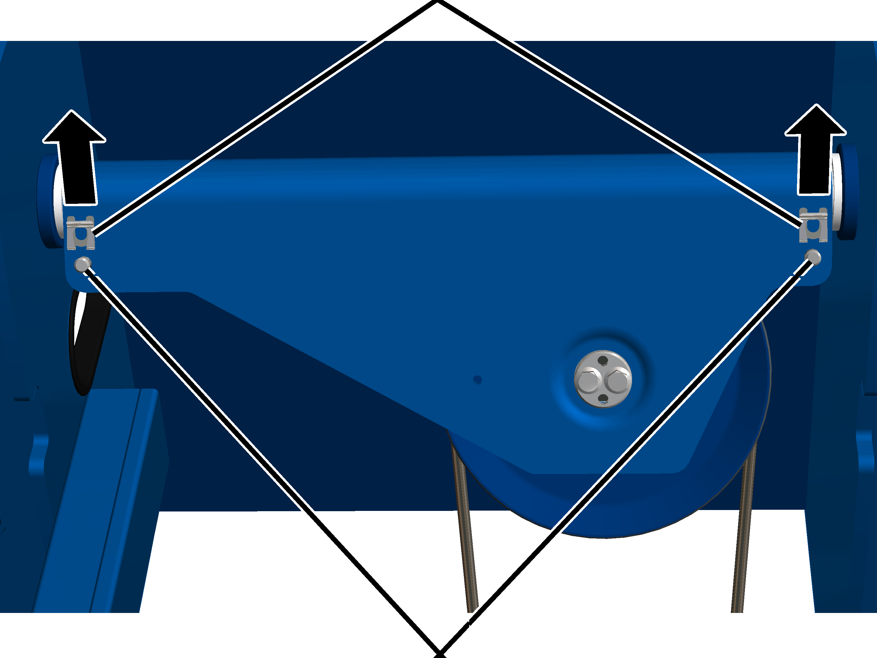
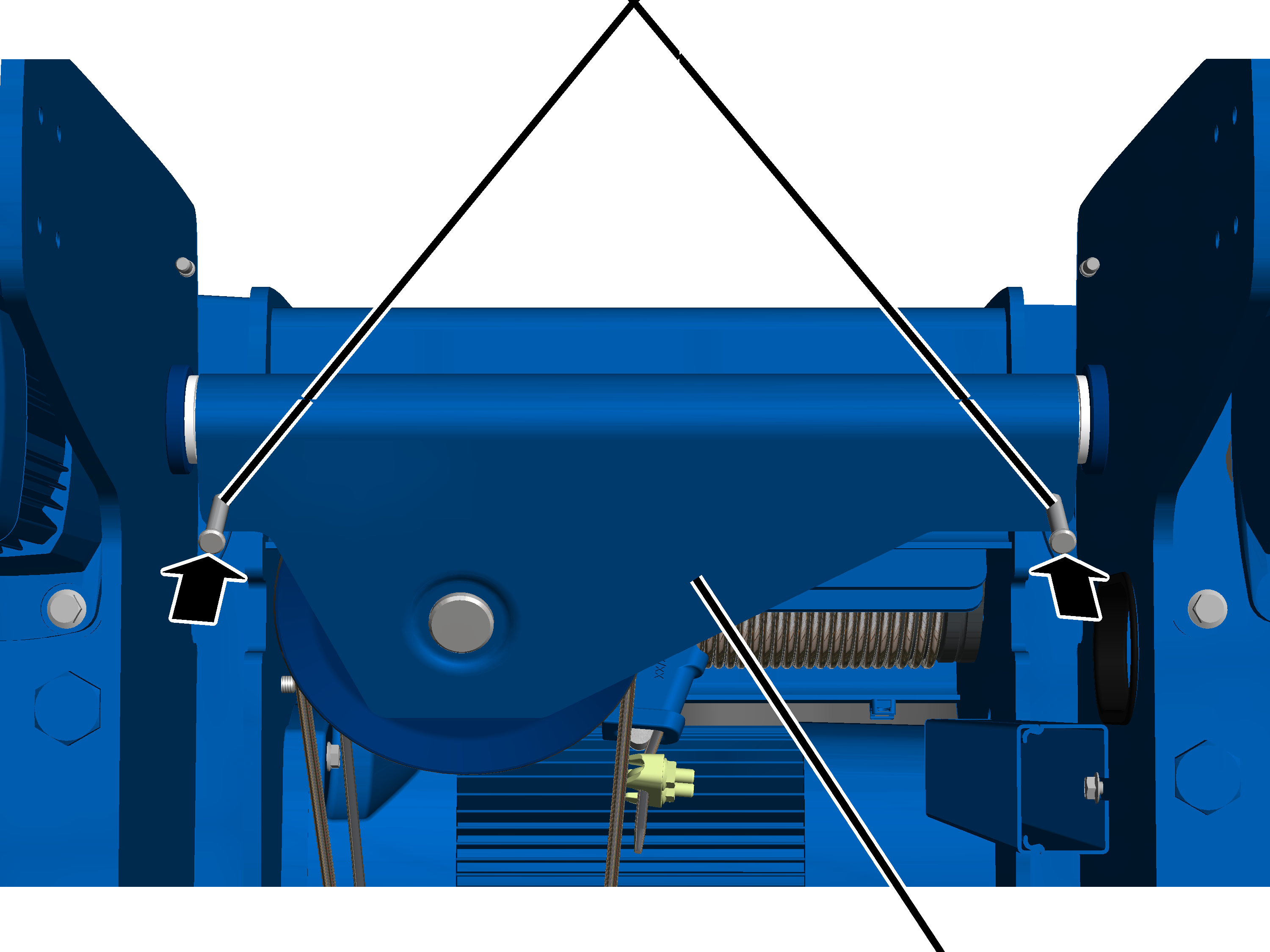
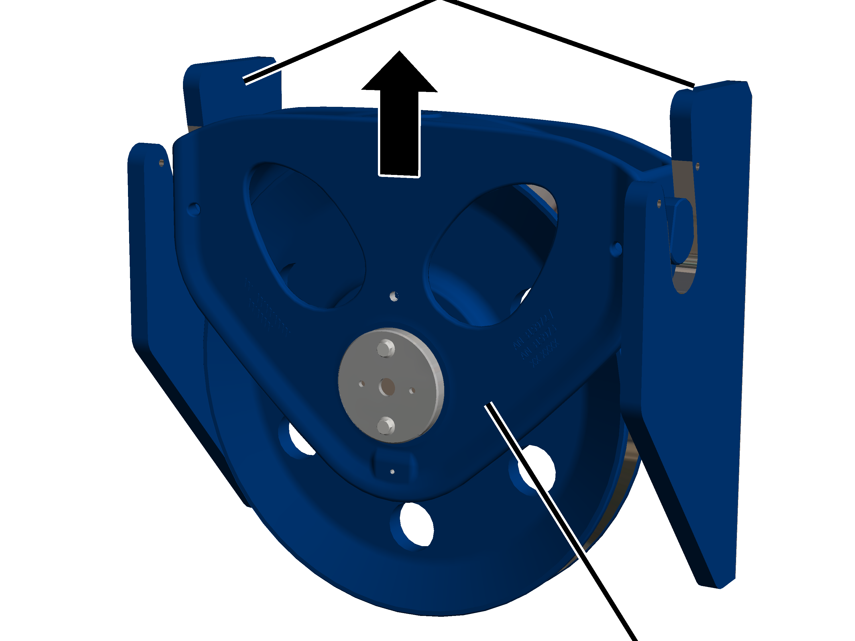
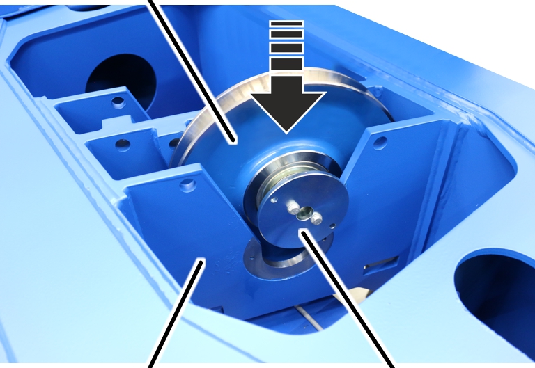
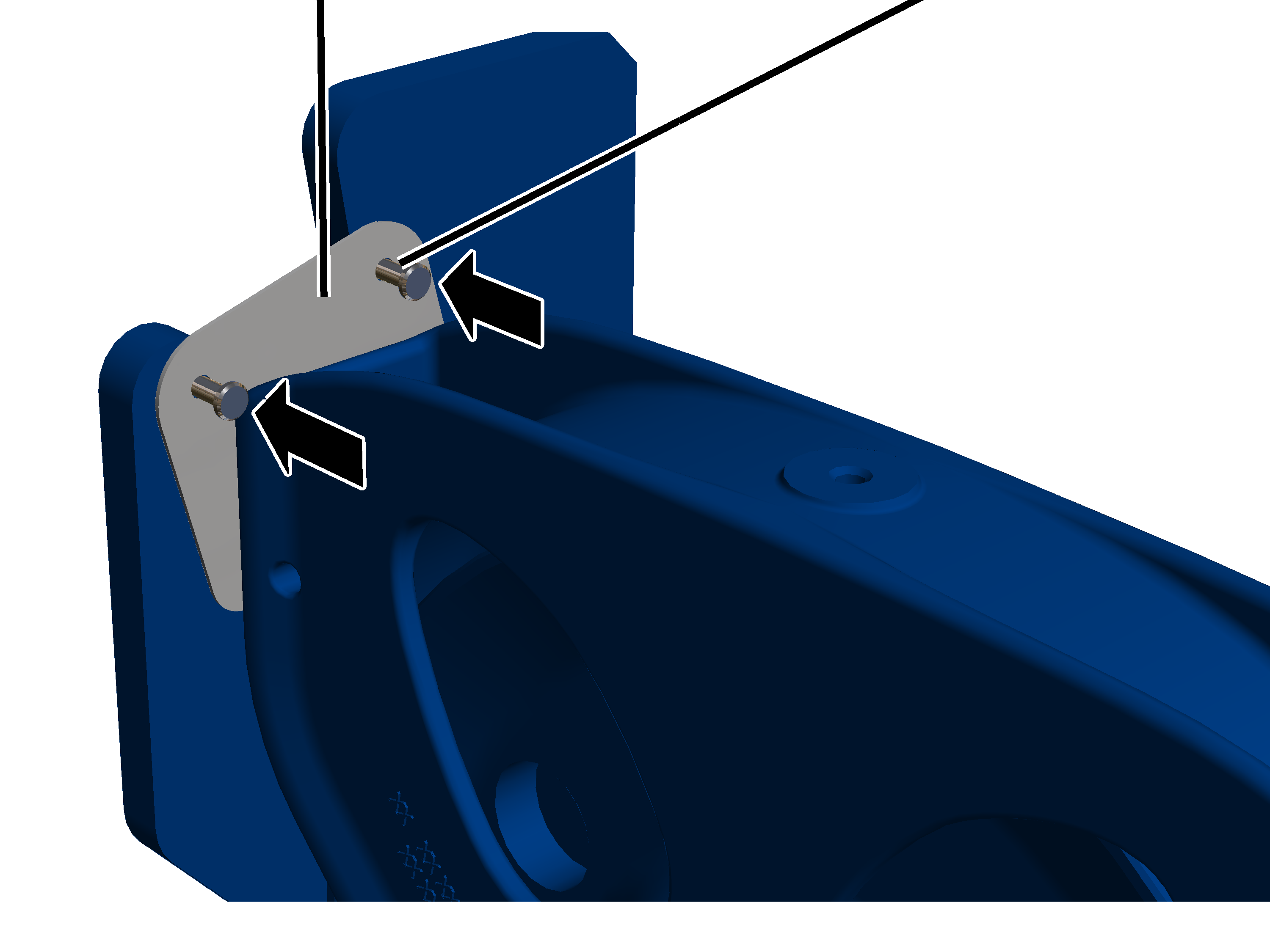
On a wire rope hoist with hoist drive GM 7000 and a
reeving 4/1, the deflection roller crosshead is installed on the outside of the
trolley frame.
On both sides:
|
SL
safety clip |
|
|
|
|
|
Bolt |
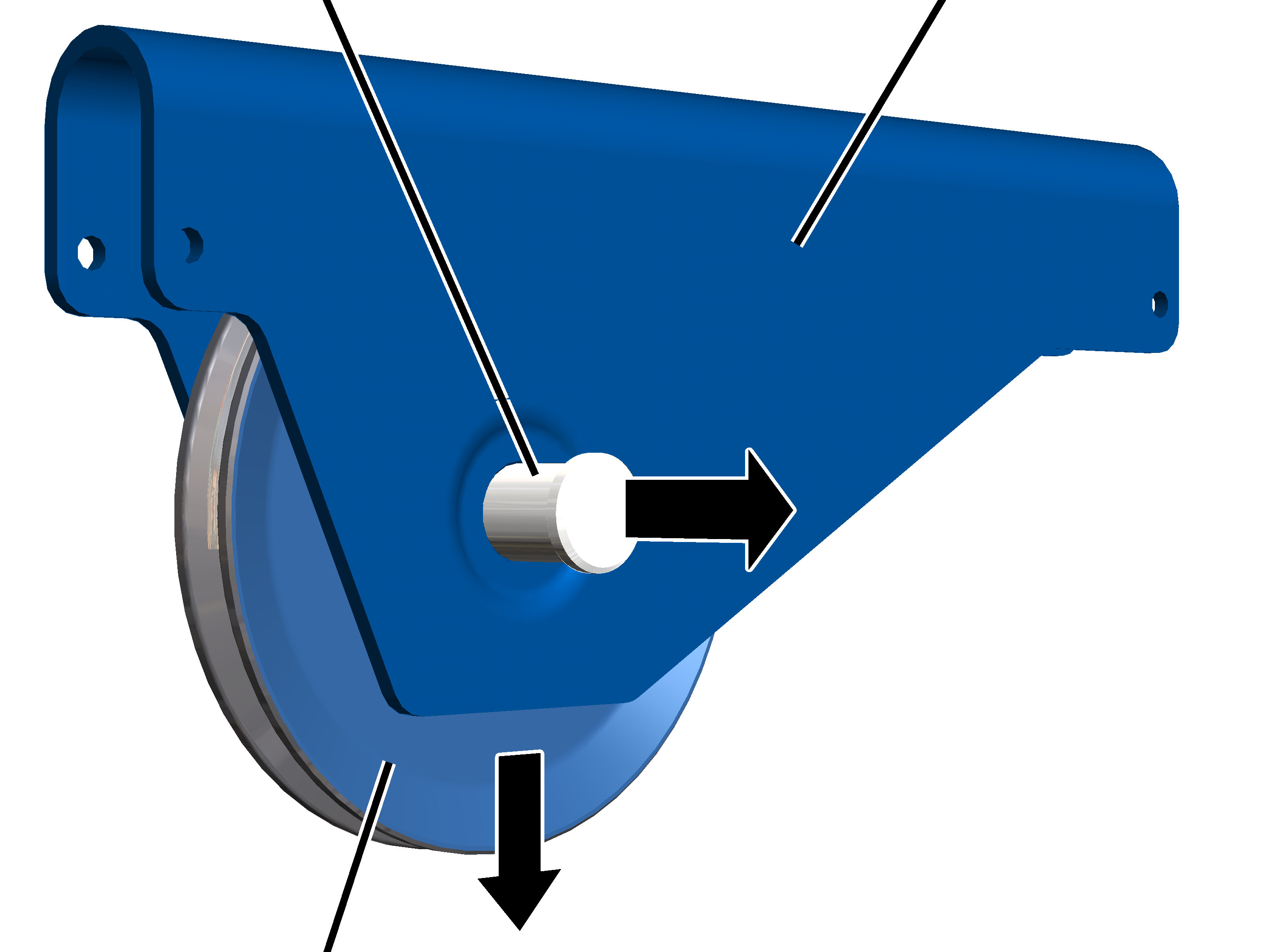
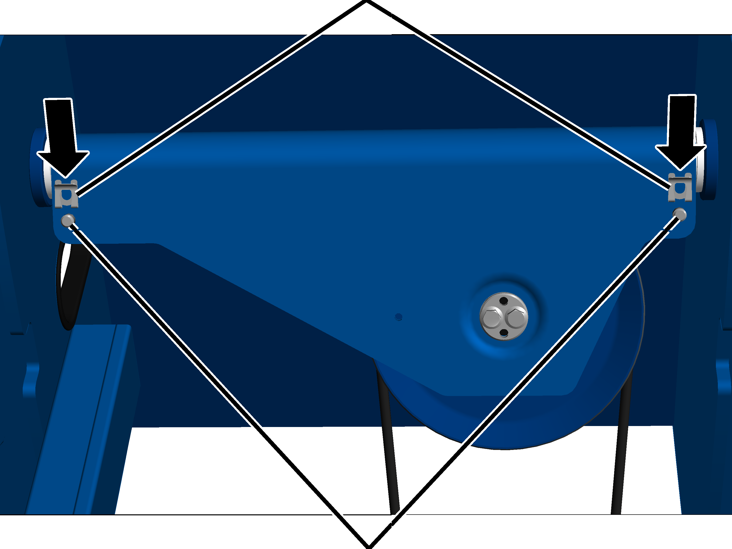
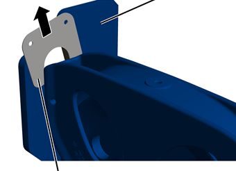
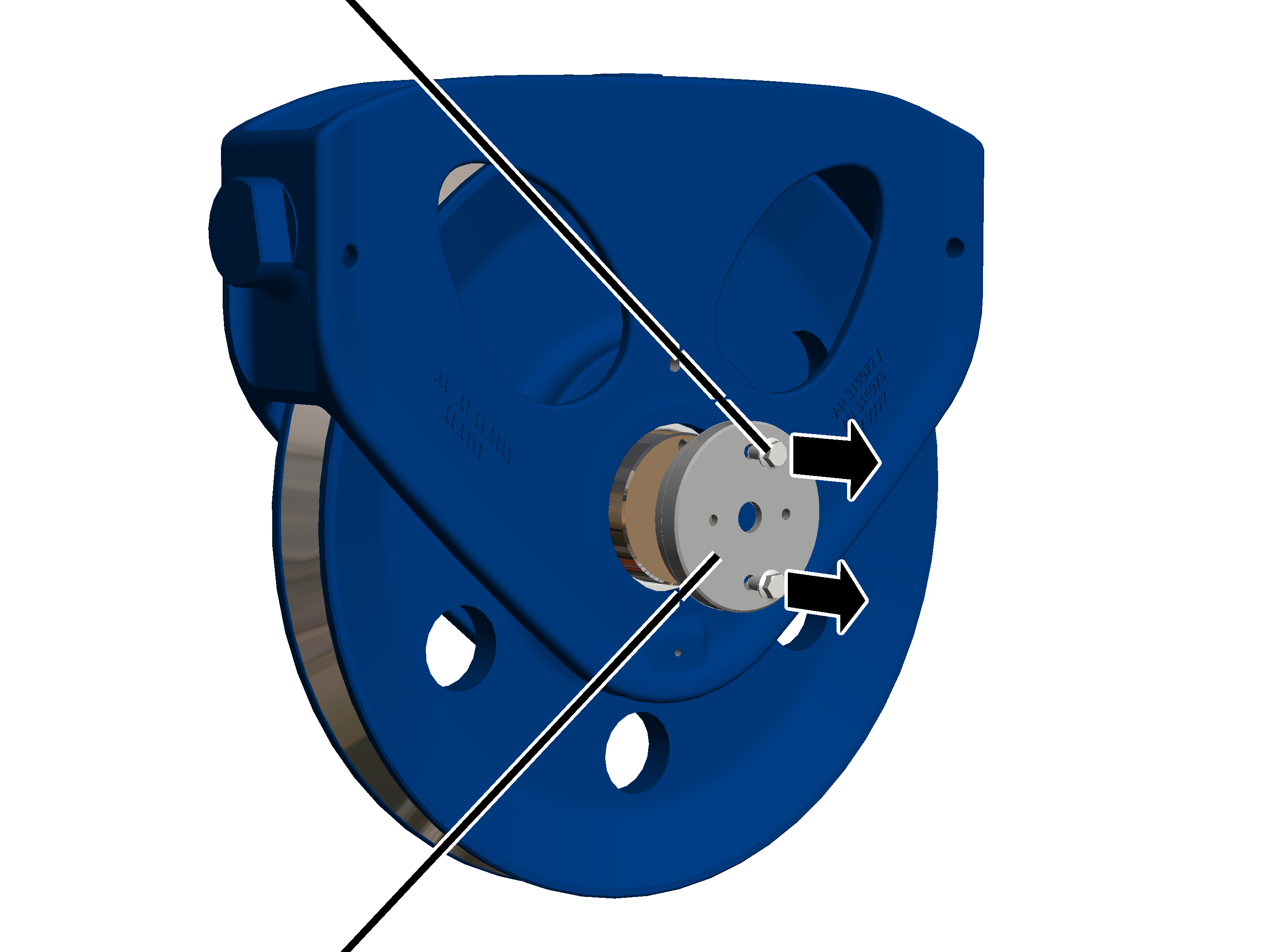
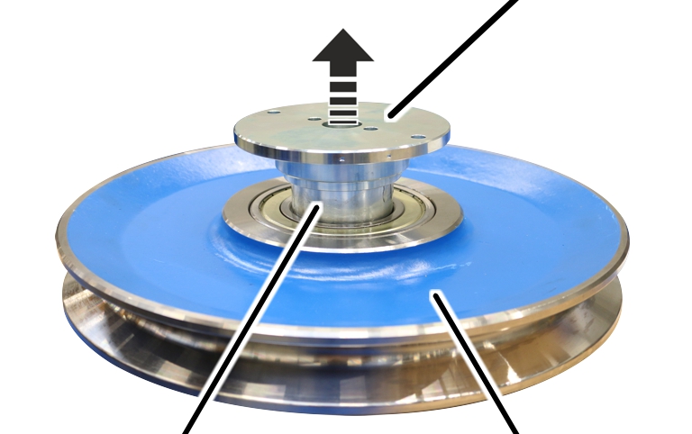
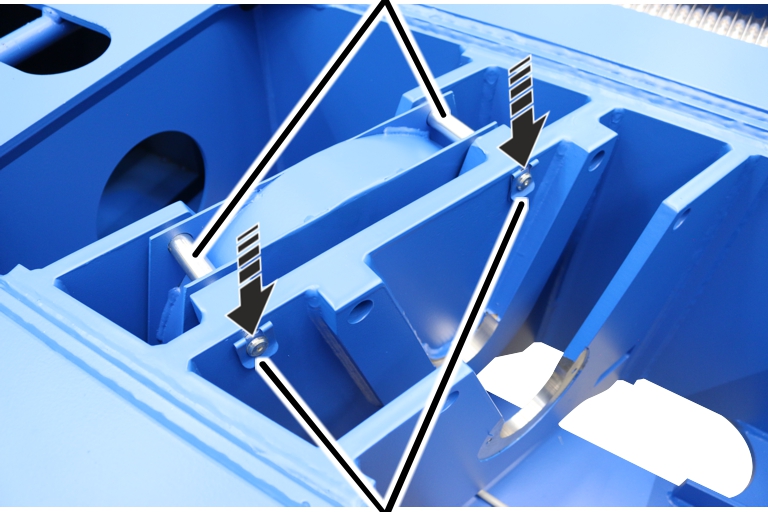
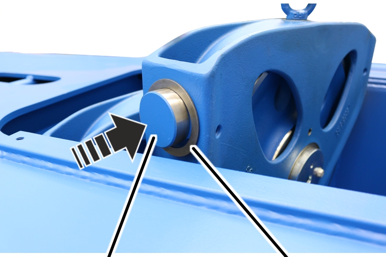
 Pull SL safety clip from the bolt.
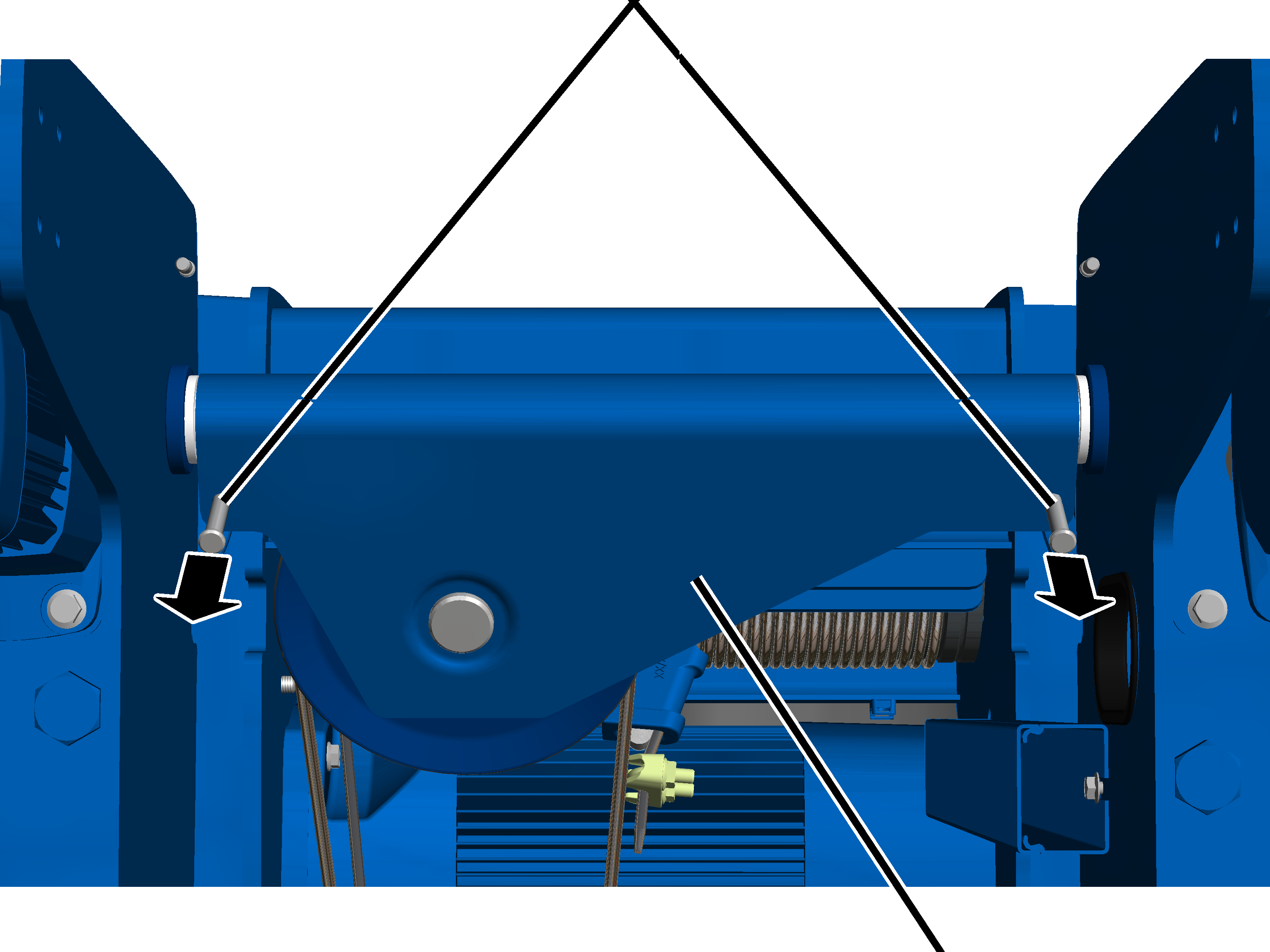
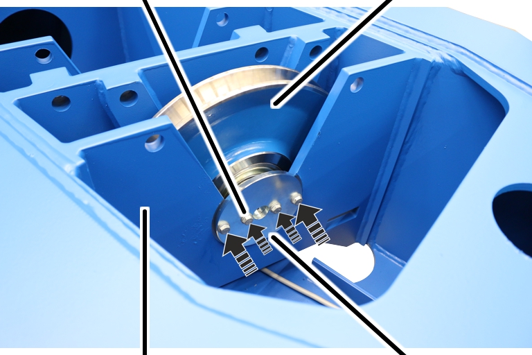
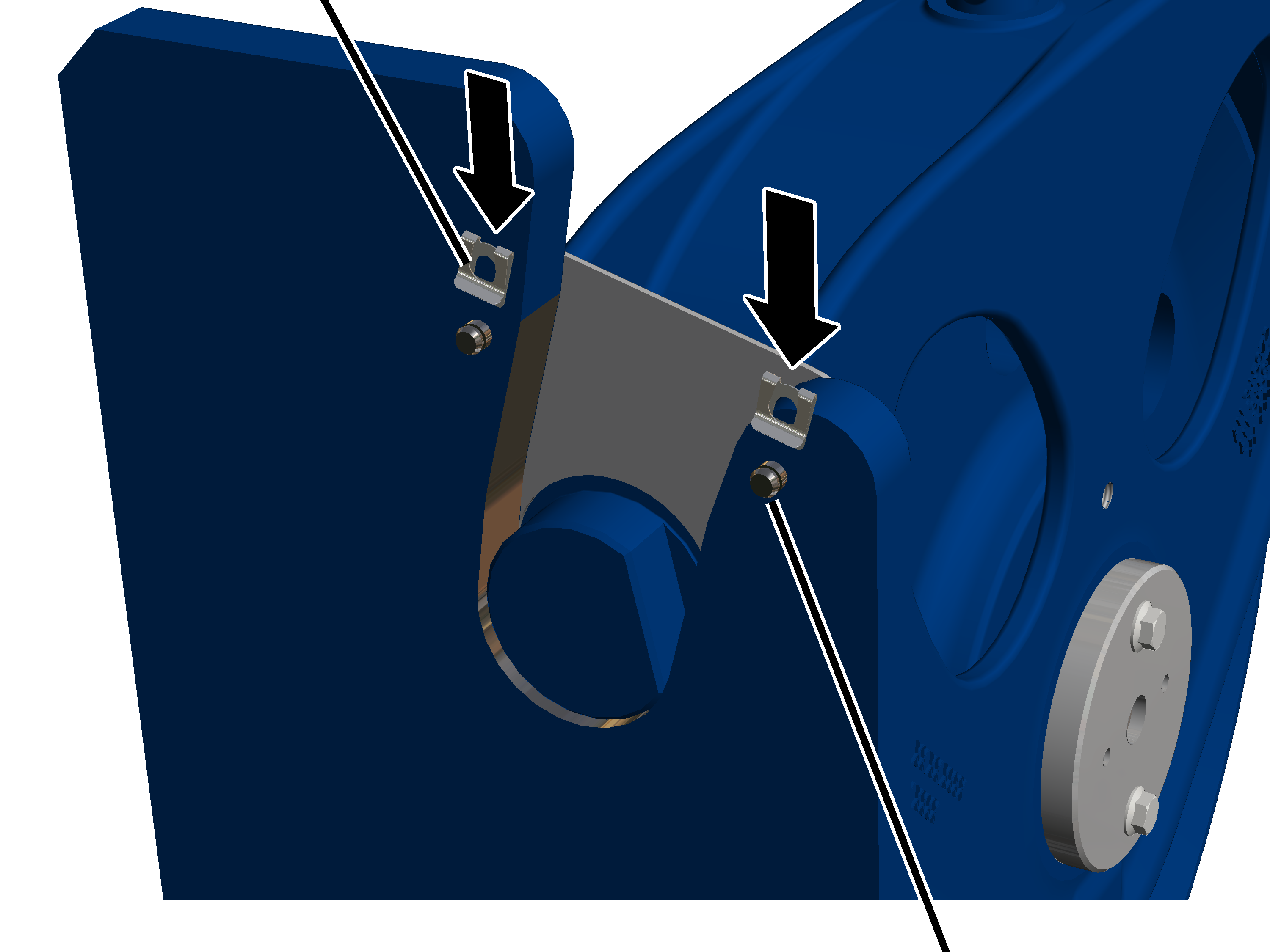
|
Safety
plate |
Bolt |
|

|
Pull the bolt out of the safety plate and the side panel.
|
|
Side
panel |
|
|
|
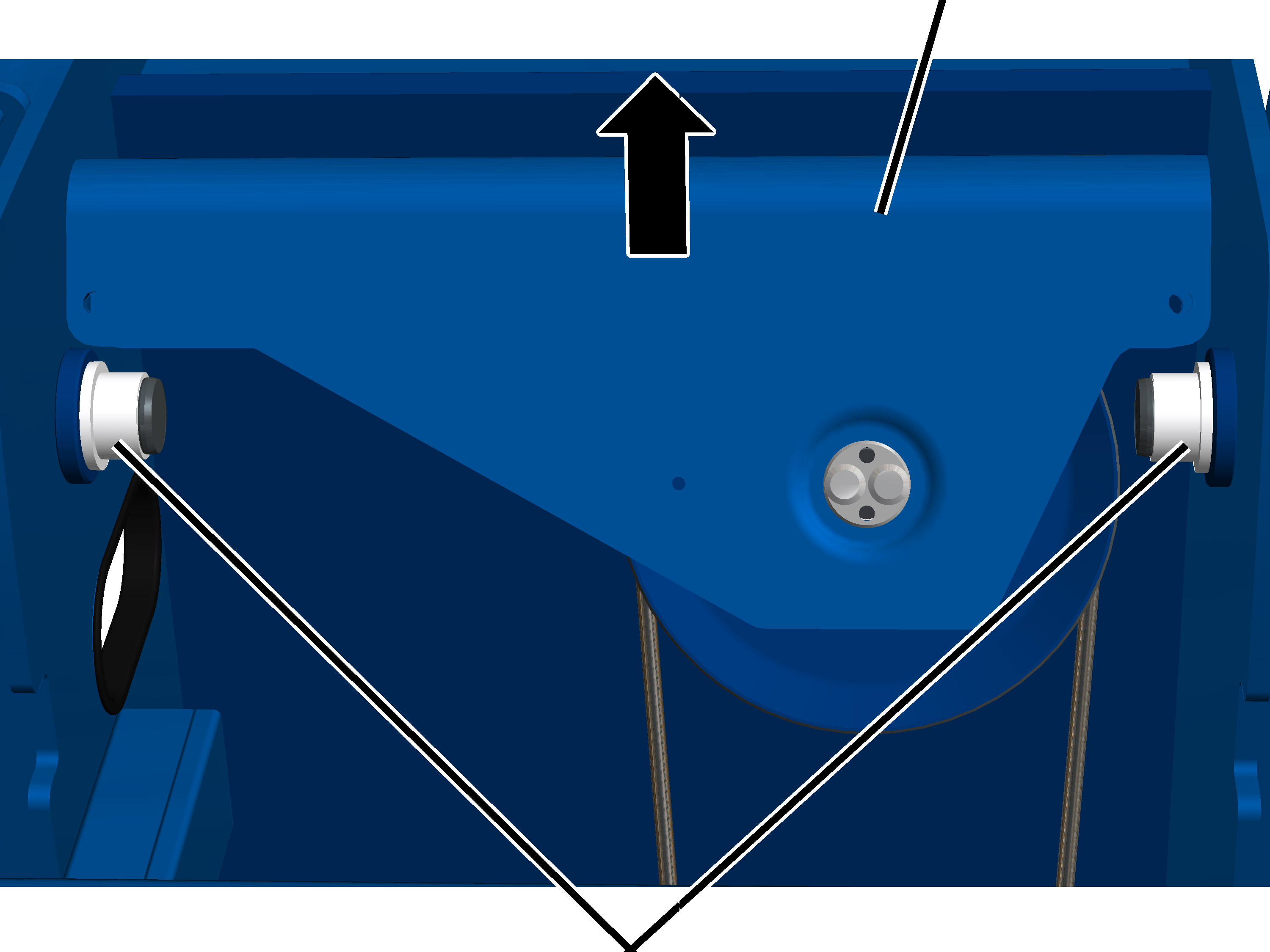
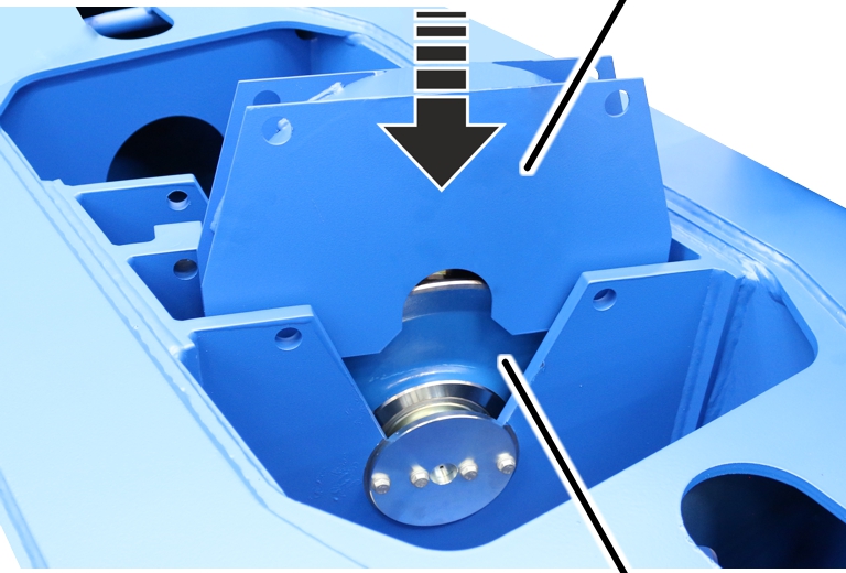
Safety
plate |
|
 Pull out the safety plate.
|
Side
panel |
|
|
|
|
Deflection roller crosshead |
Lift the deflection roller crosshead out of the side panels.
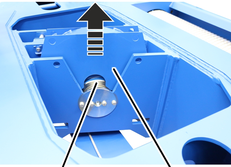
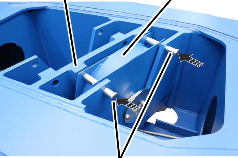
Only with wire rope hoist
with hoist drive GM 7000 and reeving 6/1
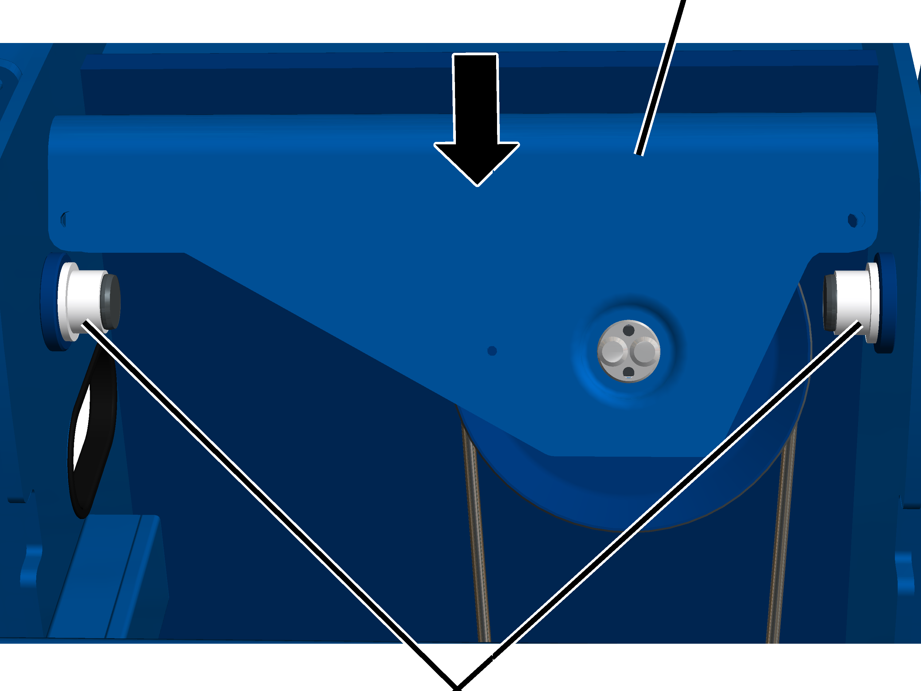
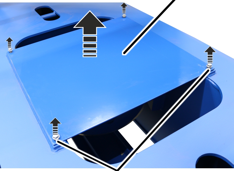
On a wire rope hoist with hoist drive GM 7000, the
deflection roller crossheads are installed in the trolley frame.
|
|
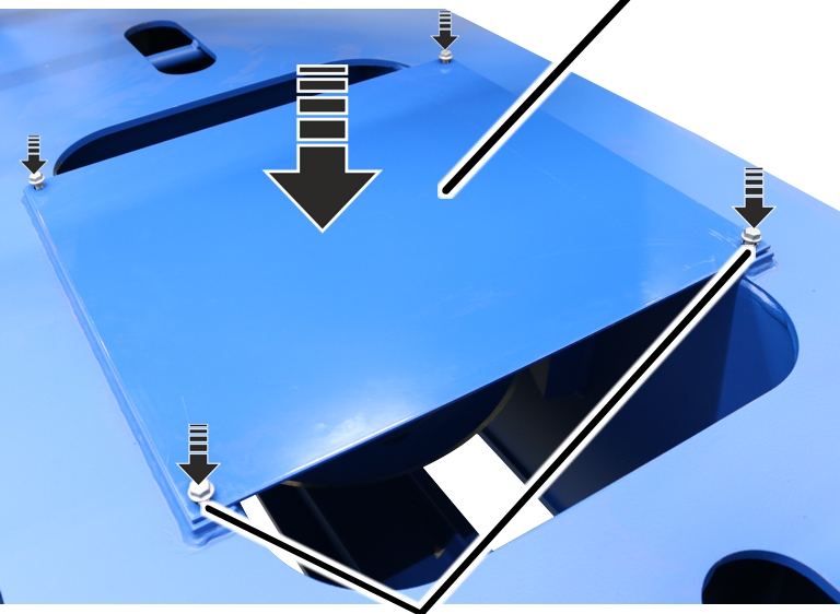
Metal
plate |
|
|
|
Rib
screws M10x16 |
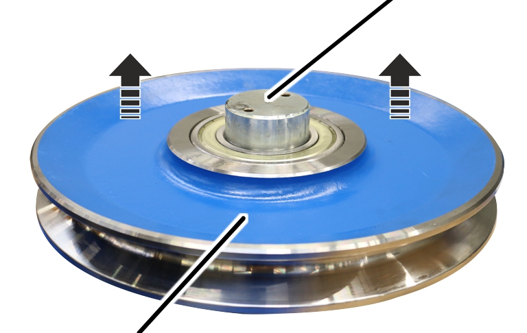
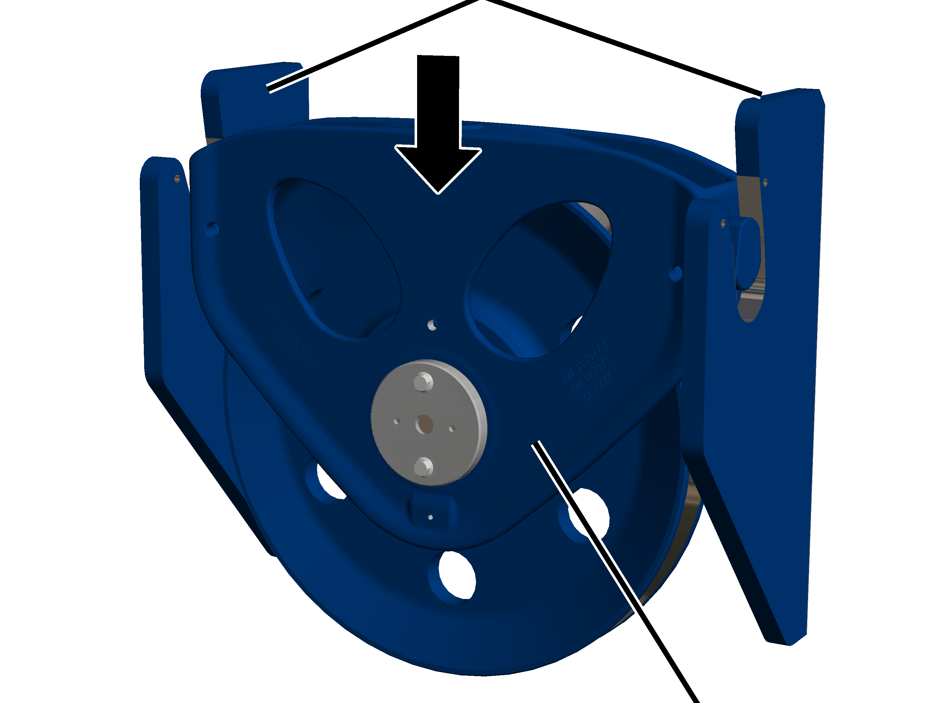
Release the rib screws M10x16 (4x) on the plate.
Lift the plate off the trolley frame.
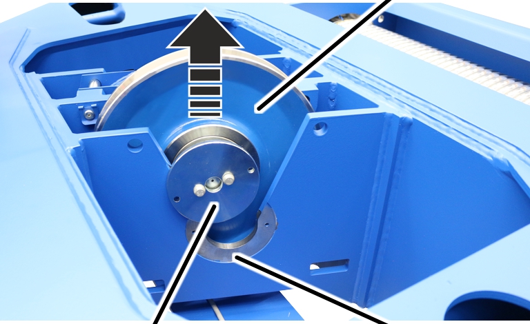
|
|
|
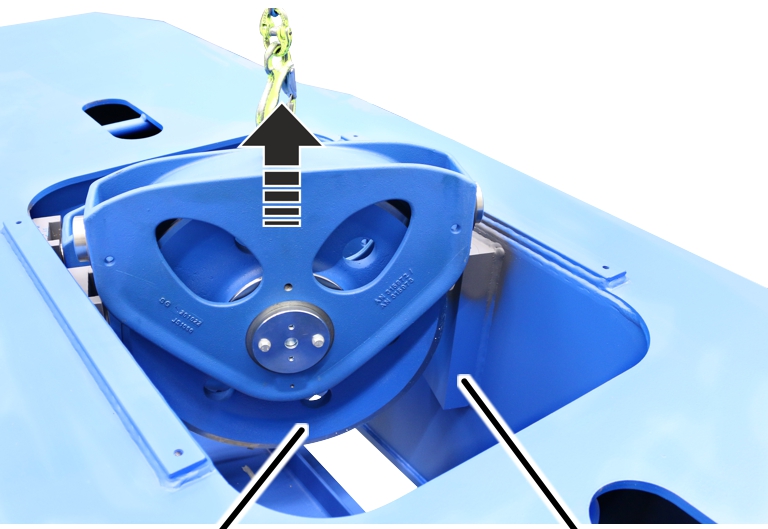
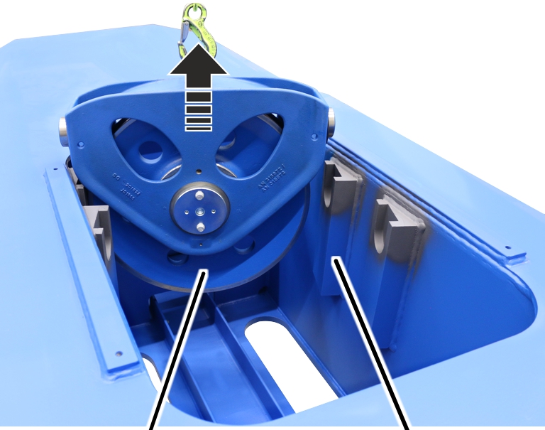
Deflection roller crosshead |
Suspension |
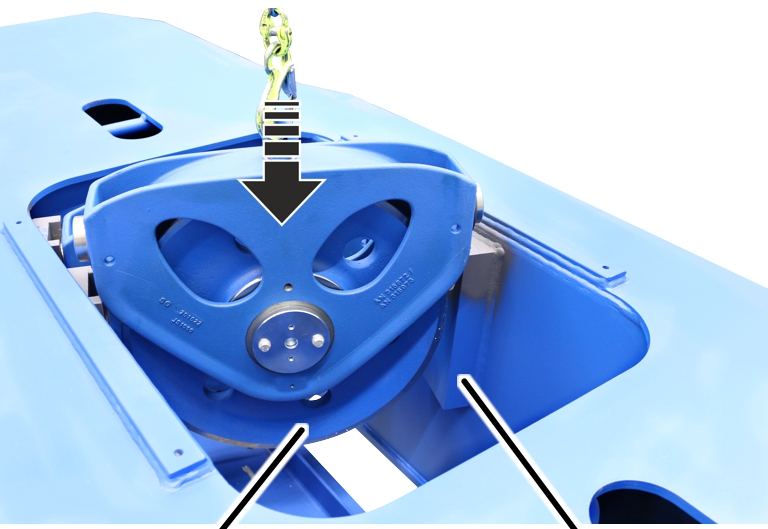
Lift the deflection roller crosshead out of the trolley frame.
|
|
|
Deflection roller crosshead |
Suspension |
Lift the second deflection roller crosshead out of the trolley
frame.
Disassembling
the deflection roller
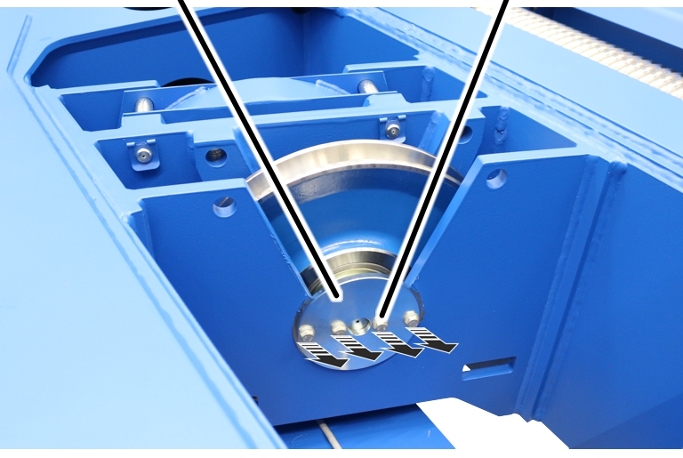
Only with wire rope hoist
with hoist drive GM 7000
On a wire rope hoist with hoist drive GM 7000, the
deflection roller is secured on the deflection roller using a bolt with a
cover.
|
Rib
screw |
|
|
|
|
Cover |
|
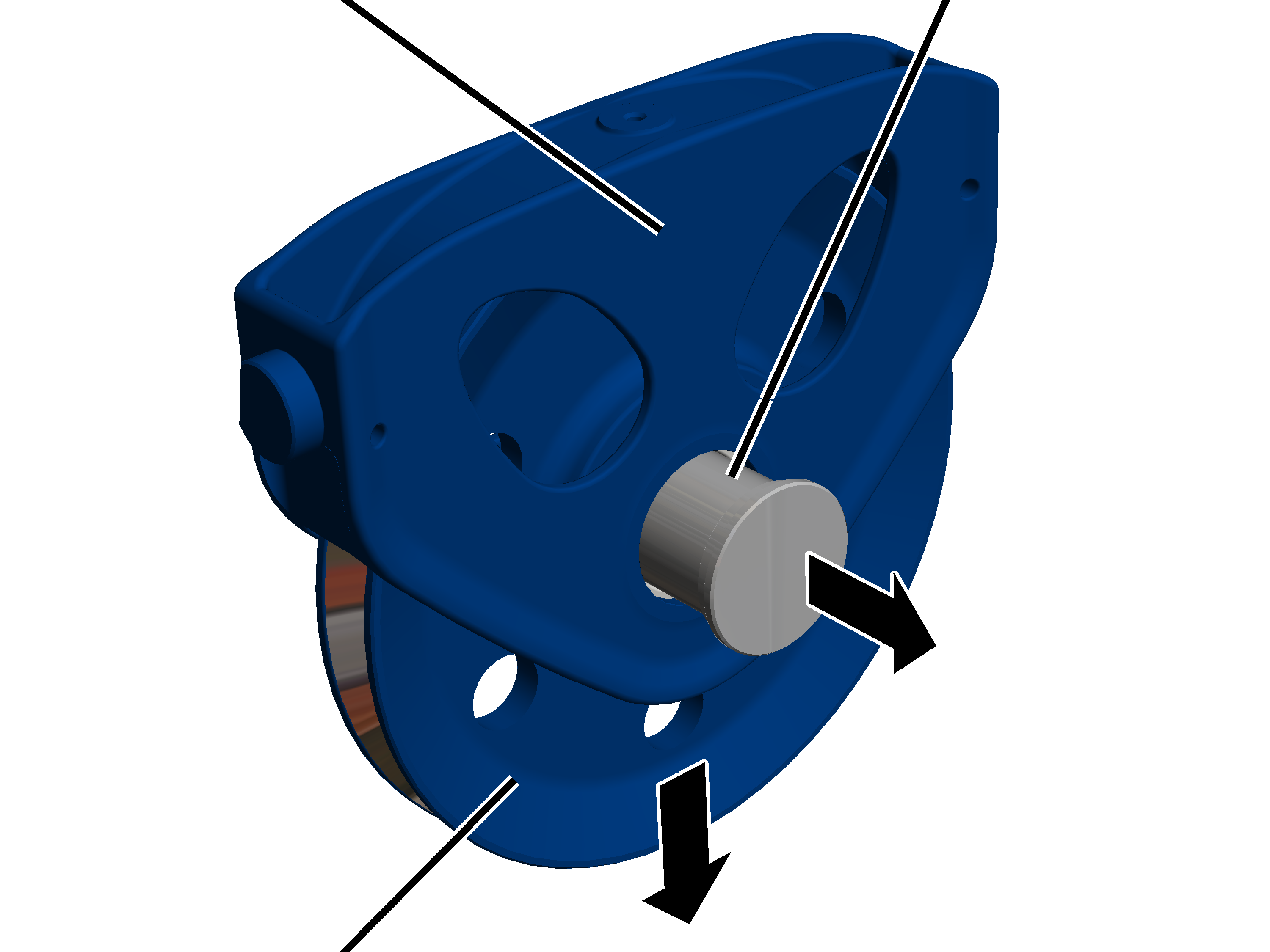
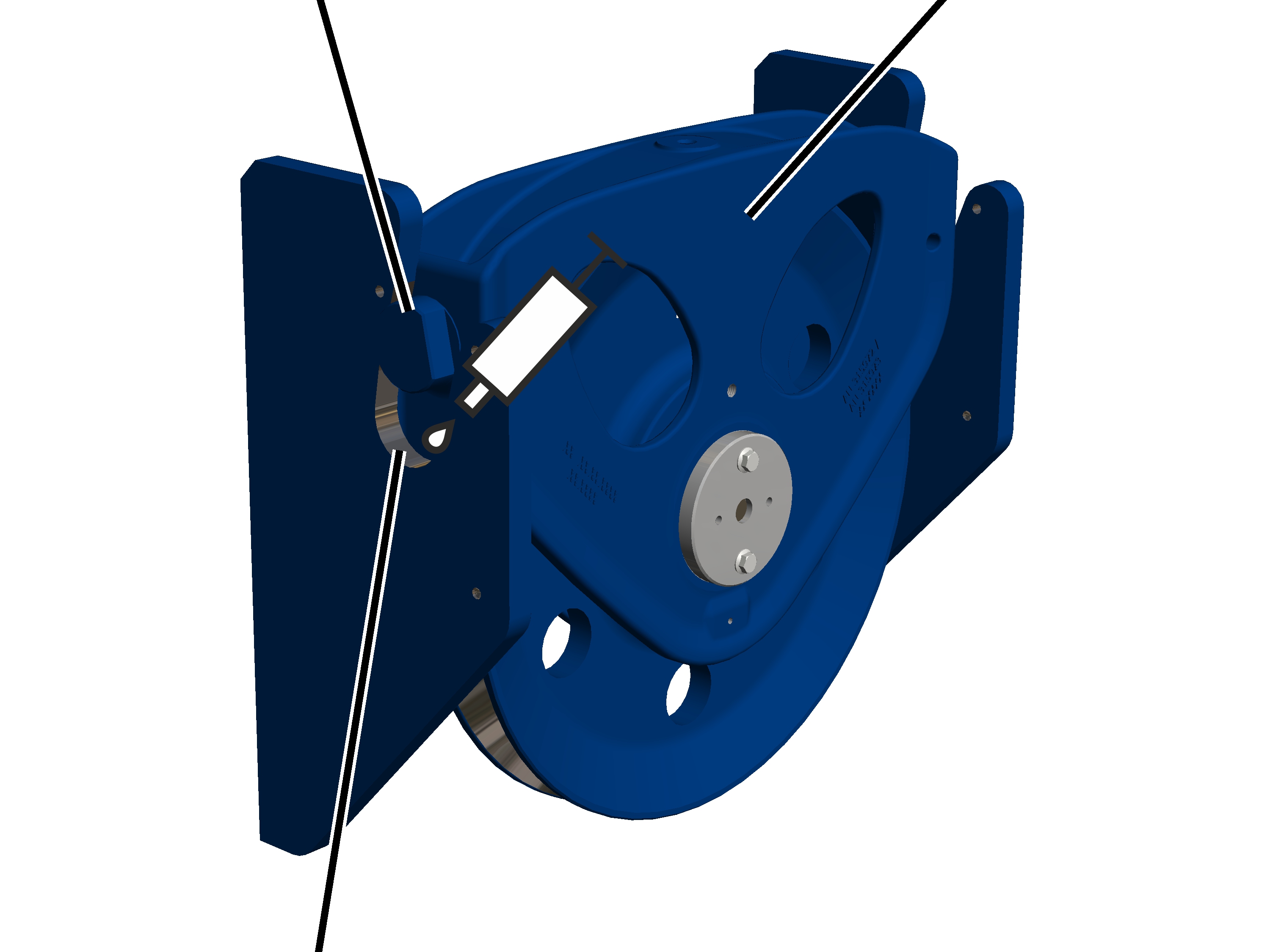
Release the rib screws (2x) on the cover.
Take the cover off the deflection roller crosshead.
|
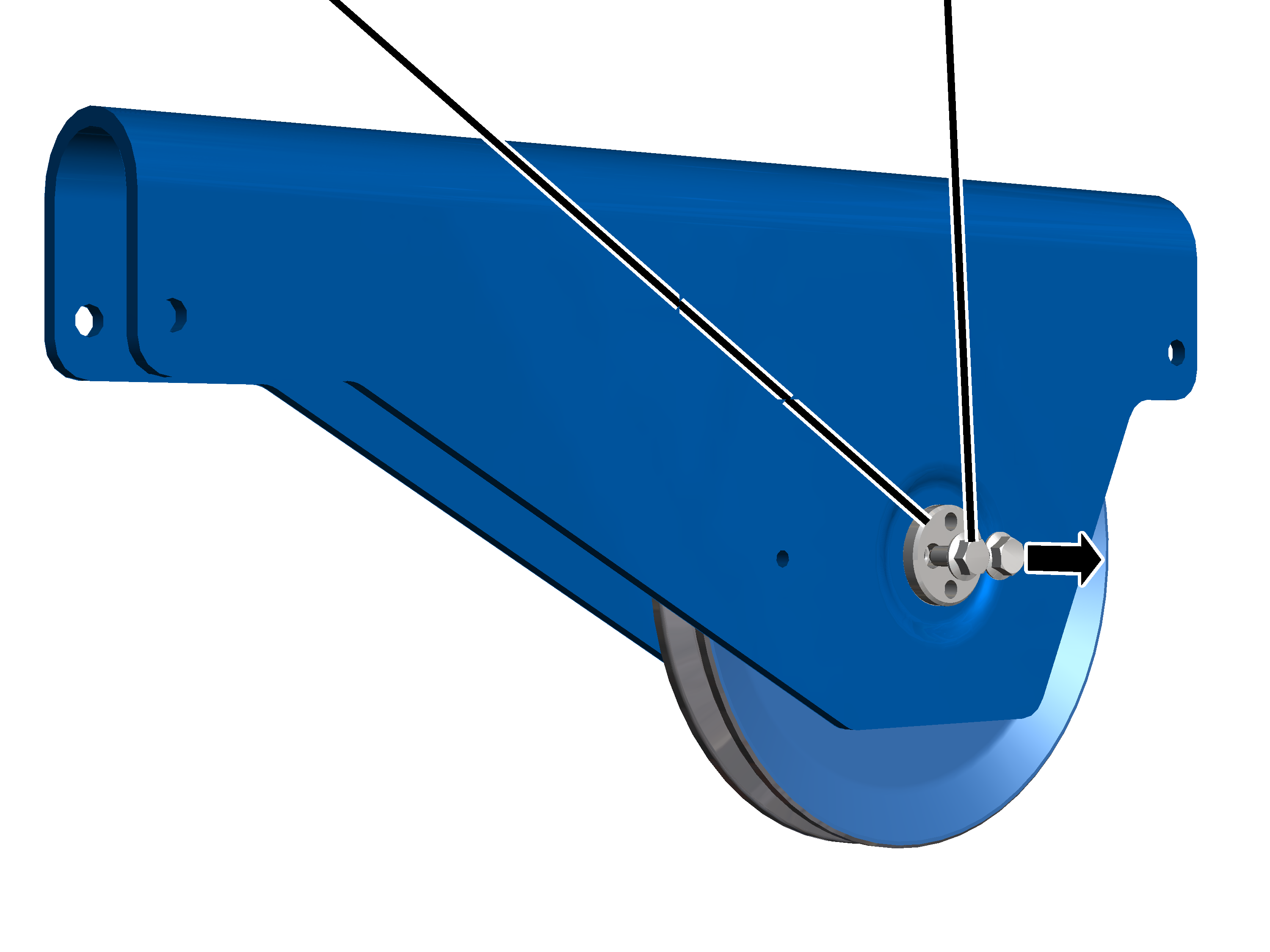
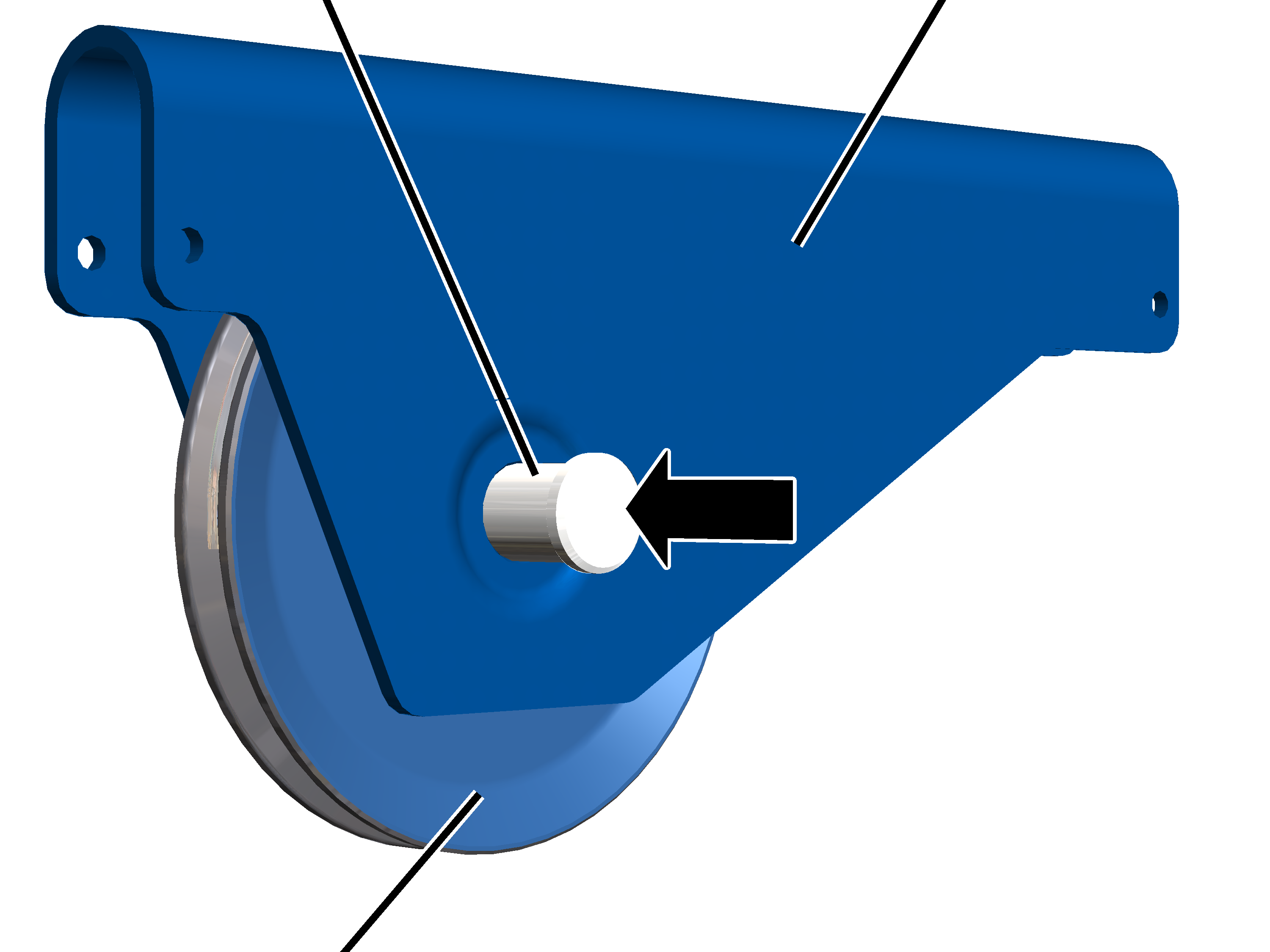
Deflection roller crosshead |
Bolt |
|
|
|
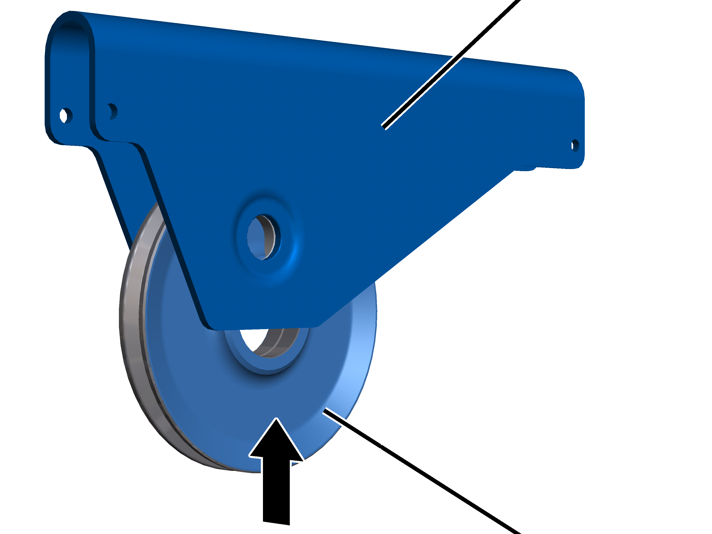
Deflection roller |
|
Pull the bolt out of the deflection roller crosshead and deflection
roller.
Pull the deflection roller out of the deflection roller
crosshead.
Only with wire rope hoist
with hoist drive GM 6000 and reeving 6/1
On a wire rope hoist with hoist drive GM 6000 and a
reeving 6/1, the deflection roller crossheads are welded to the trolley frame.
Only the deflection rollers themselves can therefore be replaced.
|
|
|
SL
safety clip |
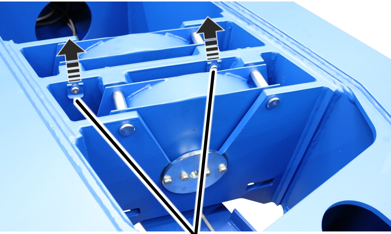
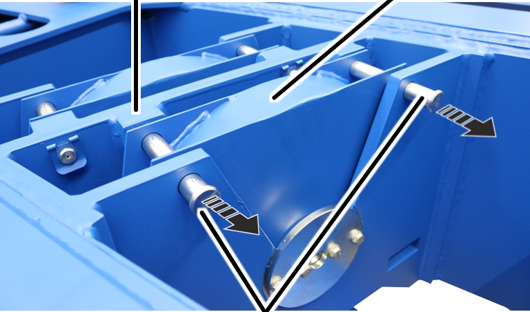
Pull the SL safety clip (2x) off the bolts (2x).
|
Crosshead |
Cover |
|
|
|
Bolt |
Pull the bolt out of the crosshead and the cover.
|
|
|
Deflection roller |
Cover |
Lift the cover off the deflection roller.
|
Cover |
Rib
screw M8x16 |
|
|
Release the rib screws M8x16 (4x) on the cover.
The outer rib screws can be removed fully. The inner rib screws
must stay loosely fastened on the cover because the cover is screwed to the
bolt.
|
|
Deflection roller |
|
|
|
Cover |
Crosshead |
Lift the deflection roller out of the crosshead.
|
|
|
Cover |
Rib
screw M8x16 |
Lay the deflection roller on an even surface with the bolt facing
downward.
Fully release the rib screws M8x16 (2x) on the cover.
|
|
Cover |
|
|
|
Bolt |
Deflection roller |
Lift the cover off the bolt.
|
|
Bolt |
|
|
|
Deflection roller |
|
Lift the deflection roller off the bolt.
Move exactly the same with the second deflection roller.
Assembling the
deflection roller
Only with wire rope hoist
with hoist drive GM 7000
|
Deflection roller crosshead |
Bolt |
|

|
|
Deflection
roller |
|
Push the deflection roller into the deflection roller crosshead.
|
Rib
screw |
|
|

|
|
Cover |
|
Screw the cover tight with the rib screws M10x20 on the bolt.
75 Nm.
Only with wire rope hoist
with hoist drive GM 6000 and reeving 6/1
On a wire rope hoist with hoist drive GM 6000 and a
reeving 6/1, the deflection roller crossheads are welded to the trolley frame.
Only the deflection rollers themselves can therefore be replaced.
Preparing the
deflection roller
With both deflection rollers:
|
|
Bolt |
|
|
|
Deflection roller |
|
Place the bolt on an even surface.
Lubricate the bolt.
Lubricant: “High temperature paste PBC 1574”. For details see Lubricants.
Push the deflection roller onto the bolt.
|
|
Cover |
|
|
|
Bolt |
Deflection roller |
Push the cover onto the bolt.
|

|
|
Cover |
Rib
screw M8x16 |
Loosely screw on the cover with rib screws M8x16 (2x).
Assembling the
deflection roller
|
Deflection roller |
|
|
|
|
Crosshead |
Cover |
Lift the deflection roller into the crosshead.
The cover must be in front of the crosshead suspension.
|
Rib
screw M8x16 |
Deflection roller |
|
|
|
Crosshead |
Cover |
Screw the deflection roller cover with rib screws M8x16 (2x) on the
crosshead. 42 Nm.
Tighten the rib screws M8x16 (2x) on the cover. 42 Nm.
|
|
Cover |
|
|
|
|
Deflection roller |
|
|
|
Place the cover on the deflection roller.
|
Crosshead |
Cover |
|
|
|
Bolt |
Push the bolts (2x) through the crosshead and the cover.
|
Bolt |
|
|
|
SL
safety clip |
Push the SL safety clips (2x) onto the bolt.
Move exactly the same with the second deflection roller.
Mounting the
deflection roller crosshead
Only with wire rope hoist
with hoist drive GM 7000 with reeving 4/1
On a wire rope hoist with hoist drive GM 7000 and a
reeving 4/1, the deflection roller crosshead is installed on the outside of the
trolley frame.
|
Bolt |
Deflection roller crosshead |
|
|
|
Bearing surface of the side panel |
|
|
|
|
Lubricate the bearing surface of the side panel.
Lubricant: “OKS 511 bonded coating”. For details, see Lubricants.
Let the bonded coating dry for 30 minutes!
Lubricate the side panel bearing surface again.
Lubricant: “High temperature paste PBC 1574”. For details, see
Lubricants.
|
Side
panel |
|
|
|
|
Deflection roller crosshead |
Lift the deflection roller crosshead into the side panel.
You must be able to move the deflection roller crosshead back
and forth by hand.
On both sides:
|
|
Side
panel |
|
|
|
Safety
plate |
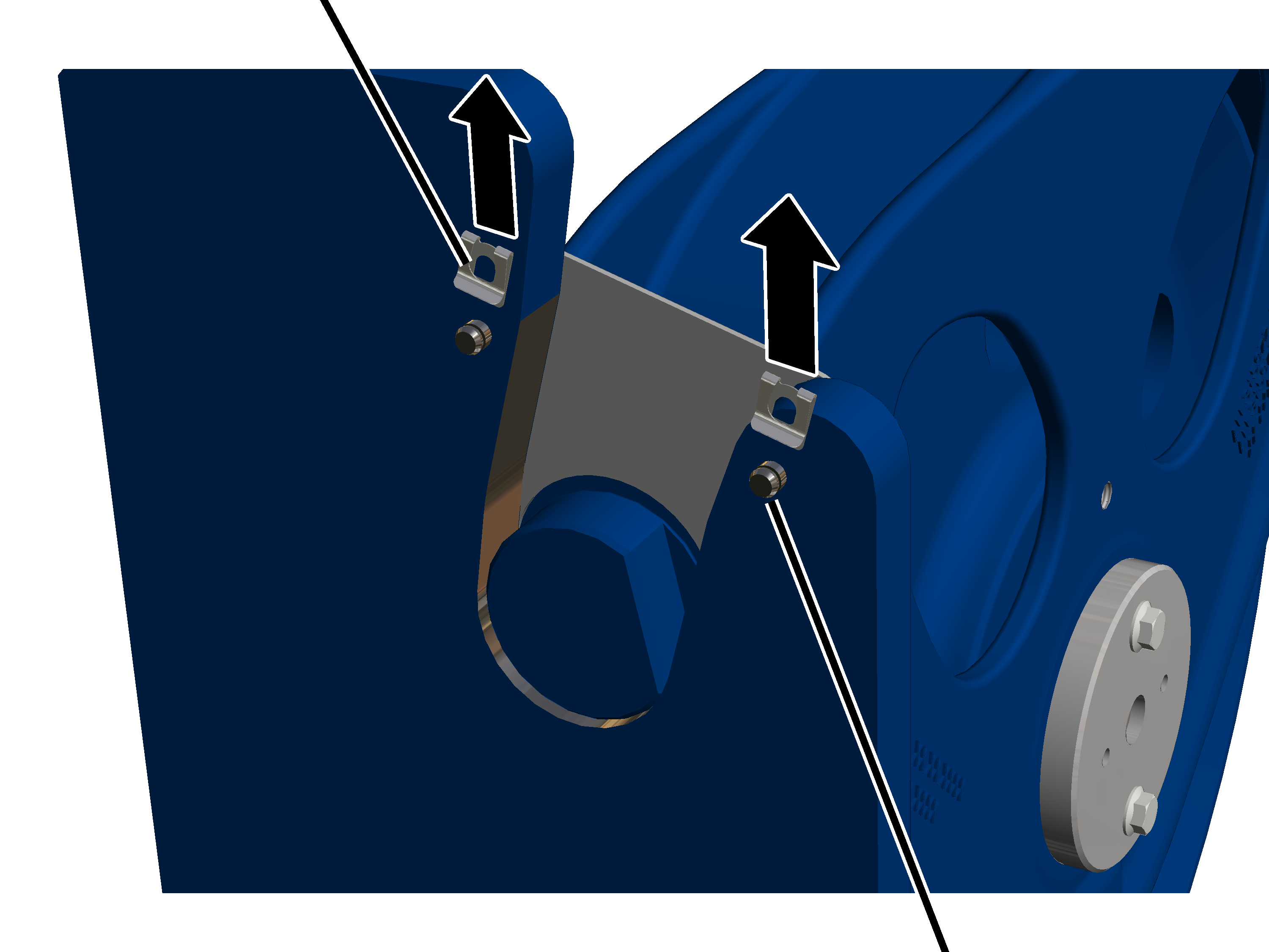
|
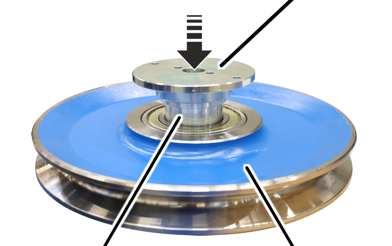
Push the safety plate into the side panel.
|
Safety
plate |
Bolt |
|
|
Push the bolt through the safety plate and the side panel.
|
SL
safety clip |
|
|
|
|
|
Bolt |
Push the SL safety clip onto the bolts.
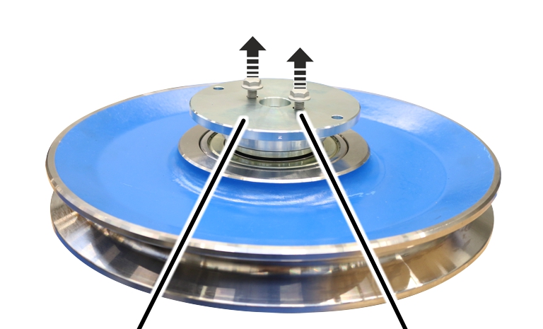
Only with wire rope hoist
with hoist drive GM 7000 and reeving 6/1
On a wire rope hoist with hoist drive GM 7000, the
deflection roller crossheads are installed in the trolley frame.
Fit the first deflection roller crosshead:
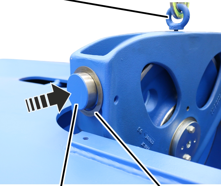
|
Lifting
tackle |
|
|
|
|
Bearing
bush |
Washer |
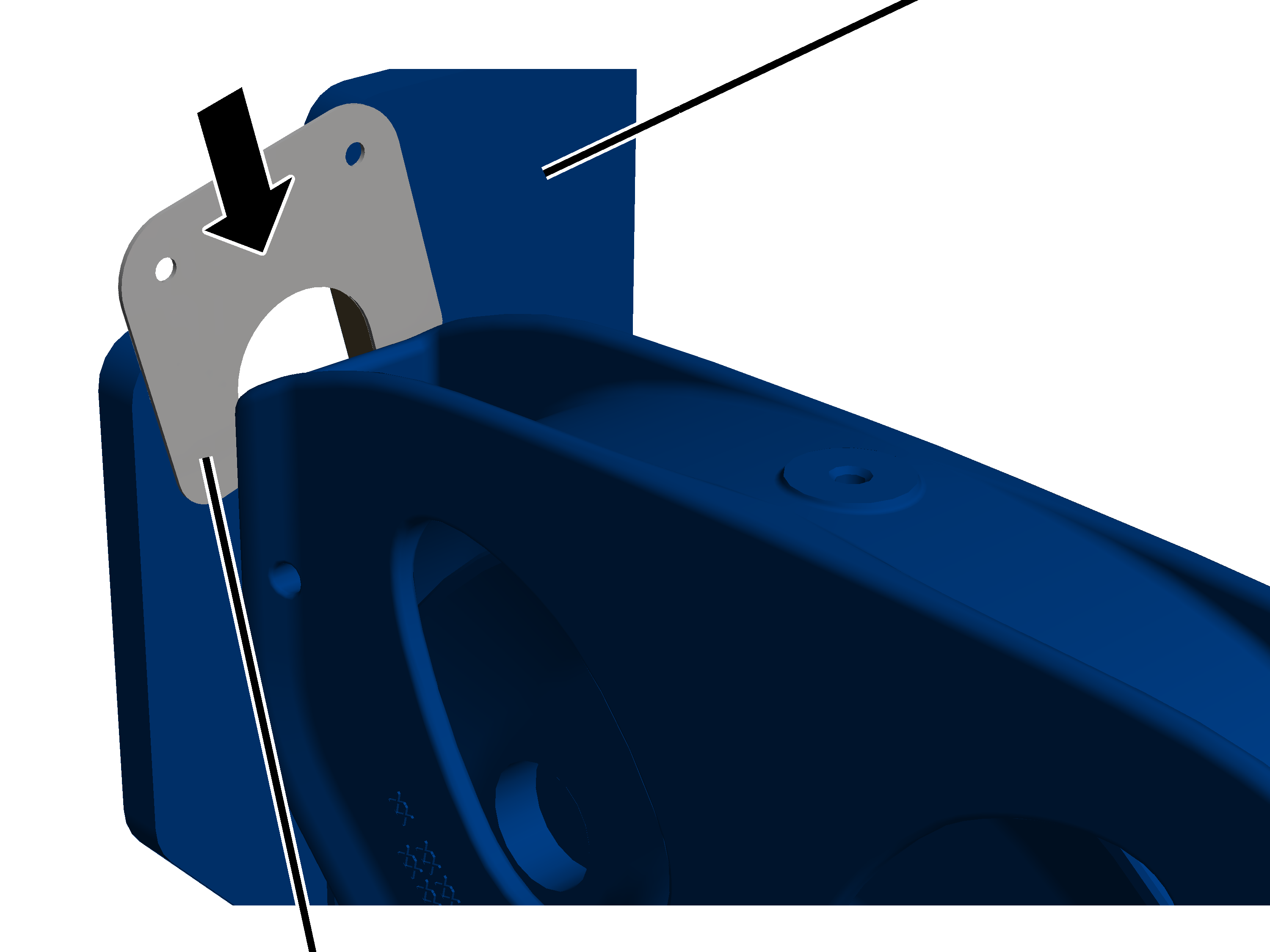
Push the washer (2x) onto both bearing bushes.
|
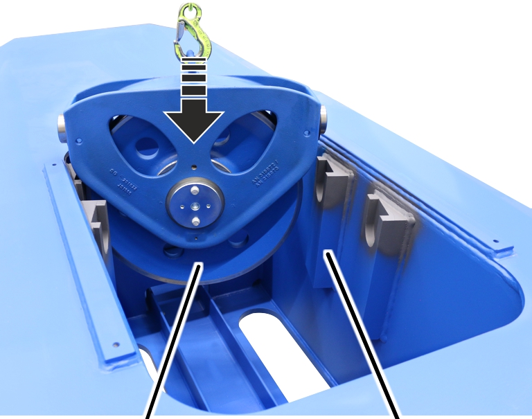
|
|
Deflection roller crosshead |
Suspension |
Lift the deflection roller crosshead into the trolley frame.
Fit the second deflection roller crosshead:
|
|
|
Bearing
bush |
Washer |
Push the washer (2x) onto both bearing bushes on the deflection
roller crosshead.
|
|
|
Second
deflection roller crosshead |
Suspension |
Lift the second deflection roller crosshead into the trolley
frame.
|
|
Metal
plate |
|
|
|
Rib
screws M10x16 |
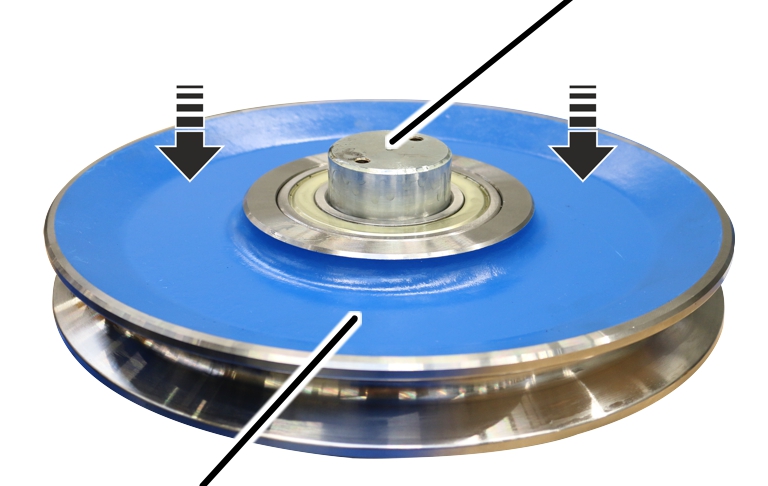
Place the plate on the trolley frame over the deflection roller
crossheads and screw in with rib screws M10x16 (4x). 75 Nm.