Air gap (between magnet body and anchor plate)
Brake lining thickness
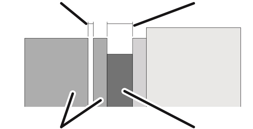
Magnet body and anchor plate
Brake rotor with brake lining
If the air gap is wider than permitted, it must be readjusted.
Overview:
|
Air gap (between magnet body and anchor plate) |
Brake lining thickness |
|
| |
|
Magnet body and anchor plate |
Brake rotor with brake lining |
|
Dimension |
Value |
|
Air gap between anchor plate and magnet body |
Between 0.3 mm and 1.1 mm |
|
Target value for air gap |
0.3 mm |
|
Brake lining thickness |
At least 7.5 mm |
|
Brake lining thickness |
New: 10.3 mm |
As soon as the travel motor stops running, the anchor plate presses against the brake rotor through spring force, braking the travel motor. An air gap appears between magnet body and anchor plate. When the travel motor starts up, the magnet body pulls the anchor plate off the brake rotor, allowing the travel motor to freely turn.
If the brake lining is worn, the air gap will be larger. See Inspecting the brake on the drive. If the air gap is larger than the maximum permitted, the brake must be readjusted. If the brake lining on the brake rotor is worn too thin, it must be replaced. See Replacing the brake rotor on the drive.
|
| |
|
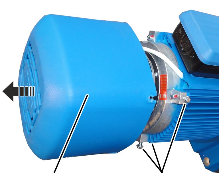
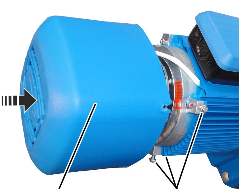
Fan cover |
Rib screws |
 Unscrew the rib screws (3x) of
the fan cover.
Unscrew the rib screws (3x) of
the fan cover.
Take off the fan cover.
|
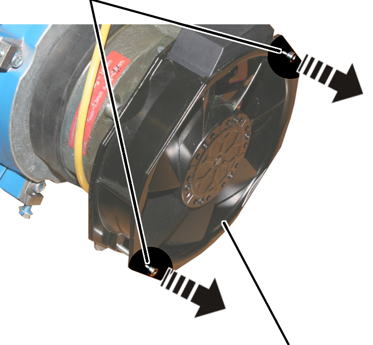
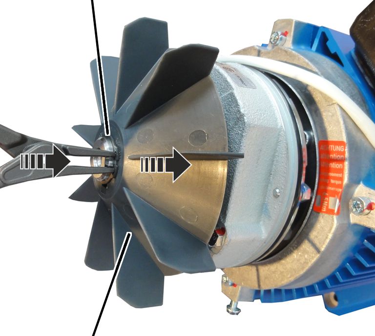
Circlip |
|
|
| |
|
Fan blade |
|
Remove the circlip.
 Remove the fan blade.
|
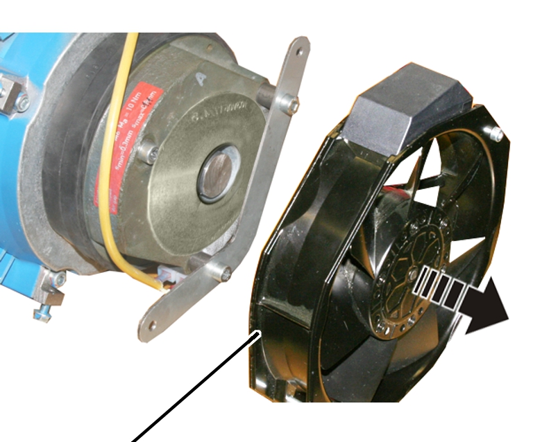
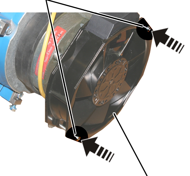
Screws |
|
|
| |
|
|
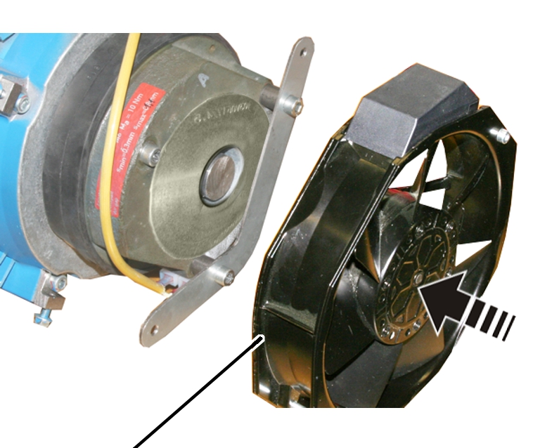
Auxiliary fan |
Disconnect the power supply of
the auxiliary fan.
Release the screws (2x) of the
auxiliary fan.
|
| |
|
Auxiliary fan |
|
Take off the auxiliary fan.
|
|
Mount | |
|
| ||
|
|
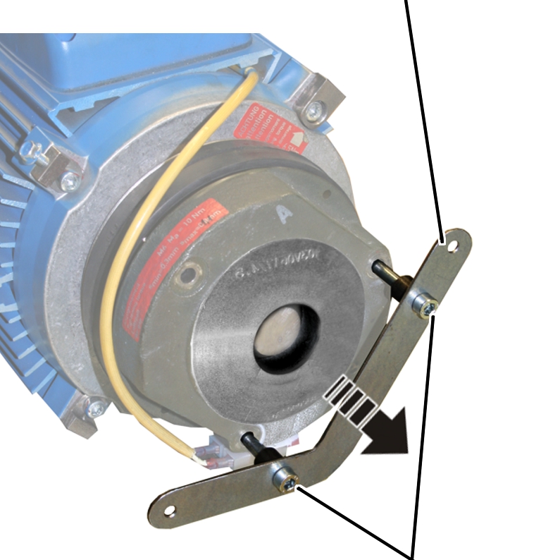
Fillister-head screws M6x80 | |
Release the fillister-head
screws M6x80 (2x) of the mount and remove the mount.
|
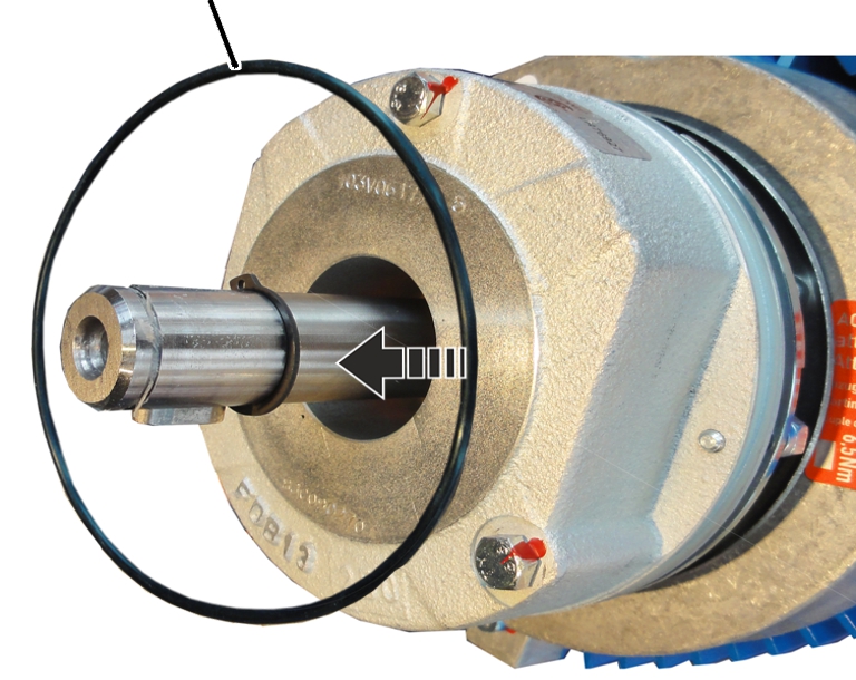
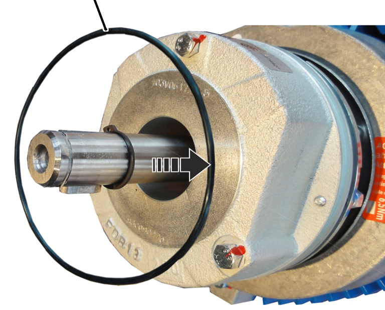
O-ring |
|
|
| |
Remove the O-ring.
|
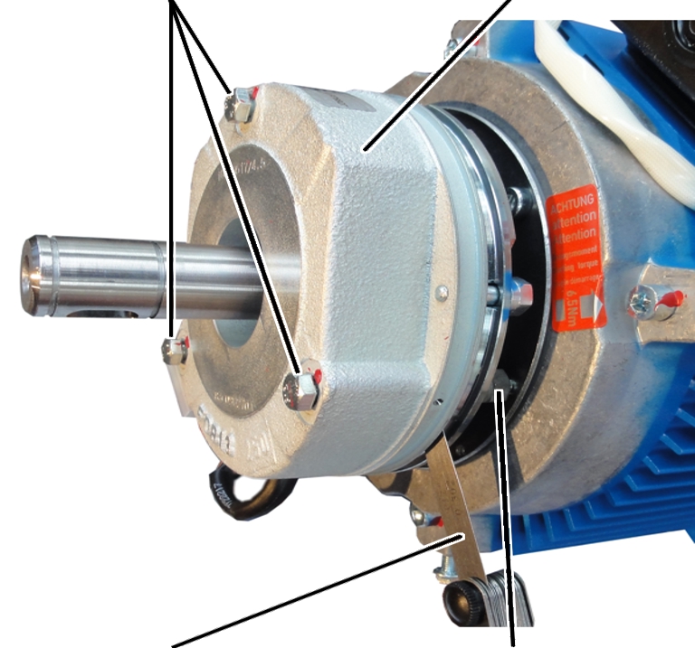
Hexagon head screws |
Magnet body |
|
| |
|
Feeler gauge |
Banjo bolt |
Unscrew the hexagon head screws (3x) by a half
turn.
Screw in the banjo bolts (3x) by
a half turn in the direction of the magnet body.
Read off the nominal width of
the air gap from the table.
|
Dimension |
Value |
|
Air gap between anchor plate and magnet body |
Between 0.3 mm and 1.1 mm |
|
Target value for air gap |
0.3 mm |
|
Brake lining thickness |
At least 7.5 mm |
|
Brake lining thickness |
New: 10.3 mm |
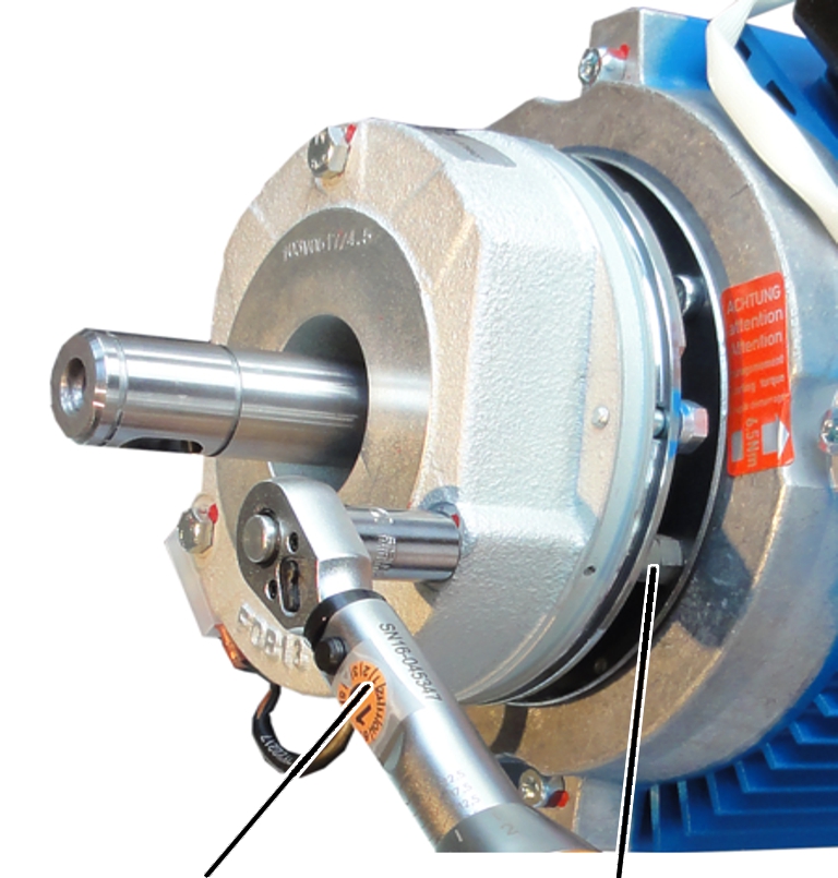
 Tighten the hexagon head screws
so that the feeler gauge can still be pulled from the air gap.
Tighten the hexagon head screws
so that the feeler gauge can still be pulled from the air gap.
● The air gap on this hexagon head screw is now adjusted to the set width.
Repeat the steps for all hexagon
head screws (3x).
|
| |
|
Torque wrench |
Banjo bolt |
Screw in the banjo bolts (3x) in the direction of
the travel motor until hand-tight.
Screw on the hexagon head screws
M6x70 (3x). 7 Nm.
|
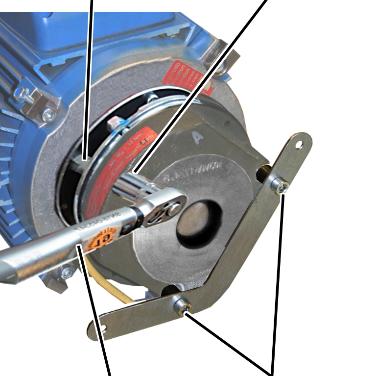
Banjo bolts |
Hexagon head screw M6x70 |
|
| |
|
Torque wrench |
Fillister-head screws M6x80 |
Screw in the banjo bolts (3x) in
the direction of the travel motor until hand-tight.
Screw on the fillister-head
screws M6x80 (2x). 10 Nm.
Screw on the hexagon head screw
M6x70 (1x). 7 Nm.
● The brake is fixed with screws.
Check the air gap next to all
three hexagon head screws. If different than the set width, repeat the
adjustment.
|
O-ring |
|
|
| |
Insert the O-ring.
|
Circlip |
|
|
| |
|
Fan blade |
|
Place the fan blade on the motor
shaft.
Insert the circlip.
|
| |
|
Auxiliary fan |
|
Place the auxiliary fan on the
mount.
|
Fillister-head screws M4 |
|
|
| |
|
|
Auxiliary fan |
Screw the auxiliary fan in place
with the fillister-head screws M4 (2x). 1.5 Nm.
Connect the power supply of the
auxiliary fan.
|
| |
|
Fan cover |
Rib screws |
Attach fan cover.
Screw in the rib screws (3x) of
the fan cover.