Air gap (between magnet body and anchor plate)
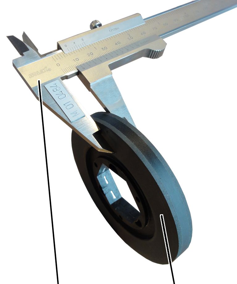
Brake lining thickness
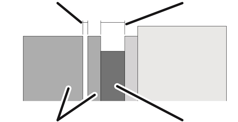
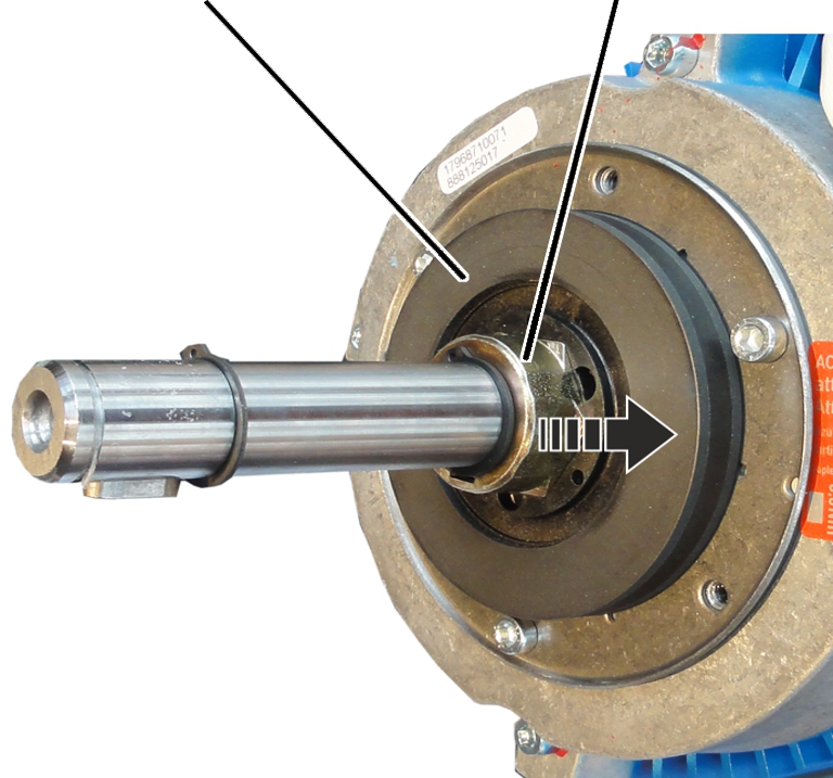
Magnet body and anchor plate
Brake rotor with brake lining
|
Air gap (between magnet body and anchor plate) |
Brake lining thickness |
|
| |
|
Magnet body and anchor plate |
Brake rotor with brake lining |
|
Value | |
|
Air gap between anchor plate and magnet body |
Between 0.3 mm and 1.1 mm |
|
Target value for air gap |
0.3 mm |
|
Brake lining thickness |
At least 7.5 mm |
|
Brake lining thickness |
New: 10.3 mm |
This is the point at which the air gap must be readjusted at the latest. If the minimum lining thickness has been reached, the brake rotor must be replaced.
|
| |
|
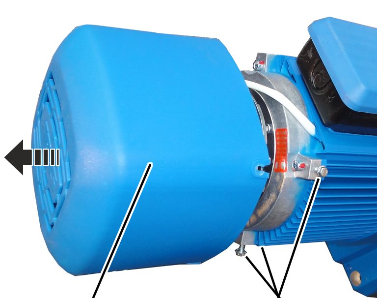
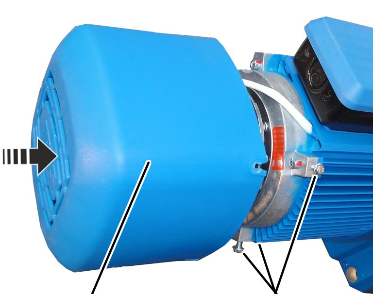
Fan cover |
Rib screws |
 Unscrew the rib screws (3x) of
the fan cover.
Unscrew the rib screws (3x) of
the fan cover.
Take off the fan cover.
|
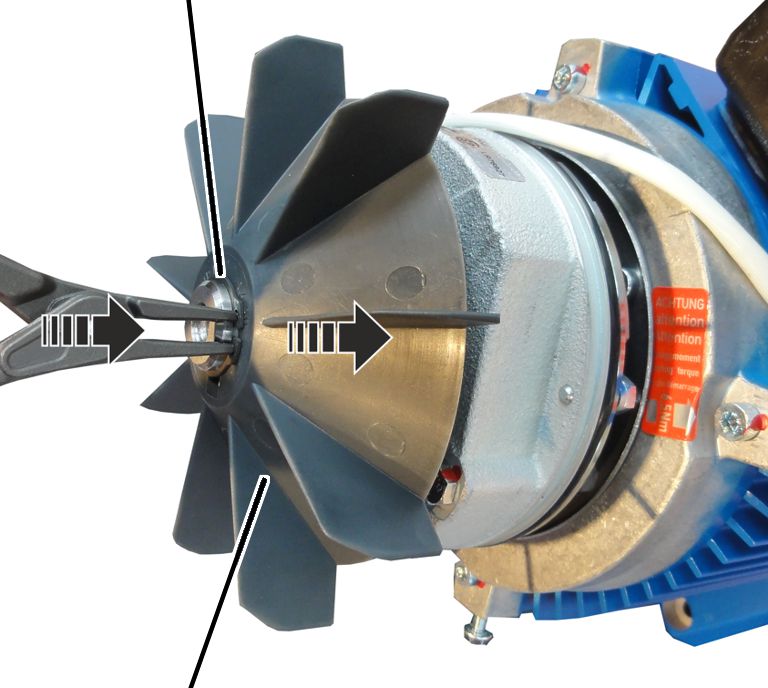
Circlip |
|
|
| |
|
Fan blade |
|
Remove the circlip.
Remove the fan blade.
|
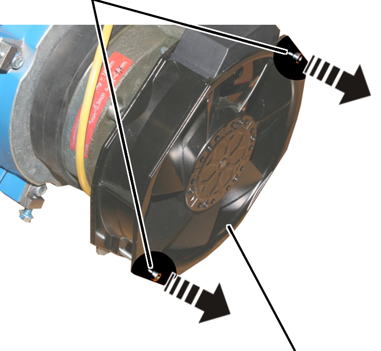
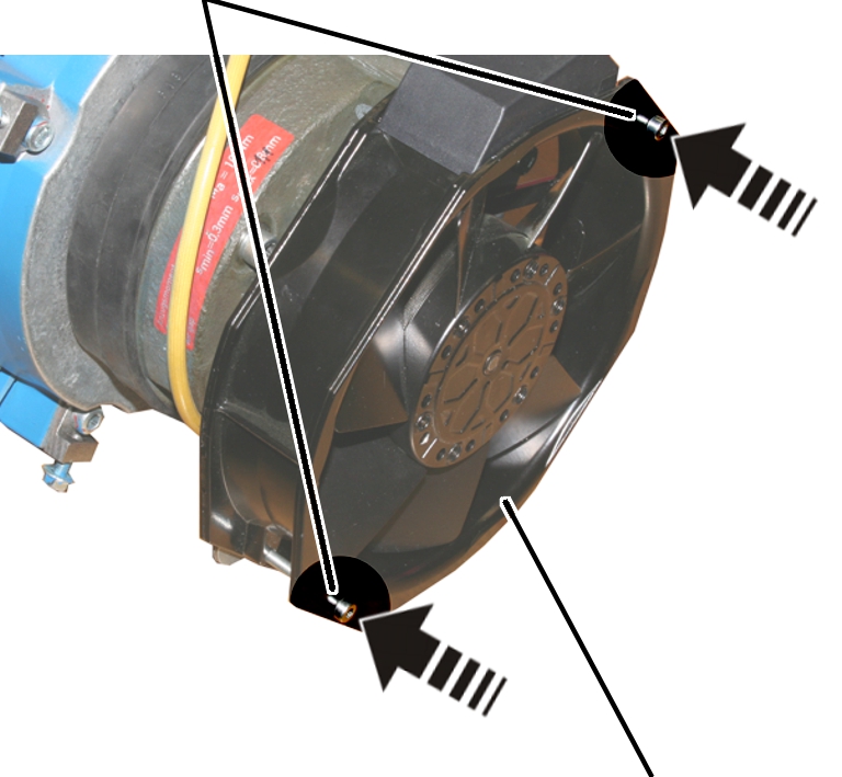
Screws |
|
|
| |
|
|
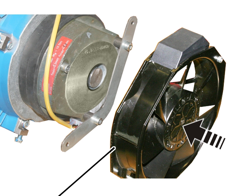
Auxiliary fan |
Disconnect the power supply of
the auxiliary fan.
Release the screws (2x) of the
auxiliary fan.
|
| |
|
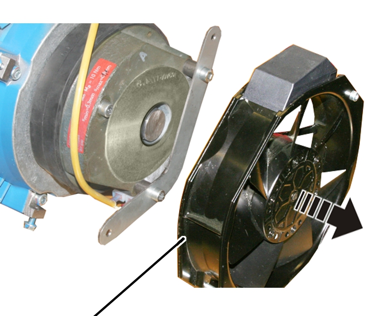
Auxiliary fan |
|
Take off the auxiliary fan.
|
|
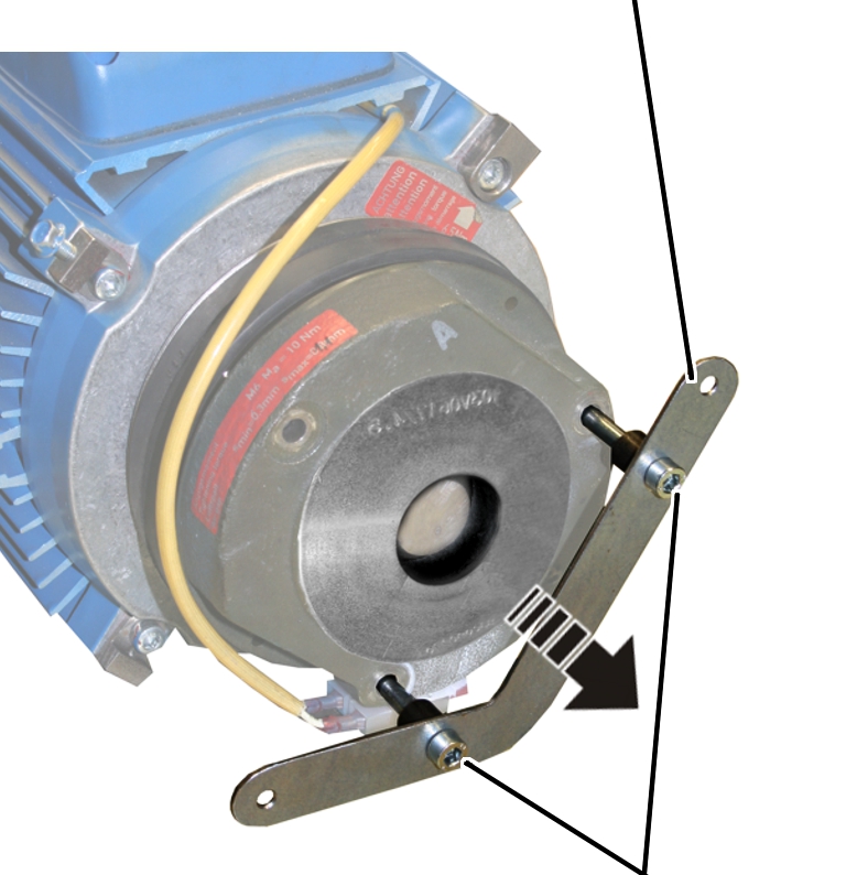
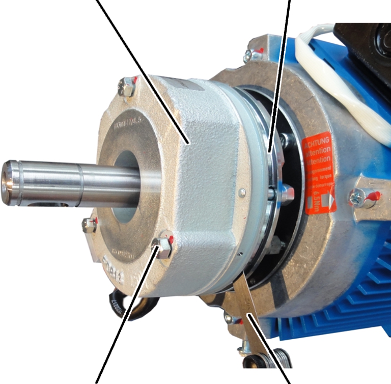
Mount |
|
| |
|
|
Fillister-head screws M6x80 |
 Release the fillister-head
screws M6x80 (2x) of the mount and remove the mount.
Release the fillister-head
screws M6x80 (2x) of the mount and remove the mount.
|
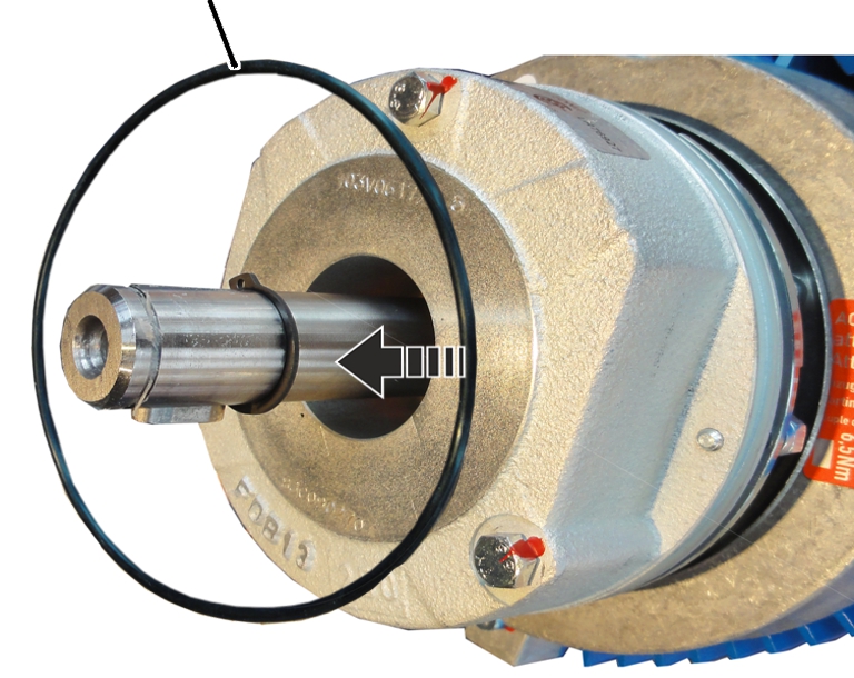
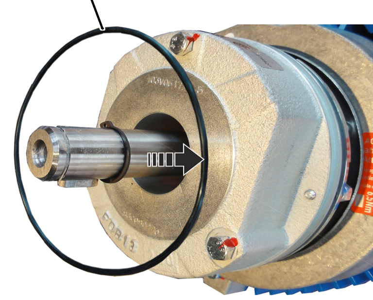
O-ring |
|
|
| |
Remove the O-ring.
|
Magnet body |
Anchor plate |
|
| |
|
Hexagon head screw M6x70 |
Feeler gauge |
 If the air gap has reached the
maximum width of the operating range (1.1 mm), adjust the brake. See Setting the air gap on
the brake.
If the air gap has reached the
maximum width of the operating range (1.1 mm), adjust the brake. See Setting the air gap on
the brake.
If the width of the air gap is within the permitted range but usage behaviour leads to the expectation that the air gap will be wider than permitted before the next regular inspection, the air gap must be readjusted now.
Repeat
the steps for all hexagon head screws (3x).
Clean the entire brake with
compressed air.
|
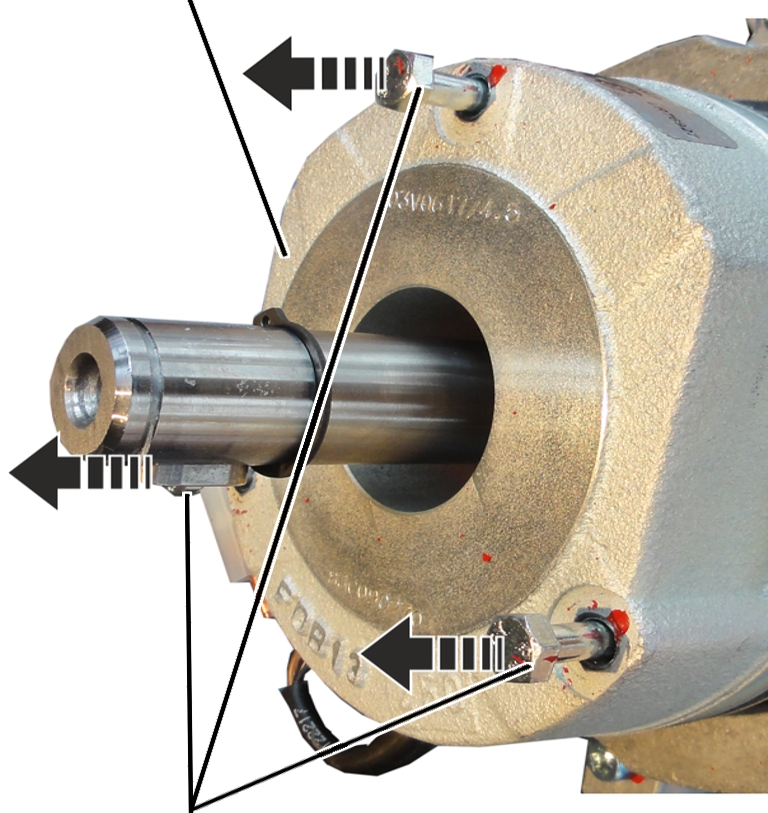
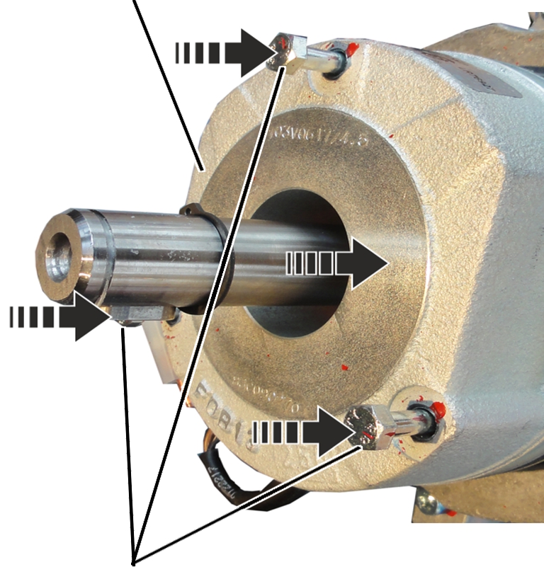
Magnet body |
|
|
| |
|
Hexagon head screws M6x70 |
|
Disconnect the power supply of the magnet
body.
Release the hexagon head screws
M6x70 (3x).
Pull the magnet body from the
motor shaft.
|
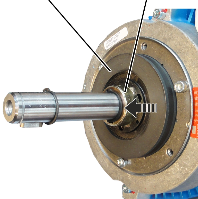
Hub | |
|
| |
Pull the brake rotor from the
hub and from the motor shaft.
|
| |
|
Calliper |
Brake rotor |
Check the thickness of the brake
lining with a calliper.
If the brake rotor is thinner
than 7.5 mm: replace the brake rotor. See Replacing the brake rotor on the
drive.
The area (air gap) between the magnet body and the anchor plate is protected from dust by an O-ring. The O-ring must not become damaged or missing.
Check the O-ring.
The O-ring must not be torn, dented or damaged in any other way, nor be missing completely.
If the O-ring is damaged or
missing, fit a new O-ring. See ABUS
Service.
|
Brake rotor |
Hub |
|
| |
Slide the brake rotor over the
motor shaft onto the hub.
|
Magnet body |
|
|
| |
|
Hexagon head screws M6x70 |
|
Slide the magnet body onto the
motor shaft.
Screw on the hexagon head screws
M6x70 (3x). 7 Nm.
Then the air gap must be
readjusted. See Setting the air gap on the brake.
Connect the power supply of the
magnet body.
|
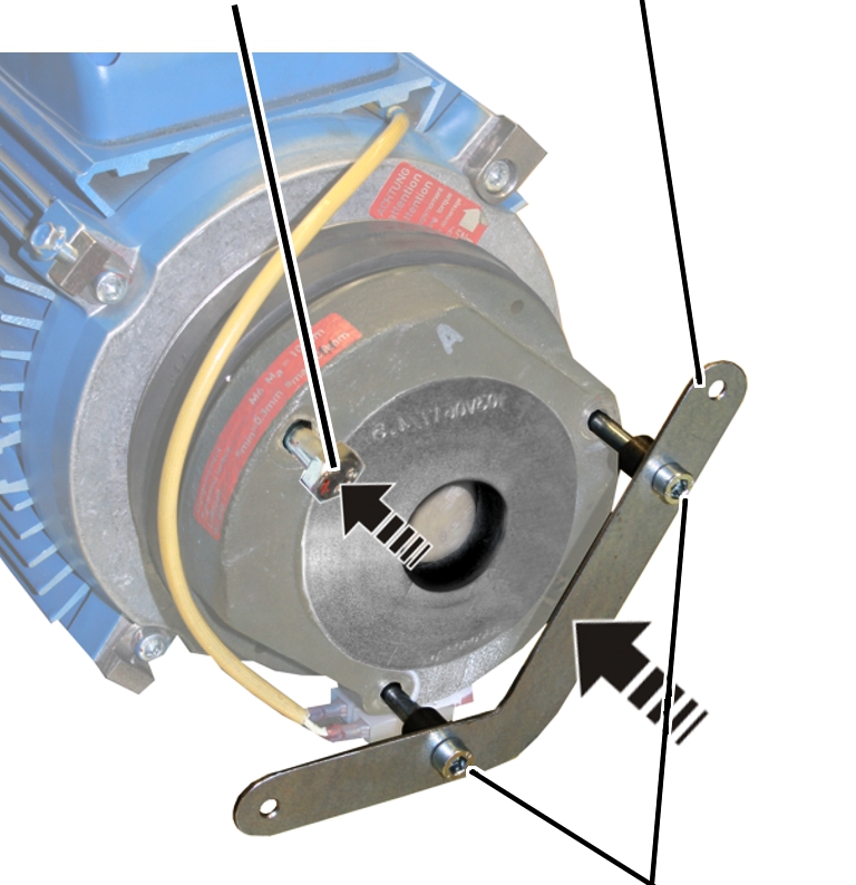
Hexagon head screw M6x70 |
Mount |
|
| |
|
|
Fillister-head screws M6x80 |
Slide the magnet body onto the
motor shaft.
Screw on the mount with the
fillister-head screws M6x80 (2x). 10 Nm.
Screw on the hexagon head screw
M6x70 (1x). 7 Nm.
Then the air gap must be
readjusted. See Setting the air gap on the brake.
Connect the power supply of the
magnet body.
|
O-ring |
|
|
| |
Insert the O-ring.
|
Circlip |
|
|
| |
|
Fan blade |
|
Place the fan blade on the motor
shaft.
Insert the circlip.
|
| |
|
Auxiliary fan |
|
Place the auxiliary fan on the
mount.
|
Fillister-head screws M4 |
|
|
| |
|
|
Auxiliary fan |
Screw the auxiliary fan in place
with the fillister-head screws M4 (2x). 1.5 Nm.
Connect the power supply of the
auxiliary fan.
|
| |
|
Fan cover |
Rib screws |
Attach fan cover.
Screw in the rib screws (3x) of
the fan cover.