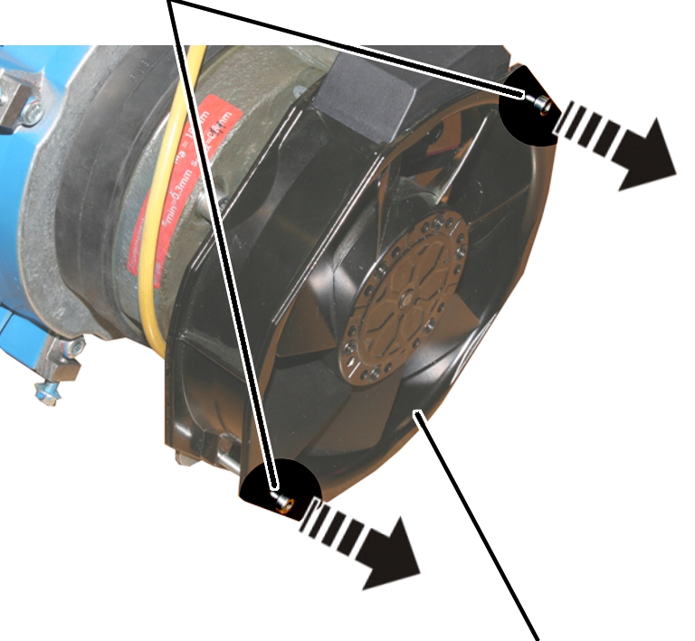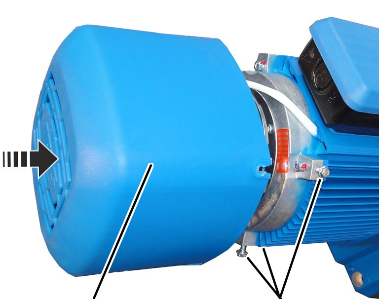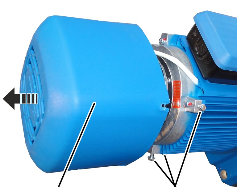
Fan cover
Rib screws
If the brake rotor is thinner than permitted, the brake may not be readjusted again. In this case, the brake rotor must be replaced.
Depending on wear and necessity, additional parts of the brake may need to be replaced.
─ Friction disc
─ Hub
─ O-ring
─ Banjo bolts
─ Feather key
─ Circlip
─ Magnet body
|
| |
|
Fan cover |
Rib screws |
 Unscrew the rib screws (3x) of
the fan cover.
Unscrew the rib screws (3x) of
the fan cover.
Take off the fan cover.
|
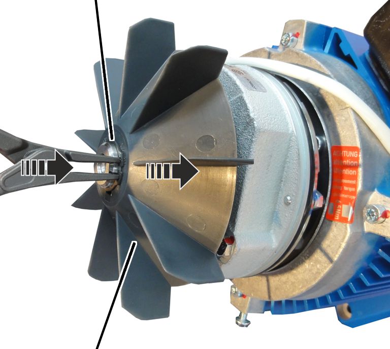
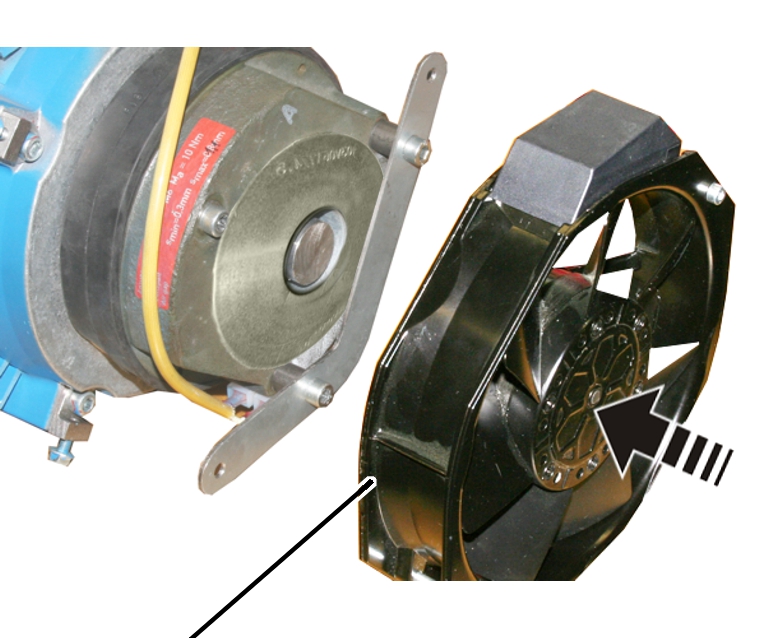
Circlip |
|
|
| |
|
Fan blade |
|
Remove the circlip.
Remove the fan blade.
|
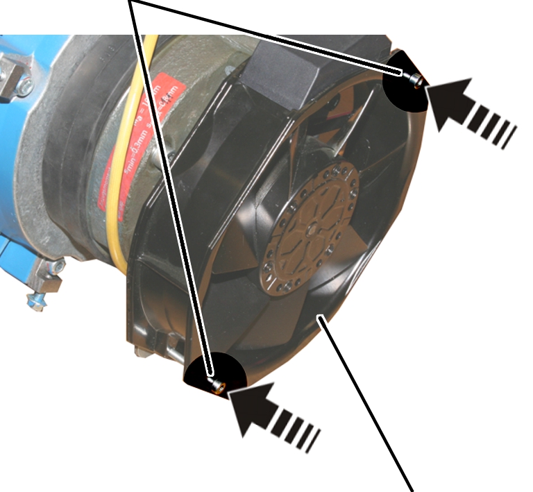
Screws |
|
|
| |
|
|
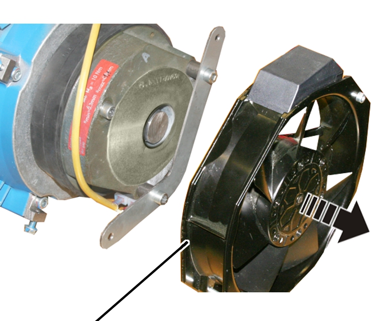
Auxiliary fan |
Disconnect the power supply of
the auxiliary fan.
Release the screws (2x) of the
auxiliary fan.
|
| |
|
Auxiliary fan |
|
Take off the auxiliary fan.
|
|
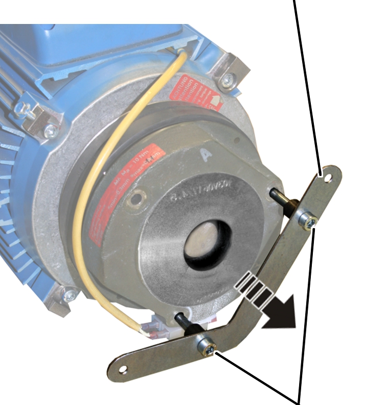
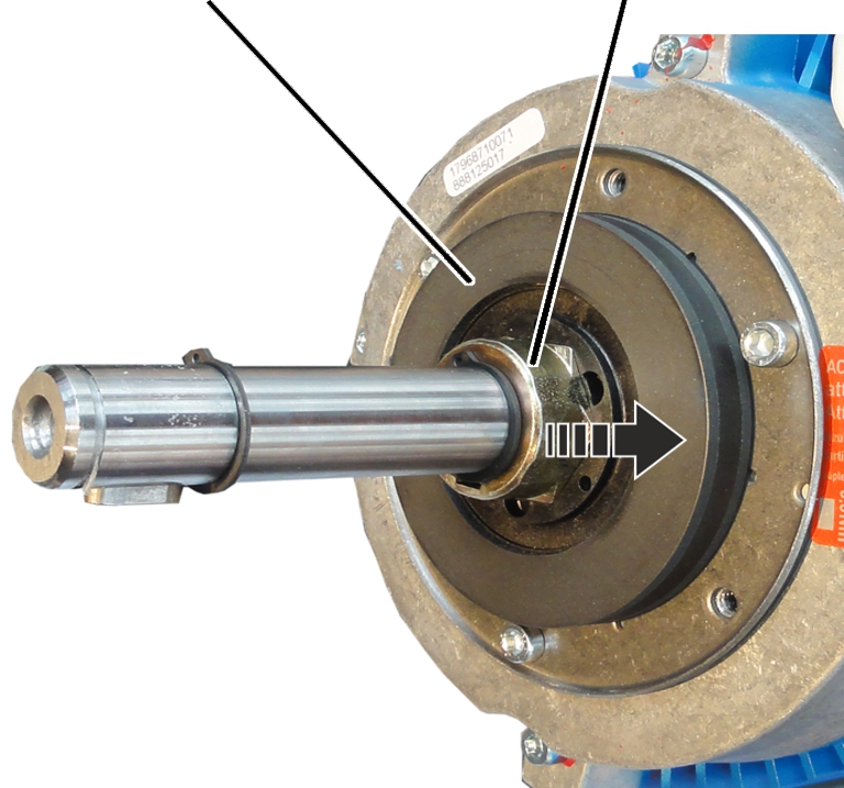
Mount |
|
| |
|
|
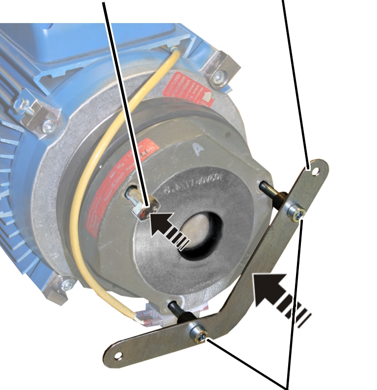
Fillister-head screws M6x80 |
Release the fillister-head
screws M6x80 (2x) of the mount and remove the mount.
|
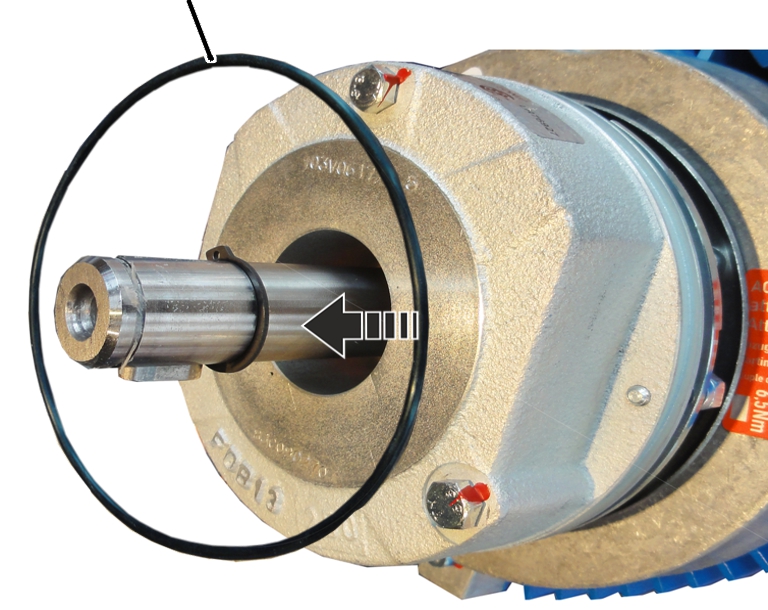
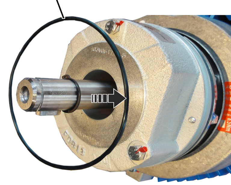
O-ring |
|
|
| |
Remove the O-ring.
|
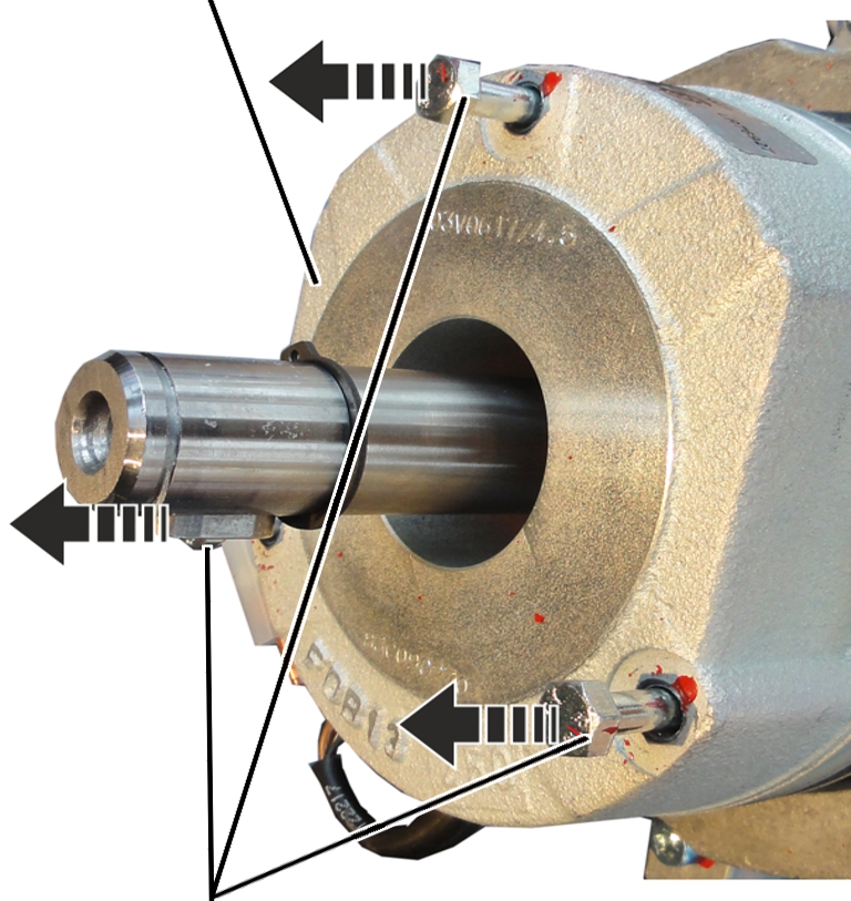
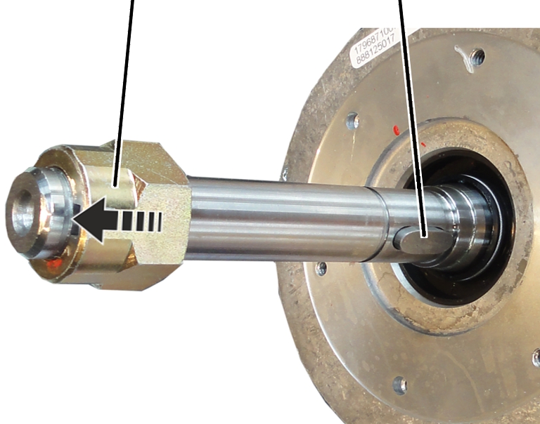
Magnet body |
|
|
| |
|
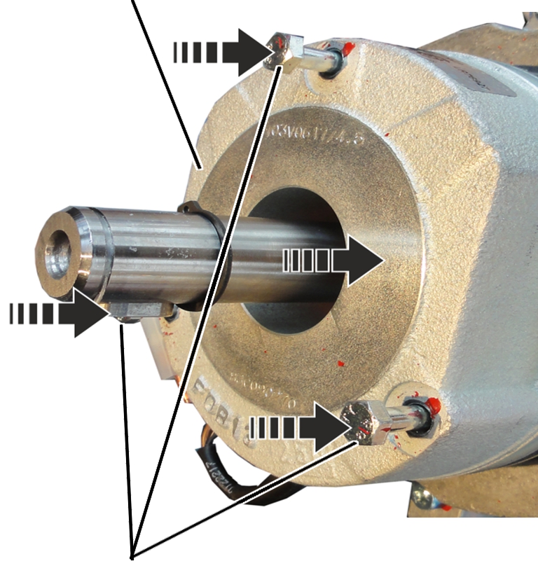
Hexagon head screws M6x70 |
|
 Disconnect the power supply of
the magnet body.
Disconnect the power supply of
the magnet body.
Release the hexagon head screws
M6x70 (3x).
Pull the magnet body from the
motor shaft.
|
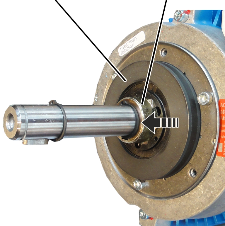
Brake rotor |
Hub |
|
| |
Pull the brake rotor from the
hub and from the motor shaft.
|
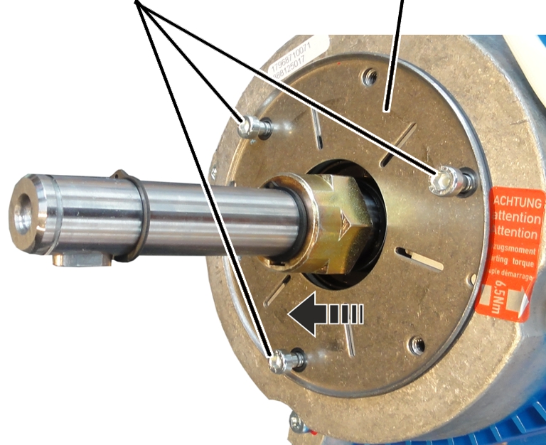
Fillister-head screws |
Friction disc |
|
| |
Loosen the fillister-head screws
(3x).
Remove the friction disc.
|
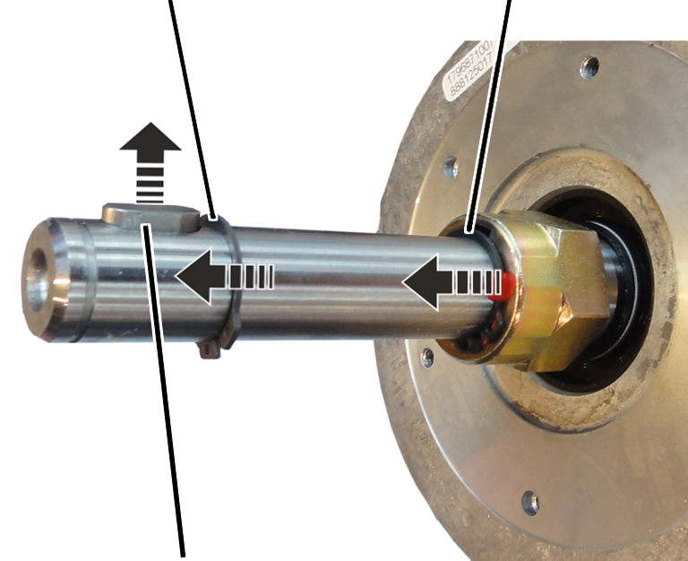
Front circlip |
Rear circlip |
|
| |
|
Feather key |
|
Remove the front feather
key.
Remove the front circlip.
Remove the rear circlip.
|
Hub |
Rear feather key |
|
| |
Pull the hub from the motor
shaft.
● The brake is completely disassembled.
|
Hub |
Rear feather key |
|
| |
Slide the new hub over the rear
feather key onto the motor shaft.
|
Front circlip |
Rear circlip |
|
| |
|
Feather key |
|
Insert the rear circlip.
Insert the front circlip.
Insert the front feather
key.
|
Fillister-head screws |
Friction disc |
|
| |
Slide on the new friction
disc.
Tighten the fillister-head
screws (3x).
|
Brake rotor |
Hub |
|
| |
Slide the brake rotor over the
motor shaft onto the hub.
|
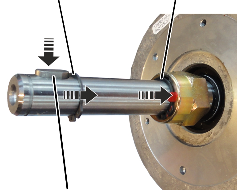
Magnet body |
|
|
| |
|
Hexagon head screws M6x70 |
|
Slide the magnet body onto the
motor shaft.
Screw on the hexagon head screws
M6x70 (3x). 7 Nm.
Then the air gap must be
readjusted. See Setting the air gap on the brake.
Connect the power supply of the
magnet body.
|
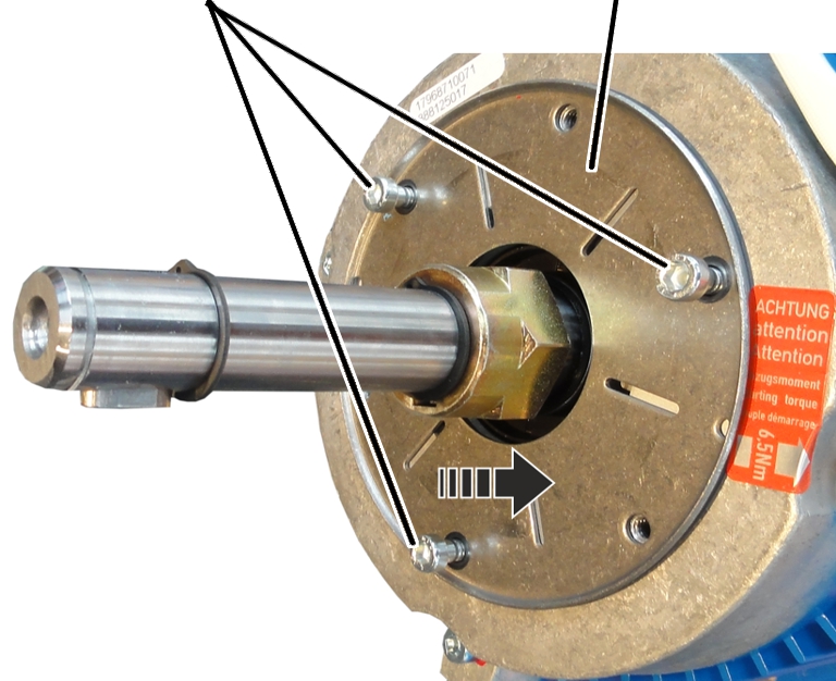
Hexagon head screw M6x70 |
Mount |
|
| |
|
|
Fillister-head screws M6x80 |
Slide the magnet body onto the
motor shaft.
Screw on the mount with the
fillister-head screws M6x80 (2x). 10 Nm.
Screw on the hexagon head screw
M6x70 (1x). 7 Nm.
Then the air gap must be
readjusted. See Setting the air gap on the brake.
Connect the power supply of the
magnet body.
If necessary, replace the
hexagon head screws M6x70 and banjo bolts with new ones.
|
O-ring |
|
|
| |
Insert the O-ring.
|
Circlip |
|
|
| |
|
Fan blade |
|
Place the fan blade on the motor
shaft.
Insert the circlip.
|
| |
|
Auxiliary fan |
|
Place the auxiliary fan on the
mount.
|
Fillister-head screws M4 |
|
|
| |
|
|
Auxiliary fan |
Screw the auxiliary fan in place
with the fillister-head screws M4 (2x). 1.5 Nm.
Connect the power supply of the
auxiliary fan.
|
| |
|
Fan cover |
Rib screws |
Attach fan cover.
Screw in the rib screws (3x) of
the fan cover.