Comply with occupational
health and safety requirements.
Comply with occupational
health and safety requirements.If the wheel is damaged or worn, it must be replaced by a new wheel.
The figures show the disassembly of a size 130 wheel. The removal of larger wheels does not essentially differ from this.
Comply with occupational
health and safety requirements.
Prop up the end carriage close
to the wheel.
|
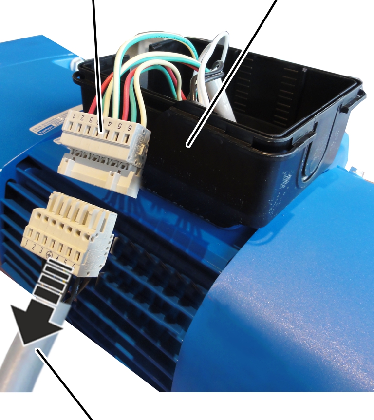
Connector housing | ||
|
| ||
|
Connection cable |
| |
Open the connector housing to
the drive.
Disconnect the connection cable
from the coupler plug.
Determine the weight of the drive. See the
ABUS Drive product manual.
|
|
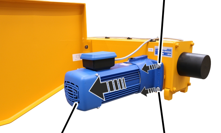
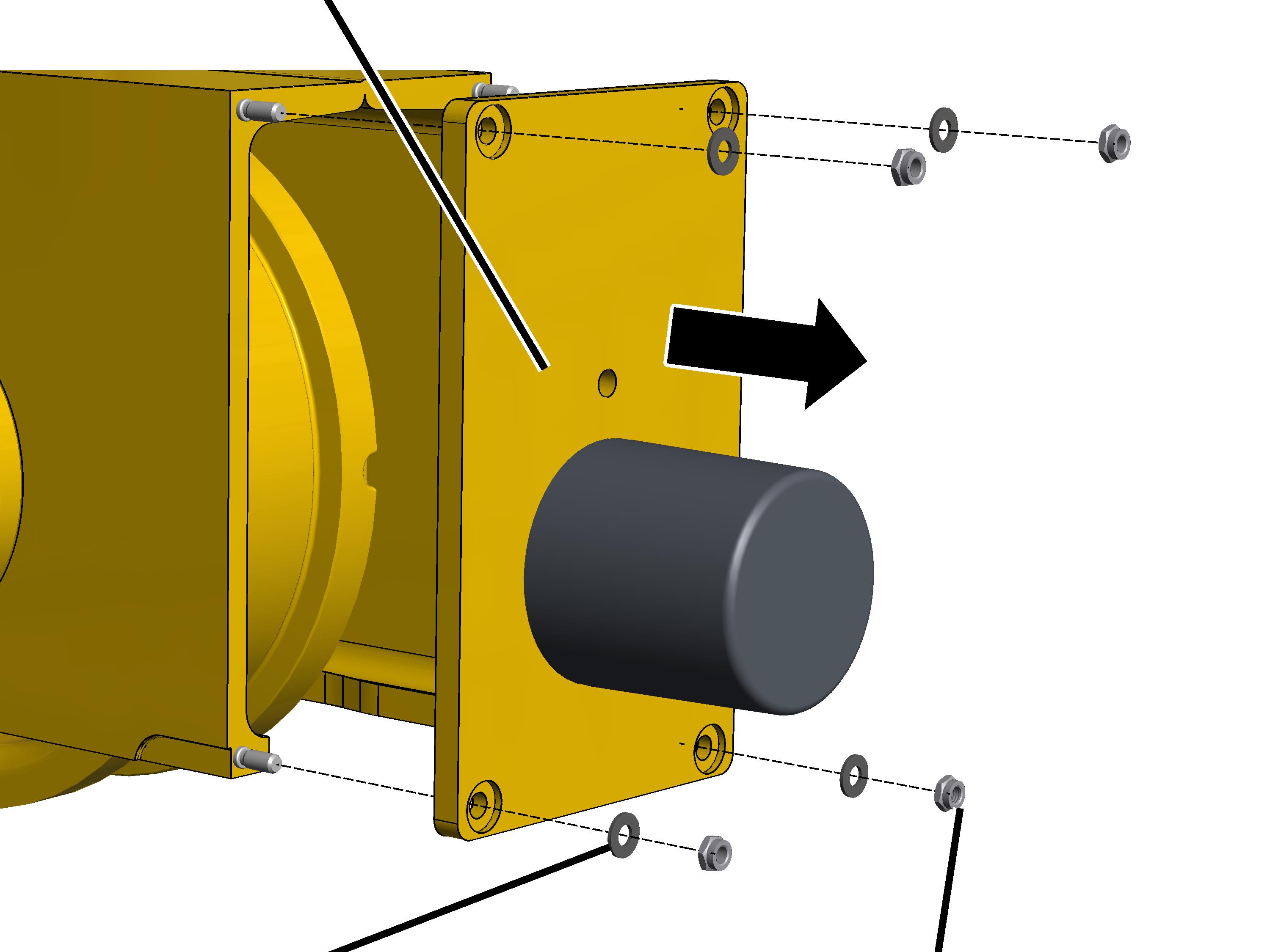
Rib screws | |
|
| ||
|
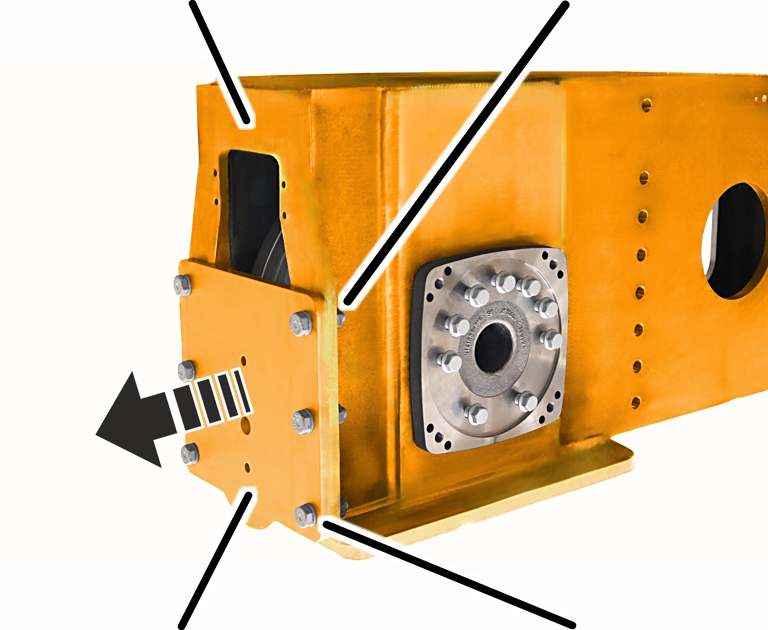
Crane travel drive |
Rib screws | |
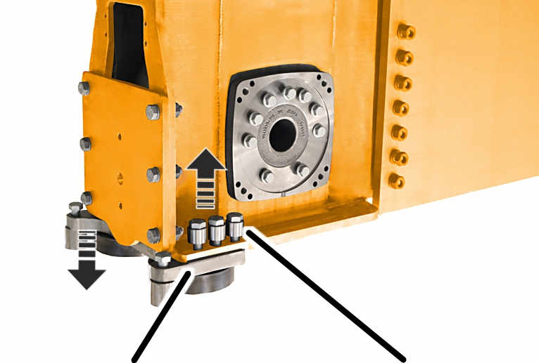
Unscrew the rib screws (4x).
Pull out the crane travel
drive.
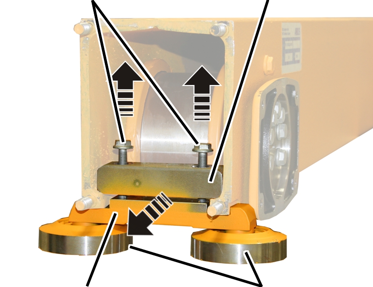
This work step applies only to end carriages of the sizes 130 to 420.
|
Buffer plate |
|
|
| |
|
Plastic washer |
Self-locking nut |
Unscrew the self-locking nuts
(4x).
Remove the plastic washers
(4x).
Remove the buffer plate.
This section only applies if the end carriage has guide rollers or a derailing protection device. This work step also applies to end carriages of the sizes 280, 350 and 420.
|
Screws |
Clamping element | |
|
| ||
|
Bracket with guide rollers, clamping piece, derailing protection device |
Guide rollers | |
Release screws (2x).
Take out the bracket with guide
rollers, derailing protection device or clamping piece.
This work step only applies if the size 500 end carriage has guide rollers.
|
| |
|
Bracket |
High-tensile bolt M20x70 with washer 38/21x30 |
Loosen high-tensile bolt M20x70
(3x) and remove bracket (1x) on both sides.
This work step applies only to end carriages of size 500.
|
Mounting plate |
High-tensile nut M16 |
|
| |
|
Buffer plate |
High-tensile bolt M16x60 with washer 16 |
Loosen high-tensile bolt M16x60
and remove the buffer plate from the mounting plate.
|
|
Retaining screw | |
|
| ||
|
|
Rib screws | |
|
Retaining screw |
|
|
|
Rib screws |
|
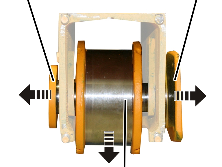
Bearing bolt |
Bearing flange |
|
| |
|
Wheel | |
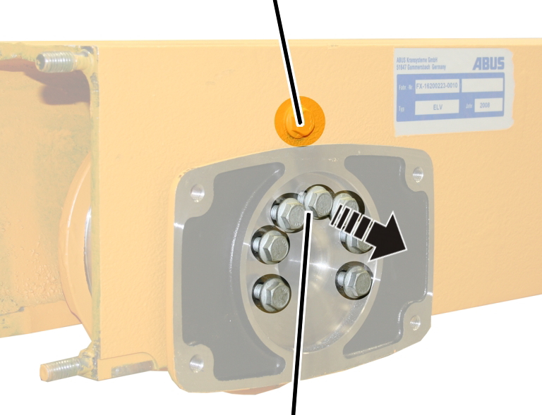
Take out the bearing bolt,
bearing flange and wheel.
Note:
Only for size 420 with crane travel drive 420 V: An adapter is also inserted on the bearing flange. If this cannot be easily taken off, it can remain on the bearing flange when the wheel is removed.
Tip:
To be able to easily remove the bearing flange from the end carriage, screw two or four screws in the corners of the bearing flange and thereby press the bearing flange off the end carriage.
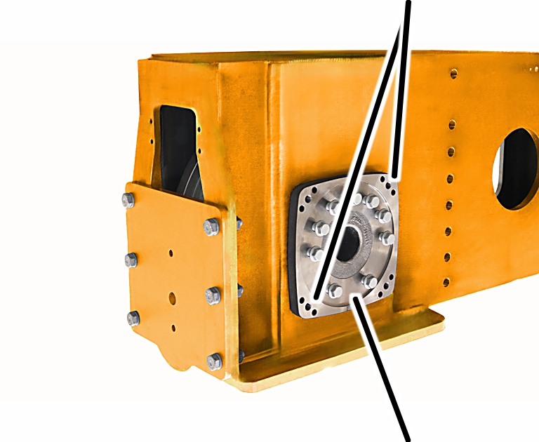
This work step applies only to end carriages of size 500.
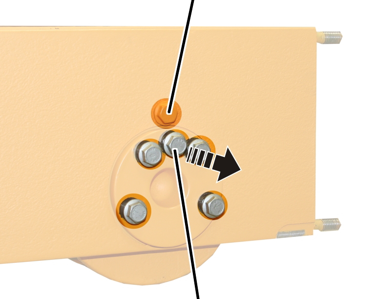
Tip:
|
|
Threaded holes |
|
| |
|
|
Bearing bolt |
To be able to remove the bearing bolts more easily, insert two screws into free threaded holes on the bearing bolt, opposite each other. This makes it easy to push the bearing bolt out of the end carriage.